1
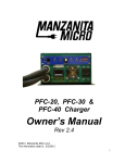
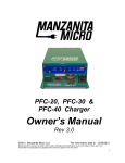
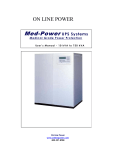
H2Optimal, Inc. www.pitlessunit.com VST2115P OPTIMAL DRIVE USER’S MANUAL Ver 1.2 2 Dear Customer Thank you for selecting the VST2115P Optimal Drive. This user’s manual explains how to use your VST2115P Optimal Drive. So please read this manual before installing and operating your VST2115P. Keep this manual for your future reference. H2OPTIMAL, INC. 1283 County Road H Ithaca, NE 68033 402 450-8461 Fax: 402 623-4247 www.pitlessunit.com [email protected] H2Optimal, Inc. VST2115P User’s Manual 3 Revision history: Date Version May, 2010 1.0 Modifications N/A Default parameter value of P.05 is changed from 1 sec to 0.5 sec Aug, 2012 1.1 The common and auxiliary windings are interchanged for 1ph, 3 wire motor Nov, 2013 1.2 Modifications are done in the parameter list and drive operation H2Optimal, Inc. VST2115P User’s Manual 4 Contents Page Disclaimer 5 Safety Information 6 1. System Description 7 1.1. Introduction 1.2. Display 1.3. Key Description 7 7 7 2. Installation 8 2.1. Introduction 2.2. Mounting the Drive 2.3. Wiring Diagram 2.4. Terminal Description 8 8 10 12 3. Programming the Drive 13 3.1. Introduction 3.2. Setting Parameters 13 13 4. Drive Operation 17 4.1. Introduction 4.2. Basic Operation 4.3. Troubleshooting 4.4. Fault Displays 17 17 18 19 5. Drive Maintenance 20 5.1. Introduction 5.2. Maintenance 20 20 VST2115P Technical Details 21 Environmental Specifications Drive Specifications H2Optimal, Inc. 21 22 VST2115P User’s Manual 5 Disclaimer H2OPTIMAL, INC. shall not be liable for any incidental or consequential damages, loss of revenues resulting from the use or misuse of information contained. H2OPTIMAL, INC. reserves the right to make changes in the design or material of the system without incurring any obligation to incorporate such changes in the product or part already in usage. H2Optimal, Inc. VST2115P User’s Manual 6 ! SAFETY INFORMATION Before installing and putting the VST2115P into operation, please read these safety instructions carefully. The drive contains hazardous voltages that are fatal for the user. Hence installation and maintenance must be performed by qualified technicians only. Power to the drive must be switched OFF before making/changing any connections. The DC-link capacitor remains charged to dangerous voltages even when the power is removed. For this reason it is not permissible to open the cover until 15 minutes after the display goes OFF. Even when the motor is stopped dangerous voltages are present at L1, L2 and B, Y, R terminals. Do not install the drive near sources producing noise such as solenoid, contactor, relay etc., Install noise suppressors in noise producing components located near the drive. Confirm that input supply voltage and frequency match the specified VST2115P input voltage and frequency before connecting. Make sure that the terminals to which mains supply, motor and control cables are connected are tightened properly. Do not touch the heat sink to avoid burns due to high temperature. Provide sufficient ventilation on all sides of the drive. There are no user serviceable parts in the VST2115P. In case of failure send the unit to factory for repair. ! DANGER Failure to follow these instructions can result in death or serious injury to the personnel or equipment damage H2Optimal, Inc. VST2115P User’s Manual 7 1. System Description 1.1. Introduction VST2115P is exclusively designed to drive up to a maximum 1hp single phase induction motor or up to a maximum 1 ½ hp three phase induction motor in pump applications with the input voltage of 220 to 240 Vac 1Ф, 50/60 Hz. 1.2. Display The display has four digits and is used to display the parameter number, values and fault codes. 1.3. Key description The required parameters can be entered using the three keys (<>, <>, < >). The parameter number and values are displayed on the four digit LED display. <> - Used to decrement the parameter number and values. <> - Used to increment the parameter number and values. < > - Used to set the parameter. H2Optimal, Inc. VST2115P User’s Manual 8 2. Installation 2.1. Introduction This chapter describes how to install the unit both mechanically and electrically. 2.2. Mounting the Drive Before mounting the drive check for the environmental conditions as mentioned in Table A of technical details [Page #22]. Dimensions: Mounting dimension: All dimensions are in mm Figure 1 Overall dimension (W x H x D): 238 (9.5”) x 165 (6 5/8”) x 162 mm (6 ½”) Bolt Hole Mounting Pattern (W x H) 224 (9”) x 152 (6”) H2Optimal, Inc. VST2115P User’s Manual 9 Mounting Guidelines 1. 2. 3. 4. 5. 6. 7. 8. Remove the wall mounting brackets from the heat sink Invert the brackets and reinstall the mounting screws. Mount the unit vertically. Remove the top cover. Install proper strain relief connectors Feed the wires into the respective holes. Make the connections as per the wiring diagram [Refer Figure 2(a) 2(b), 2(c)]. Refix the top cover. Mounting Recommendations 1. 2. 3. 4. 5. 6. 7. Install the unit vertically at ± 10º. Do not install the unit near sources producing noise solenoid, contactor, relay etc., Provide sufficient ventilation on all sides of the unit. Free space in front of unit: 10mm minimum. The control cable (Pressure sensor input) must be kept from the motor and mains cables. All wires/cables entering and exiting the drive should be firmly so that no load is applied to the wire connections connectors. Follow all requirements of NEC or CSA as appropriate. such as separate attached from the Motor Rating Before connecting the motor check for rating of the motor. Motor Single phase Three phase Design limit 1 hp 1.5 hp Table 1 The selection in parameter P.01 and actual motor connected must be the same. H2Optimal, Inc. VST2115P User’s Manual 10 2.3. Wiring Diagram Make the connections as per the wiring diagram shown in Figure 2(a) for 1Φ, 2wire, maximum 1 hp motor Figure 2(b) for 1Φ, 3wire, maximum 1 hp motor Figure 2(c) for 3Φ, maximum 1.5 hp motor DI 18V COM L2 L1 . Mains earth . Motor body R Y B VST2115P CB-2P 20A, C-curv e 1 E L1 L2 1ph, 1 hp motor Pressure switch Input m ains 220 to 240Vac, 1Ph, 50/60Hz Figure 2 (a) Wiring diagram for 1Φ, 2wire, maximum 1 hp motor H2Optimal, Inc. VST2115P User’s Manual 11 Motor body DI 18V COM L2 L1 . Mains earth . R Y Aux. winding Common Main winding B VST2115P CB-2P 20A, C-curv e 1 E L1 L2 1ph, 1 hp motor Pressure switch Input m ains 220 to 240Vac, 1Ph, 50/60Hz Figure 2(b) Wiring diagram for 1Φ, 3wire, maximum 1 hp motor H2Optimal, Inc. VST2115P User’s Manual 12 DI 18V COM L2 L1 . . R R Mains earth Y Motor body B Y B VST2115P CB-2P 20A, C-curv e 3 E L1 L2 3ph, 1.5 hp motor Pressure switch Input m ains 220 to 240Vac, 1Ph, 50/60Hz Figure 2(c) Wiring diagram for 3Φ, maximum 1.5 hp motor 2.4. Terminal Description Terminal L1 L2 Description Power input Drive ground (Earth) B Y R 1Φ, 2wire Load 1 Load 2 Not used 1Φ, 3wire Main winding Common Start winding 3Φ B Y R Motor ground DI 18 V COM Digital input - Pressure sensor Pressure sensor power Common (18V) Not Used! Table 2 H2Optimal, Inc. VST2115P User’s Manual 13 3. Programming the Drive 3.1. Introduction This chapter describes how to program the drive parameters using 4 digit, seven segment LED display, and three tactile keys. 3.2. Setting Parameters The list of parameters is given in Table 3. Parameters (except P.00) are password protected to prevent accidental changes. Parameters can be accessed only in stop mode. To program the parameters: 1. Remove the top cover. Before removing the top cover ensure that the drive is powered OFF. 2. 3. Power on the drive. Deactivate the pressure sensor input. This can be done by removing the sensor wire from the drive or sensor or as described below. The pressure sensor input can be deactivated by pressing <> and <> keys together for 3 seconds when the pressure sensor input is activated. The display toggles between and parameter (P.00) selection till the pressure sensor input is activated. 4. Press <> key twice while in default display. The system requests a password as below. 5. Enter the password as ‘10’ using <> and <> keys and then press < > key. H2Optimal, Inc. VST2115P User’s Manual 14 6. Then scroll the parameter list using <> or <>until the desired parameter is reached. 7. Press < > to change the parameter value. 8. Press <> or <> to increase or decrease the parameter value respectively. 9. Then press < > to save the parameter. The display blinks twice. This is to indicate that it is being saved. 10. After programming the desired parameter(s), press <> or <> until the parameter P.00 is reached. 11. Then press <> key. The system displays the value (default display) depending upon the parameter P.00 selection. 12. Activate the pressure sensor input. The pressure sensor input can be activated by pressing <> and <> keys together for a second when the pressure sensor input is deactivated. The display flashes to indicate that the pressure sensor input is activated. To load default parameters: 1. 2. 3. 4. 5. Make sure that the pressure sensor input is deactivated. Go to parameter P.21 and press < > key. The system requests a password. Enter the password and press < > key. The current values of all the parameters will be lost as they will be overwritten by default parameters. (The display shows and blinks to indicate that the parameters are being loaded). Parameters can be accessed only in stop mode. Before operating the drive in the system ensure that the parameters are configured correctly. The display always shows the default value (P.00 selection) while the motor is running. ! CAUTION While in parameter value entry, the motor will not run even if the pressure is below the pressure sensor setpoint. H2Optimal, Inc. VST2115P User’s Manual 15 Parameter List Parameter P.00 Description Display selection Range Default 0 - Output frequency 1 - Motor RMS current 2 - AC input voltage 3 - DC bus voltage 4 - Offset value 5 - Vth bits 0 - 1 phase, 2 wire 1 - 3 phase motor 2 - 1 phase, 3 wire 0 Factory use P.01 Motor selection P.02 Control frequency 5 - 80Hz 60 P.03 Base frequency 50 - 60Hz 60 P.04 Start mode frequency 5 - 60 Hz 50 P.05 Start acceleration ramp 0.5 - 30.0 seconds 0.5 P.06 Control acceleration ramp 0.5 - 30.0 seconds 3.0 P.07 Control deceleration ramp 0.5 - 30.0 seconds 3.0 P.08 Minimum frequency 10 - 60 Hz 40 P.09 Stop acceleration ramp 0.5 - 120.0 seconds 2.0 P.10 Stop mode frequency 10 - 60 Hz 55 P.11 Stop mode time period 0.1 -60.0 seconds 2.0 P.12 Control method 0 - Linear V/F 1- Quadratic V/F P.13 Starting torque boost 0.0 - 25.0% 10.0 P.14 Motor thermal current 1.0 - 10.0A 5.9 P.15 Minimum time to start after motor stop 0.0 - 60.0 seconds 5.0 H2Optimal, Inc. 0 1 VST2115P User’s Manual 16 Parameter Description Range Default P.16 Dry run current 0.1-10.0 A P.17 Dry run check time 1-999 seconds 5 P.18 Dry run OFF time 1-999 minutes 5 P.19 1.0 Factory use P.20 Calibration 0-Not active 1- Do offset calibration P.21 Load default Default values are loaded after password authentication P.22 Pressure input validation time 5-999 milli seconds P.23 Voltage ratio ( for 1Φ, 3 wire only) 1.00 to 1.30 P.24 P.25 1 1.20 Factory use System check period 90 0-9999 seconds P.26 P.27 P.28 0 Factory use Constant to calculate stop mode frequency in control mode P.29 80-150% 100 Factory use P. 30 Pressure sensor check time before going to stop mode 0-999.9 seconds 6.0 P.31 Constant to calculate stop mode frequency for every system check period. 80-150% 105 P.32 Frequency command increment or decrement in control mode 0.1 -10.0 Hz 3.0 P.33 Pressure sensor close state check time 0-9999 milliseconds 50 P.34 Pressure sensor open state check time 0-9999 milliseconds 50 Table 3 H2Optimal, Inc. VST2115P User’s Manual 17 4. Drive operation 4.1. Introduction This chapter describes the operation of the drive and faults displayed by the drive. 4.2. Basic Operation Before operating the drive make sure that it is installed as per the instructions given in Chapter 2 and the parameters are programmed to the correct values. 1. 2. 3. 4. 5. 6. When the pressure sensor is in closed state and the drive is in standby mode, the drive output ramps up to the start mode frequency (P.04) with programmed start acceleration ramp (P.05). After reaching the start mode frequency (P.04), the drive enters the control mode. In control mode the drive output will ramp up or down depending on the state of pressure sensor: If the pressure sensor is in closed state, the drive output will ramp up till the control frequency (P.02) is reached or till the pressure sensor opens. (or) If the pressure sensor is in open state, then the drive output will ramp down until the minimum frequency (P.08) is reached or till the pressure sensor closes. If in control mode the drive output reaches the minimum frequency (P.08) and the pressure sensor remains open for pressure sensor check time (P.30), then the drive output will ramp up to stop mode frequency with stop acceleration ramp (P.09). The stop mode frequency is calculated as follows a) It is the product of the output frequency, noted when the pressure sensor opens in control mode, and a constant % (P. 28). (or) b) It is the product of the output frequency, noted at the end of every system check period (P.25), and a constant % (P.31). The stop mode frequency is maintained for stop mode time period (P.11) and after that the drive output is switched OFF and the drive reaches standby mode. During stop mode if the pressure sensor closes then the drive returns to control mode. H2Optimal, Inc. VST2115P User’s Manual 18 4.3. Troubleshooting Improper operation should be corrected by following the methods: 1. Motor is noisy or overload trips or drive trips of . 2. Check setting of P.01, set to match motor type. System over pressurizes during stop mode. Reduce P.09 and/or P.11 to reduce system shut off pressure. If desired to have addition pressure at shut-off, these parameters can be increased. 3. Nuisance tripping with display of . Adjust P.16 to 75-80% of FLA from the motor name plate. P.16 is automated to determine the correct value to trip at dry run conditions. However, certain installations may experience nuisance tripping. Setting P.16 will eliminate nuisance tripping. If you know the well may experience low water levels, check the automated operation of P.16 during installation. After initial startup cycle, run the system for a minimum of three times and then check to see if the dry run feature works correctly. P.16 can be set at 75-80% of FLA of the motor to insure motor protection. 4. Radio interference or other noise problems. Check drive installation for proper grounding. Filters are available for installations where drive noise causes problems. 5. indicates there is a short or ground in the wiring or the motor. The drive is protecting itself when this fault occurs. Check wiring and motor with a megohm meter and correct the problem. Note: Some motors will appear to operate properly with a short to ground. Any system with grounds or shorts will not operate when using a drive. 6. Nuisance tripping. Check all wiring connections and all grounding. 7. Other faults are shown in Section 4.4. H2Optimal, Inc. VST2115P User’s Manual 19 8. 4.4. Fault Displays In case of fault, the drive indicates the fault by displaying the fault code. Fault code Fault Module fault Over voltage Under voltage (Only for 3 Φ motors) Overload fault Dry run fault Earth fault Cause This is triggered on power module control supply under-voltage or power module over current. This is triggered when the DC bus voltage exceeds 390Vdc. This is triggered when the input voltage goes below 150Vac. This is triggered when the motor current exceeds P.14 of Table 3 for a certain time period. (or) when the motor current exceeds 150% of the parameter P.14 This is triggered when the motor current drops below P.16 for the time period (P.17) of Table 3 This is triggered when the earth leakage occurs. Table 4 In case of any fault, the drive output is switched OFF until the fault is cleared. The drive output is switched on after the time period (P.15) has elapsed. If there is no fault present and pressure sensor input is in closed state. ! CAUTION The drive will protect only 3 phase motor from overload. Equipment does not incorporate motor overload protection for 1 phase motor. H2Optimal, Inc. VST2115P User’s Manual 20 ! CAUTION Drive will only trip when the current reaches or exceeds 106% of set current (for 1.5hp, 3 phase motor load) ! CAUTION Once the fault is cleared, the motor will start running after the time period (P.15) if the pressure switch input is closed. 5. Drive Maintenance 5.1. Introduction This chapter describes how to maintain the drive. 5.2. Maintenance If a problem arises during installation or operation of the drive, a) Make sure the drive is installed as per the instructions given in Chapter 2 and the parameters are programmed to the correct values. b) Check for the environmental conditions as mentioned in Table A of technical details [Page 22]. The following operations are to be carried out at regular intervals with the drive in powered off condition. a) Check the condition and tightness of connectors. b) Check the environmental conditions. c) Keep the surroundings of the drive clean. ! DANGER Before proceeding with any maintenance work, switch off the drive and wait 15 minutes after the display goes off. Safety information must be carefully read and followed. Otherwise death or serious injury to the personnel or equipment damage may occur. H2Optimal, Inc. VST2115P User’s Manual 21 VST2115P Technical Details Table A. Environmental Specifications S.no Parameter Range / Requirements 1 Vibration 2 Shock 3 Electro Magnetic radiation 4 Atmospheric pollution 5 Relative humidity 90% non-condensing max 6 Ambient temperature 7 Water 8 Overheating 0 to 40 Do not install the unit in a place where condensation will occur Make sure that there is an adequate air-flow for cooling 9 Operating position H2Optimal, Inc. Unit Do not install the inverter in an area that are subject to vibration Do not drop the inverter or expose it to sudden shock Do not install the unit near sources producing noise such as solenoid, contactor, relay etc., Do not install the inverter in a polluted environment which contains dust, corrosive gases, etc., Vertical VST2115P User’s Manual ºC 22 Table B. Drive Specifications S.no Parameter 1 Control method 2 3 4 Control frequency Input voltage (rms) Input frequency 5 Motor connections 6 7 8 9 10 11 12 13 Maximum continuous output current (rms) Input current (rms) Motor voltage (rms) Overload (over torque) Maximum lead cross section Earth wire cross section Input and output connectors tightening torque Recommended CB rating 14 Drive protection 15 Pump protection 16 Digital input 17 18 Display Keypad H2Optimal, Inc. Range / Characteristics Quadratic V/F with customized software for pressure control based on pressure sensor input 5 to 80 220 to 240, 1phase 50/60 2 output terminals (B,Y): 2 leads for single-phase motors with inaccessible start winding 3 output terminals (B,Y,R): 3 leads for 3 wire single phase motors 3 leads for three-phase motors 9.8 (For 1Φ, 1hp) 6.1 (For 3 Φ, 1.5hp) 12.2 230 110% for 60 seconds Input Output AWG#10 AWG#10 AWG#10 Unit 1.35 Nm Hz V Hz A A V % AWG AWG 20A, 2P, C-curve Over voltage protection Under voltage protection Short circuit protection Over temperature protection Earth fault protection Over load protection (3 Φ motor only) Dry run detection 10V-30Vdc opto-isolated input suitable for connection to a potential free contact 4 digit 7-segment LED display 3 key tact-switch keypad VST2115P User’s Manual 23 S.no 19 20 21 22 23 24 25 Parameter Adjustable parameters (password protected) Operating position Ambient temperature Humidity Dimensions (W x H x D) Weight Enclosure H2Optimal, Inc. Range / Characteristics a) 1-phase / 3-phase motor b) Start acceleration ramp c) Start mode frequency d) Control frequency e) Control acceleration ramp f) Control deceleration ramp g) Stop mode threshold frequency h) Stop mode stop frequency i) Stop mode time period j) Motor thermal current Vertical 0 to 40 90% non condensing max. 238 x 165 x 162 4.07 NEMA 1 Unit Seconds Hz Hz Seconds Seconds Hz Hz Seconds A C Mm Kg VST2115P User’s Manual 24 Please feel free to contact us if any technical assistance is required. H2OPTIMAL, INC. 1283 County Road H Ithaca, NE 68033 402 450-8461 Fax: 402 623-4247 www.pitlessunit.com [email protected] H2Optimal, Inc. VST2115P User’s Manual