1
EI-500 User Manual
EI-500 Series
220V Class 1HP~7½ HP
440V Class 1HP~10 HP
Read this manual carefully before installing, wiring,
operating, servicing or inspecting the drive.
Keep this manual within easy reach for quick reference.
RICH ELECTRIC CO., LTD.
Thank you for purchasing ERIC-500 Variable Speed Drives!
SAFETY INSTRUCTIONS
Always follow safety instructions to prevent accidents and potential hazards from occurring.
In this manual, safety messages are classified as follows:
WARNING Improper operation may result in serious personal injury or death.
operation may result in slight to medium personal injury
CAUTION Improper
or property damage.
Throughout this manual we use the following two illustrations to make you aware of safety
considerations:
Identifies potential hazards under certain conditions.
Read the message and follow the instructions carefully.
Identifies shock hazards under certain conditions.
Particular attention should be directed because dangerous voltage may be present.
Keep operating instructions handy for quick reference.
Read this manual carefully to maximize the performance of EI-500 series inverter and ensure its
safe use.
WARNING
Do not remove the cover while power is applied or the unit is in operation.
Otherwise, electric shock could occur.
Do not run the inverter with the front cover removed.
Otherwise, you may get an electric shock due to high voltage terminals or charged capacitor
exposure.
Do not remove the cover except for periodic inspections or wiring, even if the input power is
not applied.
Otherwise, you may access the charged circuits and get an electric shock.
Wiring and periodic inspections should be performed at least 10 minutes after disconnecting
the input power and after checking the DC link voltage is discharged with a meter (below
DC 30V).
Otherwise, you may get an electric shock.
I
Operate the switches with dry hands.
Otherwise, you may get an electric shock.
Do not use the cable when its insulating tube is damaged.
Otherwise, you may get an electric shock.
Do not subject the cables to scratches, excessive stress, heavy loads or pinching.
Otherwise, you may get an electric shock.
CAUTION
Install the inverter on a non-flammable surface. Do not place flammable material nearby.
Otherwise, fire could occur.
Disconnect the input power if the inverter gets damaged.
Otherwise, it could result in a secondary accident and fire.
After the input power is applied or removed, the inverter will remain hot for a couple of
minutes.
Otherwise, you may get bodily injuries such as skin-burn or damage.
Do not apply power to a damaged inverter or to an inverter with parts missing even if the
installation is complete.
Otherwise, electric shock could occur.
Do not allow lint, paper, wood chips, dust, metallic chips or other foreign matter into the
drive.
Otherwise, fire or accident could occur.
OPERATING PRECAUTIONS
(1) Handling and installation
Handle according to the weight of the product.
Do not stack the inverter boxes higher than the number recommended.
Install according to instructions specified in this manual.
Do not open the cover during delivery.
Do not place heavy items on the inverter.
Check the inverter mounting orientation is correct.
II
Do not drop the inverter, or subject it to impact.
Use the Type 3 grounding method for 220 V Class and special Type 3 for 440V class.
(Ground impedance: Below 100 ohm).
Take protective measures against ESD (Electrostatic Discharge) before touching the pcb for
inspection or installation.
Environment
Use the inverter under the following environmental conditions:
Ambient temperature
Relative humidity
Storage temperature
Location
Altitude, Vibration
Atmospheric pressure
-10 ℃ ~ +50 ℃ (non-freezing)
90% RH or less (non-condensing)
-20 ~ +60 ℃
Protected from corrosive gas, combustible gas, oil mist or
dust
Max. 1,000m above sea level, Max. 5.9m/sec2 (0.6G) or less
70 ~ 106 kPa
(2) Wiring
Do not connect a power factor correction capacitor, surge suppressor, or RFI filter to the
output of the inverter.
The connection orientation of the output cables U/T1, V/T2, W/T3 to the motor will affect
the direction of rotation of the motor.
Incorrect terminal wiring could result in the equipment damage.
Reversing the polarity (+/-) of the terminals could damage the inverter.
Only authorized personnel familiar with ERIC inverter should perform wiring and
inspections.
Always install the inverter before wiring. Otherwise, you may get an electric shock or have
bodily injury.
(3) Trial run
Check all parameters during operation. Changing parameter values might be required
depending on the load.
Always apply permissible range of voltage to the each terminal as indicated in this manual.
Otherwise, it could lead to inverter damage.
III
(4) Operation precautions
When the Auto restart function is selected, stay away from the equipment as a motor will
restart suddenly after an alarm stop.
The “STOP” key on the keypad is valid only when the appropriate function setting has been
made. Prepare an emergency stop switch separately.
If an alarm reset is made with the reference signal present, a sudden start will occur. Check
that the reference signal is turned off in advance. Otherwise an accident could occur.
Do not modify or alter anything inside the inverter.
Motor might not be protected by electronic thermal function of inverter.
Do not use a magnetic contactor on the inverter input for frequent starting/stopping of the
inverter.
Use a noise filter to reduce the effect of electromagnetic interference. Otherwise nearby
electronic equipment may be affected.
In case of input voltage unbalance, install AC reactor. Power Factor capacitors and
generators may become overheated and damaged due to potential high frequency noise
transmitted from inverter.
Use an insulation-rectified motor or take measures to suppress the micro surge voltage
when driving 440V class motor with inverter. A micro surge voltage attributable to wiring
constant is generated at motor terminals, and may deteriorate insulation and damage motor.
Before operating unit and prior to user programming, reset user parameters to default
settings.
Inverter can easily be set to high-speed operations, Verify capability of motor or machinery
prior to operating unit.
Stopping torque is not produced when using the DC-Break function. Install separate
equipment when stopping torque is needed.
(5) Fault prevention precautions
Provide a safety backup such as an emergency brake which will prevent the machine and
equipment from hazardous conditions if the inverter fails.
(6) Maintenance, inspection and parts replacement
Do not conduct a megger (insulation resistance) test on the control circuit of the inverter.
Refer to Chapter 6 for periodic inspection (parts replacement).
IV
(7) Disposal
Handle the inverter as an industrial waste when disposing of it.
(8) General instructions
Many of the diagrams and drawings in this instruction manual show the inverter without a
circuit breaker, a cover or partially open. Never run the inverter like this. Always place the
cover with circuit breakers and follow this instruction manual when operating the inverter.
V
CONTENTS
CHAPTER 1 INSTALLATION………………………………….…………………………………….. 3
■ Inspection…………………………………………………………………………………………. 3
■ Environmental Conditions………………………………………………………………………... 3
■ Mounting………………………………………………………………………………………….. 3
■ Other Precautions……………………………………………………………………………….… 4
■ Dimensions………………………………………………………………………………………... 5
■ Standard Wiring…………………………………………………………………………………... 8
■ Terminal Description……………………………………………………………………………... 9
■ Wiring Power Terminals………………………………………………………………………….. 10
■ Wires and Terminal Specification………………………………………………………………… 12
■ Control Terminals………………………………………………………………………………… 13
■ Control Terminals Wiring………………………………………………………………………… 14
CHAPTER 2 TEST RUN……………………………………….………………………………………. 15
■ Digital Operator (RCU-500) Operation…….…………………………………………………….. 15
■ Constant Setting and Change……………………………………………………………………... 16
■ Constant Group…………………………………………………………………………………… 19
■ Test Run…………………………………………………………………………………………... 21
CHAPTER 3 CONSTANTS LIST…………………………….……………………………………….. 22
■ Function Group U (Drive Group)…………..…………………………………………………….. 22
■ Function Group A (Standard Group)……………………………………………………………... 23
■ Function Group b (Application Group)………….……………………………………………….. 25
■ Function Group C (Multi-function Terminal Constant Group)…………………………………... 28
CHAPTER 4 CONSTANT…………………………………….………………………………………... 31
■ Function Group U (Drive Group)…………..…………………………………………………….. 31
■ Function Group A (Standard Group)……………………………………………………………... 39
■ Function Group b (Application Group)………….……………………………………………….. 56
■ Function Group C (Multi-function Terminal Constant Group)…………………………………... 72
CHAPTER 5 TROUBLESHOOTING AND MAINTENANCE……………………………………... 92
■ Fault Display………………………………..…………………………………………………….. 92
■ Fault Remedy……………….………..………………………………………………………….... 95
■ Troubleshooting…..………………………………………………………………………………. 97
■ Check Power Components (IGBT)……………………………………………………………….. 98
VI
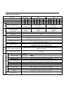
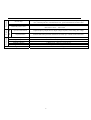
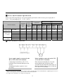
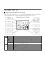
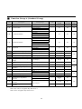
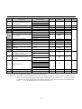
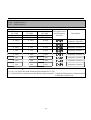
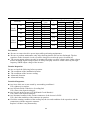
Standard Specification
Voltage Class
Model EI-500Max. Application Motor Output (HP)
Output
Features
Max. Application Motor Output (KW)
Rated Output Current (A)
Max. Output Voltage (V)
220VClass
Single-phase
S1L
S2L
S3L
1
2
3
0.75
1.5
2.2
5
8
12
3-phase 200~230V
(Proportional to input
voltage)
01L
1
0.75
5
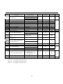
Control Features
Power
Supply
Max. Output Frequency (Hz)
Rated Input Voltage
and Frequency
Allowable Voltage Fluctuation
Allowable Frequency
Fluctuation
Control Method
Frequency Setting Resolution
Frequency Accuracy
V/F Ratio
Overload Capacity
Dynamic
Braking
Torque Boost
07L
7.5
440V Class
3-phase
01H 02H 03H 05H 07H 10H
1
2
3
5
7.5 10
1.5
2.2
3.7
5.5 0.75
8
12
16
25
2.5
3-phase 200~230V
(Proportional to
input voltage)
400Hz (Programmable)
3-phase
200~230V
50/60Hz
-15+10%
1.5 2.2 3.7 5.5
4
6
8
15
3-phase 380~460V
(Proportional to
input voltage)
±5%
V/F Control (SVPWM)
Digital reference: 0.01Hz (less than 100Hz), 0.1 Hz (100Hz or more)
Analog reference: 0.03Hz/ 50Hz
Digital reference: 0.015 of Max. Output Frequency.
Analog reference: 0.1% of Max. Output Frequency.
Linear, Square Pattern, User V/F
150% rated output current for one minute.
(Characteristic is inversely proportional to time)
Manual torque boost (0~15%);Auto torque boost
Continuous regenerative torque:Approx.:20% (150% with optional braking resistor,
braking resistor built-in)
Max. Continuous Braking Time
15 seconds
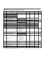
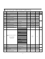
Output
Signal
Input Signal
Frequency Setting
Start Signal
Multi-step Speed
Multi-step
Accel/ Decel Time
Emergency Stop
S5
Fault Reset
Operation Status
Fault Output
Indicator
Operation Function
7.5
18
3-phase
380~460V
50/60Hz
Average Braking Torque
Operation Method
Operation Features
Single-phase
200~230V
50/60Hz
220V Class
3-phase
02L 03L 05L
2
3
5
key of digital operation/ External terminal S1, S2/ Communication Port
key of RCU-500/ Communication Port
0~10V/ 4~20mA (External terminal)/ Potentiometer of digital operator
Forward/ Reverse
Up to 8 speed can be set (Use Multi-function terminal)
0 ~ 999.9 sec, Up to 8 types can be set and selected for each setting (Use Multi-function terminal)
Accel/ Decel Pattern: Linear Pattern, U Pattern, S Pattern
Interrupts the output of Inverter
Jog Operation
Reset faults when protective function is active.
Frequency level detection, overload alarm, over current, over voltage, under voltage, inverter
overheat, running, stop, constant speed, speed searching
Contact output (MA, MC, MB) – AC250V 1A/ DC 30V 1A
Output frequency, output current, output voltage, DC voltage indicator selection
(Output pulse:500Hz, Output Voltage:0~10V)
DC braking, frequency limit, frequency jump, second function, slip compensation, reverse
rotation prevention, auto restart, PID control
Digital reference:
Analog reference:
1
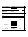
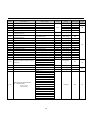
Environment
Inverter Alarm
Momentary Power Loss
RCU-500
Display
Protection
Inverter Trip
Over voltage, under voltage, over current, inverter overheat, motor overheat, input/ output phase
loss, overload protection, communication error, speed command loss, hardware fault
Stall prevention, overload alarm
Less than 15 msec.: Continuous operation
More than 15 msec.: Auto restart
Operation Information
Output frequency, output current, output voltage, frequency value setting, DC voltage
Trip Information
Indicates fault when protection function is activated, up to 5 faults can be memorized.
Ambient Temperature
Storage Temperature
Humidity
Altitude/ Vibration
Application Site
Cooling Method
-10℃~50℃ (Atmospheric Pressure:70-106kPa)
-20℃~60℃
Less than 90% RH Max.
1,000M or less, 5.9m/ sec² (=0.6g) or less
No corrosive gas, combustible gas, oil mist, or dust
Forced Air Cooling
2
CHAPTER 1
INSTALLATION
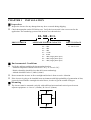
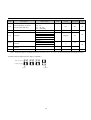
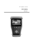
█ Inspection
Inspect the inverter for any damage that may have occurred during shipping.
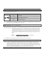
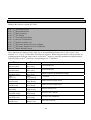
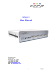
Check the nameplate on the EI-500 inverter. Verify the inverter unit is the correct one for the
application. The numbering system of the inverter is as shown below.
EI- 500 - 01 L
ERIC INVERTER
APPLICABLE MOTOR CAPACITY
01: 1 HP
02: 2 HP
03: 3 HP
05: 5 HP
07: 7.5 HP
10: 10 HP
S1: 1 HP (single-phase input )
S2: 2 HP (single-phase input)
S3: 3 HP (single-phase input)
INPUT VOLTAGE
L:220 V Class
H:440 V Class
█ Environmental Conditions
Verify the ambient condition for the mounting location.
- Ambient temperature should not be below -10℃ or exceed +50℃.
- Relative humidity should be less than 90% (non-condensing).
- Altitude should be below 3,300ft (1,000m).
Do not mount the inverter in direct sunlight and isolate it from excessive vibration.
If the inverter is going to be installed in an environment with high probability of penetration of dust,
it must be located inside watertight electrical boxes, in order to get the suitable IP degree.
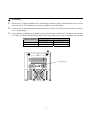
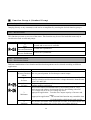
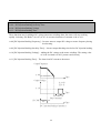
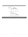
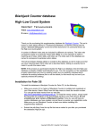
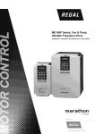
█ Mounting
The inverter must be mounted vertically with sufficient horizontal and vertical space between
adjacent equipment. A= Over 6" (150mm), B= Over 2"(50mm).
A
B
B
A
3
█ Other Precautions
Do not carry the inverter by the front cover.
Do not install the inverter in a location where excessive vibration is present. Be cautious when
installing on presses or moving equipment.
The life span of the inverter is greatly affected by the ambient temperature. Install in a location where
temperature are within permissible limits (- 10℃ ~ + 50 ℃).
The inverter operates at high-temperatures - install on a non-combustible surface.
Do not install the inverter in high-temperature or high-humidity locations.
Do not install the inverter in a location where oil mist, combustible gas, or dust is present. Install the
inverter in a clean location or in an enclosed panel, free of foreign substance.
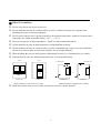
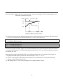
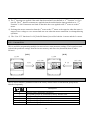
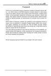
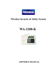
When installing the inverter inside a panel with multiple inverters or a ventilation fan, use caution.
If installed incorrectly, the ambient temperature may exceed specified limits.
Panel
Panel
Ventilating fan
Ventilating fan
Inverter
Inverter
Inverter
Inverter
Cooling fan
GOOD (O)
BAD (X)
GOOD (O)
[When installing several inverters in a panel]
BAD (X)
[When installing a ventilating fan in a panel]
Install the inverter using screws or bolts to insure the inverter is firmly fastened.
4
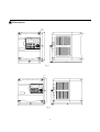
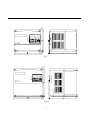
█ Dimensions
4-M4
ERICDRIVE R
SET
ALARM
FOR
REV
RUN
STOP
DIGITAL OPERATOR
RCU-500
Fig.1
4-M4
ERICDRIVE R
SET
ALARM
FOR
REV
RUN
STOP
DIGITAL OPERATOR
RCU-500
Fig.2
5
4-M4
ERICDRIVE R
SET
ALARM
FOR
REV
RUN
STOP
DIGITAL OPERATOR
RCU-500
Fig.3
4-M4
ERICDRIVE R
SET
ALARM
FOR
REV
RUN
STOP
DIGITAL OPERATOR
RCU-500
Fig.4
6
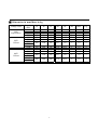
█ Dimension in mm/Mass in kg
Voltage Class
220V
Signal-Phase
220V
3-Phase
440V
3-Phase
Capacity
(HP)
1HP
2HP
3HP
1HP
2HP
3HP
5HP
7.5HP
1HP
2HP
3HP
5HP
7.5HP
10HP
W
H
D
W1
H1
H2
Mass
Fig.
98
129
150
98
129
130
130
130
130
130
131
153
155
131
153
88
117
137
88
117
117
118
117
117
118
7
6
7
7
6
0.9
1.5
1.8
0.9
1.5
1
2
3
1
2
150
130
155
137
117
7
1.8
3
190
98
129
200
130
130
186
131
153
176
88
117
185.5
117
118
5
7
6
3.8
0.9
1.5
4
1
2
150
130
155
137
117
7
1.8
3
190
200
186
176
185.5
5
3.8
4
7
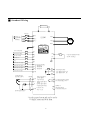
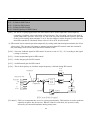
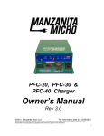
█ Standard Wiring
DB Resistor
P
PR
MCCB
1
3
R/L1
220V or
220/440V
50/60Hz
S/L2
U/T1
EI-500
RCU-500
G
MOTOR
V/T2
T/L3
ERICDRIVE
W/T3
R
SET
ALARM
FOR
REV
RUN
STOP
DIGITAL OPERATOR
RCU-500
Forward Run/Stop
S1
Reverse Run/Stop
FM
S2
Inverter Disable
S3
Fault Reset
FC
Output Frequency Meter
(0-10V Analog)
S4
Jog
S5
Multi-function Input 1
S6
Multi-function Input 2
S7
Multi-function Input 3
S8
Common Terminal
Factory Setting:
' SPEED-L '
' SPEED-M '
' SPEED-H '
MA
MC
COM
MB
Potentiometer
(1k Ohm,1/2W)
FM
Shield
Power supply for
speed signal:
+12V
+12V/ 10mA
Vs Speed signal input:
0-10V
Is Speed signal input:
4-20mA(250 Ohm)
Common for
COM
+12V,Vs,Is
Fault output relay
Less than AC250V, 1A
Less than DC30V, 1A
M1
M2
S+
S-
Less than DC24V/ 50mA
Factory setting: ' RUN '
RS485 &
MODBUS-RTU
Communication port
Speed signal input*
* Analog speed command can be set by
Voltage,Current and both them.
8
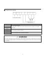
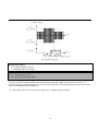
█ Terminal Description
R/L1
S/L2
T/L3
P
PR
U/T1 V/T2
W/T3
3-P hase P ow er Input
M otor
D B R esistor
Symbols
R/ L1
S/ L2
T/ L3
U/ T1
V/ T2
W/ T3
P
PR
Functions
AC Line Input Terminals
3(1) phase, 200 ~ 230V AC for 220V Class Units and 380 ~ 460V AC for 440V
Class Units.
3 Phase Output Terminals to Motor
Dynamic Braking Resistor Connection Terminals
WARNING
Normal stray capacitance between the inverter chassis and the power devices inside the inverter and AC
line can provide a high impedance shock hazard. Do not apply power to the inverter if the inverter frame
is not grounded.
9
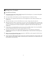
█ Wiring Power Terminals
◆
Precautions on Wiring
The internal circuits of the inverter will be damaged if the incoming power is connected and applied
to output terminals (U/ T1, V/ T2, W/ T3).
Use ring terminals with insulated caps when wiring the input power and motor wiring.
Do not leave wire fragments inside the inverter. Wire fragments can cause faults, breakdowns, and
malfunctions.
For input and output, use wires with sufficient size to ensure voltage drop of less than 2%.
When more than one motor is connected to one inverter, total wiring length should be less than 100m
(1,640ft). Do not use a 3-wire cable for long distances. Due to increased leakage capacitance between
wires, over-current protective feature may operate or equipment connected to the output side may
malfunction.
Connect only recommended braking resistor between the P and PR terminals. Never short P and PR
terminals. Shorting terminals may cause internal damage to inverter.
The main circuit of the inverter contains high frequency noise, and can hinder communication
equipment near the inverter. To reduce noise, install RFI filters or line noise filters on the input side
of the inverter.
Do not use power factor capacitor, surge suppressors, or RFI filters on the output side of the inverter.
Doing so may damage these components.
Always insure the LED and charge lamp for the power terminal are OFF before wiring terminals. The
charge capacitor may hold high-voltage even after the power is disconnected. Use caution to prevent
the possibility of personal injury.
10
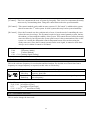
◆ Grounding
The inverter is a high switching device, and leakage current may flow. Ground the inverter to avoid
electrical shock. Use caution to prevent the possibility of personal injury.
Connect only to the dedicated ground terminal on the inverter. Do not use the enclosure or a chassis
screw for grounding.
As a minimum, grounding wire should meet the specifications listed below. Grounding wire should
be as short as possible and should be connected to the ground point as near as possible to the inverter.
Motor Capacity
1.0
7.5
~ 5.0 HP
~ 10 HP
Grounding Wire Sizes, AWG (mm²)
220V class
440V class
12 (3.5)
14 (2)
12 (3.5)
12 (3.5)
Ground Screw
11
█ Wires and Terminal Specification
Refer to the following table for wires and terminal specification of the inverter power input (R/L1、
S/L2、T/L3) and output (U/T1、V/T2、W/T3).
Inverter Capacity
220V Class
(Single-Phase)
220V Class
(3 - Phase)
440V Class
(3 - Phase)
Terminal
Screw
Size
Screw
Torque1
(Kgf·cm)/
lb-in
1 ~ 3 HP
M 4.0
15/ 10
1 HP
2 ~ 3 HP
5.0 HP
7½ HP
1.0 ~ 5.0 HP
7½ HP ~ 10HP
M 3.5
M 4.0
M 4.0
M 4.0
M 4.0
M 4.0
10/ 07
15/ 10
15/ 10
25/ 16
15/ 10
25/ 16
Wire2
Terminals
R/L1、
S/L2、
T/L3
U/T1、
V/T2、
W/T3
2 - 4
2 - 4
2
2
5.5
5.5
2
5.5
-
3.5
4
4
4
4
4
2
2
5.5
5.5
2
5.5
-
3.5
4
4
4
4
4
mm2
R/L1、 U/T1、
S/L2、 V/T2、
T/L3
W/T3
AWG
R/L1、 U/T1、
S/L2、 V/T2、
T/L3
W/T3
2
2
14
14
2
2
3.5
5.5
2
5.5
2
2
3.5
5.5
2
5.5
14
14
12
10
14
10
14
14
12
10
14
10
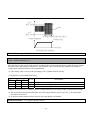
◆ Power and Motor Connection
R/L1 S/L2 T/L3
P
PR
U/T1 V/T2 W/T3
3-Phase Power Input
Motor
Power supply must be connected to the
R/L1, S/L2, and T/L3 Terminals.
Motor should be connected to the U/T1,
V/T2, and W/T3 Terminals.
Connecting it to the R/L1, S/L2, T/L3
terminals causes internal damages to the
inverter.
Arranging the phase sequence is not
necessary.
If the forward command (S1) is on, the
motor should rotate clockwise when
viewed from the load side of the motor. If
the motor rotates in the reverse, switch the
U/T1 and V/T2 Terminals.
1
Apply the rated torque to terminal screws. Loosen screws can cause short circuit and malfunction. Tightening the screws too
much can damage the terminals and cause short circuit and malfunction.
2
Use copper wires with 600V, 75℃ratings for wiring only.
12
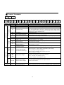
█ Control Terminals
1
MA
2
MC
1
2
COM S1
Starting Contact Function
Selection
3
S2
4
S3
Symbol
S1
S2
5
S4
6
S5
7
S6
8
S7
Name
Forward Run Command
Reverse Run Command
S3
Emergency Stop
S4
Fault Reset
S5
Jog Frequency Reference
S6, S7, S8
COM
+12V
Vs
Is
Description
Forward run when closed and stop when open.
Reverse run when closed and stop when open.
When the S3 signal is ON, output of Inverter is turned Off. When motor
uses an electrical brake to stop, S3 is used to turn Off the output signal.
When S3 signal is OFF (Not turned off by latching) and S1 Signal (or S2
Signal) is ON, motor continues to run.
Used for fault reset.
When Jog frequency is ON, operating at low frequency.
The direction is set by the S1 (or S2) Signal.
Used for multi-function input. Default is set to “Step Frequency 1, 2, 3”.
Common terminal for contact inputs.
Used as power for analog frequency setting.
Maximum output is +12V/ 100mA
Used for DC 0 ~ +10V input frequency reference.
Input resistance is 20 KΩ
Used for DC 4-20mA input frequency reference.
Input resistance is 250 Ω
Common Terminal for Analog Frequency Reference Signal
Output Selectable from one of following signal:
Output frequency, output voltage, output current, DC voltage.
Factory setting is “Output Frequency.”
Output voltage and output current are 0-12V/ 1mA.
Output frequency is 500Hz.
Activates when Protective Function is Operating.
AC250V/ 1A, DC30V/ 1A for Contact capacity
Fault:MA-MC close (MB-MC open),
Normal:MB-MC close (MA-MC open)
Analog
Output
Multi-function input 1, 2, 3
Sequence Common
Frequency Reference
Power (+12)
Frequency Reference Input
Signal (Voltage)
Frequency Reference Input
Signal (Current)
Frequency Reference
Common Terminal
20
S-
FM-FC
Relay
Contact
COM
9
10 11 12 13 14 15 16 17 18 19
S8 COM +12 Vs COM Is FM FC M1 M2 S+
MA
MC
MB
Transistor
Output Signal
Analog frequency
setting
Input Signal
Type
3
MB
M1-M2
Multi-function Output
(Open Collector Output)
Use After Defining Multi-function Output Terminal.
DC24V, 50mA or less.
S+, S-
MODBUS
Communication Port
RS485 Communication Port for protocol MODBUS-RTU Communication
RS-485
Analog/ Digital Output
(for External Monitoring)
Fault Contact Output
13
█ Control Terminals Wiring
◆ Precautions on Wiring
COM and M2 Terminal are mutually separated. Do not connect these two terminals to each other.
Meanwhile, do not connect COM and M2 Terminal to power source.
Use shielded wires or twisted wires for control circuit wiring, and separate these wires from the main
power circuits and other high voltage circuits. (Example:220V Relay sequence circuit.)
Use 1.25 mm² (22AWG) standard cable for control terminal wire.
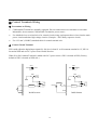
◆ Control Circuit Terminal
SW1 could adjust the digital input signal (S1~S8) level, when S1 to S8 common terminal is 0 V, SW1 is
located at NPN and use 24 V power source Inside Inverter.
When S1 to S8 Common Terminal is added with 24 V power source, SW1 is located at PNP. (Factory
default of SW1 is located at NPN side.)
SW1
PNP
SW1
NPN
PNP
SW1
NPN
SW1
24V
24V
COM
COM
S1
COM
DC24V
Resistor
S1
COM
Inside Inverter
14
Resistor
Inside Inverter
CHAPTER 2
█
TEST RUN
Digital Operator (RCU-500) Operation
EI-500 offers 4 types of function groups. It can be adjusted by Digital Operator (RCU-500) and input by
constant settings directly. The following is an illustration and functions of the RCU-500.
DISPLAY
(7-Segment)
UP Key
Digital Operator (RCU-500)
ERICDRIVE R
SET
ALARM
FOR
REV
RUN
STOP
INDICATOR
(1)SET
(2)ALARM
(3)FOR
(4)REV
(5)RUN
(6)STOP
DIGITAL OPERATOR
RCU-500
Class
Key
FUNC Key
RUN Key
ESC Key
Frequency setting
potentiometer
DOWN Key
STOP/RESET
Key
Display
FUNC
ESC
(Up)
(Down)
RUN
STOP/RESET
LED
SET
ALARM
FWD
REV
RUN
STOP
Description
Press to Change/ Adjust constant setting.
Exit key of function group U, A, b, C
Press to move through constants or to increase/ adjust constant values.
Press to move through constants or to decrease/ adjust constant values.
Use to operate inverter.
Press to stop inverter during operation.
Press to reset when a fault has occurred.
Lit when user is setting constants by using FUNC key
Lit when the inverter has fault trip.
Lit during forward run.
Lit during reverse run.
Lit when at constant speed and blinks when accelerating or decelerating.
Lit during the inverter has STOP the output status.
15
█
Constant Setting and Change
Numerous parameters are built into the inverter (EI-500). Basically, it can divided into 4 groups, there are:
(1) U Function Group (Drive Group)
(2) A Function Group (Basic Group)
(3) b Function Group (Application Group)
(4) C Function Group (Multi-function Terminal Group)
The digital operator RCU-500 allows to operate the inverter by setting the required parameters, and
adjusting, monitoring their value according to the load and operating conditions.
Function Group U ( U-01 ~ U-13) Operation Procedures
1. Move to the group code that needs changing by using
2. Press
3. Use
key.
key. The keypad LED (SET) will turn ON.
keys to set the parameter value.
4. Press
again upon the parameter value has been settled. The 7-segment display will blink
for 3 times. (i.e. the parameter values have been settled completely.) At the same time, the
keypad LED (SET) will turn OFF.
5. If the parameter value needs to get back to original value before pressing
key (The keypad LED (SET) will turn OFF).
, please press
A Function Group, b Function Group, C Function Group Operation Procedures
1. Use
2. Press
3. Use the
4. Press
5. Use
keys to move to desired Function Group.
key to enter the desired Function Group.
keys to set the parameter value to the desired code.
key (The keypad LED SET will turn ON.), and enter to the value of constant code.
keys to set and adjust the parameter value.
key again once the parameter value has been settled when the 7-segment display will
6. Press
blink for 3 times, the renew values has been stored in the inverter. Meanwhile, the keypad LED
(SET) will turn OFF.
7. To exit the Function Group, please press
key, then return to the Step 1.
If the parameter value can not be changed/ adjusted, determine if:
※ The value of constant attribute can’t be adjusted while inverter is running. (Refer to the function
table in Chapter 3.)
※ The Function might be locked in b-94 [Constants Write Protection]. (Refer to the constant
description in Chapter 4.)
16
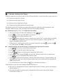
[Example] Change the deceleration time in U-02 from 60 sec to 40 sec.
Press
Press
SET
ALARM
SET
ALARM
FWD
REV
FWD
REV
FWD
REV
RUN
STOP
RUN
STOP
RUN
STOP
SET
ALARM
FWD
REV
RUN
STOP
FUNC
Press
SET
ALARM
FUNC
“ The 7-segment display will
blink for 3 times”
※ After the data setting is finished, press
key. The new data will blinks for 3 times when the data
setting is finished. It indicates data programming is completed.
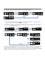
[Example] To Monitor Current Output in U-08 from the inverter while the inverter is running
(U-08 cannot be set)
SET
ALARM
FWD
REV
RUN
STOP
Press
FUNC
SET
ALARM
FWD
REV
RUN
STOP
Press
SET
FUNC
ALARM
FWD
REV
RUN
STOP
[Example] To Monitor Fault Type when a Fault Occurs in U-12
SET
ALARM
FWD
REV
RUN
STOP
FUNC
Press
SET
ALARM
SET
FWD
REV
FWD
ALARM
REV
RUN
STOP
RUN
STOP
(Output frequency is appear
when fault occurs.)
SET
ALARM
FWD
REV
RUN
STOP
(Output current is appear
when fault occurs.)
SET
Press
FUNC
ALARM
FWD
REV
RUN
STOP
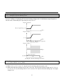
The fault type is auto-displayed in U-12 on operator when a fault occurs. Frequency, current and operating
status (accelerating, decelerating, in constant speeds) may be monitored by using the UP/DOWN key.
Example:Fault occurs when the inverter was accelerating at 40.28Hz, 20.5A, the keypad LED (ALRAM)
will blink. (The inverter must be turned OFF and turned ON again to remove the OC fault.)
17
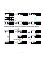
[Example] Adjusting Procedure for the parameter value of A Function Group when the inverter
stops. (A-05=1)
SET
ALARM
FWD
REV
RUN
STOP
Press
Press
FUNC
Press
SET
ALARM
FWD
REV
FWD
SET
ALARM
REV
RUN
STOP
RUN
STOP
SET
ALARM
FUNC
SET
ALARM
Press
Press
FWD
REV
ESC
FUNC
RUN
STOP
Press
(OR)
SET
ALARM
FWD
REV
RUN
STOP
Press
FUNC
SET
ALARM
FWD
REV
RUN
STOP
Press
FWD
REV
RUN
STOP
[Example] Setting Jump Code Procedure in A Function Code. Jump to code A-12 from A-00.
Jump Code Setting
SET
ALARM
FWD
REV
RUN
STOP
Press
FUNC
Press
FUNC
SET
ALARM
FWD
REV
RUN
STOP
SET
ALARM
FWD
REV
RUN
STOP
SET
Press
Press
SET
ALARM
REV
RUN
STOP
Press
FUNC
ALARM
FWD
REV
RUN
STOP
SET
ALARM
FWD
REV
RUN
STOP
SET
ALARM
FUNC
Jump to desired Code
FWD
FUNC
FUNC
SET
ALARM
FWD
REV
RUN
STOP
Press
FUNC
FWD
REV
RUN
STOP
(i.e.A-12=50)
18
█
Constant Group
The EI-500 series offers 4 Function Groups. The group’s names and the description are as bellow:
Group Name
Description
Function Group U (Drive Group)
Frequency Command, Accel/ Decel Time, etc.
Function Group A (Standard Group)
Max. Frequency, Torque Boost, etc.
Function Group b
(Application Group)
Frequency Jump, Frequency Limit, etc.
Function Group C
(Multi-function Terminal Group)
Multi-function terminal setting and sequence
operation constants
Refer to the parameter description in Chapter 4 for detailed description of each group.
19
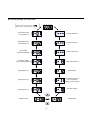
Moving through U Group Codes
〔
STOP:Reference Frequency (
RUNNING:Output Frquency
〕
)
Acceleration Time
(Acceleration 0)
C Group Selection
Deceleration Time
(Deceleration 0)
b Group Selection
Drive Mode
(Run/Stop Method)
A Group Selection
Frequency Mode
(Freq. Setting Method)
Motor Direction Set
Step Frequency 1
Fault Display
Step Frequency 2
User Display Selection
in b-73 (Output
voltage, Watt, Torque)
Step Frequency 3
DC link Voltage
Output Current
Motor Speed
20
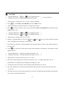
█
Test Run
Operation Reference:
key,
key of Digital Operator
〔 Frequency Reference:Potentiometer of Digital Operator
〕(Factory Default)
1. Turn the power ON and set U-03=0, U-04=1. (Factory Default)
2. Press
key. LED RUN and FOR (REV) will lit, STOP will lit.
3. Adjust potentiometer of digital operator to change motor speed.
4. Press
key for the motor to coast to stop. The LED of RUN and FOR (REV) will turn OFF and
STOP will turn ON.
〔
Operation Reference:
Frequency Reference:
key,
key,
key of Digital Operator
key of Digital Operator
〕
1. Turn the power ON and set U-03=0, U-04=0.
2. (Return 7-segment display to U-00.) Use
key,
key,
key to set the operation frequency
value. (It displays the set frequency value at stop.)
3. Press RUN key, the motor will start running. The output frequency is show on the digital operator at
the same time.
4. Press
key, the motor will decrease to stop. In the meantime, the frequency value appears on the
digital operator.
Reference:External Terminal (Terminal S1, S2)
〔 Operation
Frequency Reference:External Terminal (Terminal Vs or Is) 〕
1. Turn the power of motor ON and set U-03=1, U-04=2.
2. Have the external potentiometer connect to terminal +12V, Vs, COM to adjust the value of
potentiometer. The digital operator displays the frequency value.
3. To make the motor forward run, the terminal S1 and COM need to be closed.
4. Have the terminal S1 to be opened and terminal S2 and COM to be closed so that the motor does
reverse run.
5. The motor decreases to stop when terminal S2 is opened. The digital operator displays the frequency
value set by external potentiometer.
21
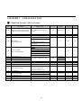
CHAPTER 3
█
Code
CONSTANTS LIST
Function Group U (Drive Group)
Description
Setting Range
U-00
Reference Frequency during stop
Output Frequency during running
0.00 to Max. output frequency
(A-20)
U-01
U-02
Acceleration Time
Deceleration Time
U-03
Drive Mode
(Run/Stop Method)
0.0 to 999.9 [sec]
0.0 to 999.9 [sec]
0 (Digital Operator)
1 External Terminal Pattern 1
(S1/S2-1)
2 External Terminal Pattern 2
(S1/S2-2)
3 (RS485)
U-04
Frequency Mode
(Freq. Setting Method)
U-05
U-06
U-07
U-08
U-09
U-10
Step Frequency 1
Step Frequency 2
Step Frequency 3
Output Current
Motor Speed
DC link Voltage
U-11
b-73 Selection Display
U-12
Fault Display
U-13
Motor Direction Set
A- - b- - C- - -
A Group Selection
b Group Selection
C Group Selection
0
key of RCU-500 (U-00)
1 Potentiometer of RCU-500
2 External Terminal (Vs)
3 External Terminal (Is)
4 External Terminal (Vs+Is)
5 (RS485) Communication Port
Units
Factory
Default
Adj.
During Run
Ref.
Page
0.01
00.00 [Hz]
Yes
31
0.1
0.1
10.0 [sec]
20.0 [sec]
Yes
Yes
31
31
-
0
No
32
-
1
No
33
Yes
35
-
36
36
36
0.00 to Max. Frequency(A-20)
0.01
0:Inverter Output Voltage
1:Inverter Output Watt
2:Inverter Output Torque
F (Forward)
r (Reverse)
[A]
[rpm]
[V]
10.00 [Hz]
20.00 [Hz]
30.00 [Hz]
-
-
-
-
37
-
0
-
37
-
F (Forward)
Yes
38
38
38
38
22
█
Function Group A (Standard Group)
Code
Description
A-00
Jump to Desired Code #
A-03
Run Prevention
A-05
Acceleration Pattern
A-06
Deceleration Pattern
A-07
Stop Mode
A-08
A-22
DC Injection Braking Frequency
DC Injection Braking ON-DELAY
Time
DC Injection Braking Voltage
DC Injection Braking Time
Starting DC Injection Braking
Voltage
Starting DC Injection Braking
Time
Maximum Output Frequency
Maximum Voltage Output
Frequency
Minimum Output Frequency
A-23
Frequency Limit Selection
A-24
A-25
Low Limit Frequency
High Limit Frequency
Manual/Auto Torque Boost
Selection
A-09
A-10
A-11
A-12
A-13
A-20
A-21
A-26
A-27
A-28
Setting Range
Units
Factory
Default
Adj.
During Run
Ref.
Page
1
3
Yes
39
-
0
No
39
-
0
No
39
-
0
No
39
41
1 to 99
0 (None)
1 (Forward Prev)
2 (Reverse Prev)
0 (Linear)
1 (S-Curve)
2 (U-Curve)
3 (Minimum)
4 (Optimum)
0 (Linear)
1 (S-Curve)
2 (U-Curve)
3 (Minimum)
4 (Optimum)
0 (Decel)
1 (DC-brake)
2 (Free-run)
A-22 to 50/60 [Hz]
-
0
No
0.01
5.00 [Hz]
No
0
to 60 [sec]
0.01
0.10 [sec]
No
0
0
to 200 [%]
to 60 [sec]
1
0.1
50 [%]
1.0 [sec]
No
No
0
to 200 [%]
1
50 [%]
No
0
to 60 [sec]
0.1
0.0 [sec]
No
40 to 400 [Hz]
0.01
50 / 60 [Hz]
No
30 to (A-20)
0.01
50 / 60 [Hz]
No
0.1 to 10 [Hz]
0 (No)
1 (Yes)
A-22 to A-25
A-24 to A-20
0 (Manual)
1 (Auto)
0.01
0.10 [Hz]
No
-
0
No
0.01
0.01
0.00 [Hz]
50 / 60 [Hz]
Manual
0
No
No
43
44
-
Manual - Torque Boost in Forward
Direction
0.0 to 15.0 [%]
Manual - Torque Boost in Reverse
Direction
※ Code A-08, A-09, A-11 appears only when A-07=1.
※ Code A-24, A-25 appears only when A-23=1.
23
45
45
No
0.1
2.0 [%]
No
0.1
2.0 [%]
No
46
Code
A-29
Volts/Hz Pattern
A-30
A-31
A-32
A-33
A-34
A-35
A-36
A-37
A-38
A-39
User V/F – Frequency 1
User V/F – Voltage 1
User V/F – Frequency 2
User V/F – Voltage 2
User V/F – Frequency 3
User V/F – Voltage 3
User V/F – Frequency 4
User V/F – Voltage 4
Maximum Output Voltage
Energy Save Level
A-50
Electronic Thermal Selection
A-51
A-52
Units
Factory
Default
Adj.
During Run
Ref.
Page
-
0
No
47
0.01
1
0.01
1
0.01
1
0.01
1
0.1
1
15.00 [Hz]
25 [%]
30.00 [Hz]
50 [%]
45.00 [Hz]
75 [%]
50 / 60 [Hz]
100 [%]
100.0 [%]
0 [%]
No
No
No
No
No
No
No
No
No
Yes
-
0
Yes
A-52 to 250 [%]
1
180 [%]
Yes
50 to A-51
1
120 [%]
Yes
-
0
Yes
1
0.1
150 [%]
10.0 [sec]
Yes
Yes
-
1
Yes
1
1
200 [%]
60.0 [sec]
Yes
Yes
bit
000
No
1
-
200 [%]
-
No
-
Description
Electronic Thermal Level for 1
Minute
Electronic Thermal Level for
Continuous
Setting Range
0 (Linear)
1 (Square)
2 (User V/F)
0.00 ~ A-32
0 to 100 [%]
A-30 to A-34
0 to 100 [%]
A-32 to A-36
0 to 100 [%]
A-34 to A-20
0 to 100 [%]
40 to 110 [%]
0 to 30 [%]
0 (No)
1 (Yes)
Electronic Thermal Characteristic
Selection (Motor type)
0 (Self-cooling)
A-54
A-55
Overload Warning Level
Overload Warning Hold Time
A-56
Overload Trip Selection
A-57
A-58
Overload Trip Level
Overload Trip Delay Time
A-59
Stall Prevention Mode Selection
A-60
A-99
Stall Prevention Level
Return to A Group
30 to 250 [%]
0 to 30 [sec]
0 (No)
1 (Yes)
30 to 250 [%]
0 to 60 [sec]
000 – 111 (bit set)
Bit 0:during Accel.
Bit 1:during Steady speed
Bit 2:during Decel.
30 to 250 [%]
A-53
48
48
49
50
1 (Forced-cooling)
※ Code A-30 ~ A-37 appears only when A-29 = 2.
※ Code A-51 ~ A-53 appears only when A-50 = 1.
※ Code A-57 ~ A-58 appears only when A-56 = 1.
24
51
52
53
55
█
Code
Function Group b (Application Group)
Description
b-00
b-01
b-02
b-03
b-04
b-05
Jump to Desired Code #
Previous Fault History 1
Previous Fault History 2
Previous Fault History 3
Previous Fault History 4
Previous Fault History 5
b-06
Erase Fault History
b-07
b-08
b-10
b-11
b-12
b-13
b-14
b-15
b-16
b-19
b-20
b-21
b-22
b-23
b-24
b-25
b-26
b-27
Setting Range
1 to 99
Units
Factory
Default
Adj.
During Run
Ref.
Page
1
1
Yes
56
-
0
56
0 (No)
1 (Yes)
Dwell Frequency
0 to A-20
Dwell Time
0 to 10 [sec]
0 (No)
Frequency Jump Selection
1 (Yes)
Jump Frequency 1 Low
0.00 to b-12
Jump Frequency 1 High
b-11 to A-20
Jump Frequency 2 Low
0.00 to b-14
Jump Frequency 2 High
b-13 to A-20
Jump Frequency 3 Low
0.00 to b-16
Jump Frequency 3 High
b-15 to A-20
00 – 11 (bit set)
Bit 0:Output Phase Loss
Input/Output Phase Loss Protection
Protection
Bit 1:Input Phase Loss
Protection
0 (No)
Power ON Start Selection
1 (Yes)
0 (No)
Restart after Fault Reset
1 (Yes)
0000 – 1111 (bit set)
Bit 0:During Accel.
Bit 1:After Fault reset
Speed Search Selection
Bit 2:After Instant Power
Failure restart
Bit 3:When b-20 is set to 1
(Yes).
Current Limit Level During Speed
80 to 250 [%]
Search
P Gain
0 to 9999
During Speed Search
I Gain
0 to 9999
During speed search
Number of Auto Restart Attempt 0 to 10
Delay Time before Auto Restart
0 to 60 [sec]
※ Code b-11~b-6 appears only when b-10=1.
25
0.01
0.01
0.01
0.01
0.01
0.01
No
0
5.00 [Hz]
0.0 [sec]
No
0
0.00 [Hz]
0.00 [Hz]
0.00 [Hz]
0.00 [Hz]
0.00 [Hz]
0.00 [Hz]
-
00
0.01
0.1
-
-
No
0
No
0
Yes
No
No
57
No
No
No
No
No
No
No
58
Yes
58
Yes
59
Yes
59
-
0000
No
60
1
180 [%]
Yes
60
1
100
Yes
60
1
5000
Yes
60
1
0.1
0
1.0 [sec]
Yes
Yes
62
Code
b-30
b-31
b-32
b-33
b-34
b-36
b-37
b-39
b-40
b-50
b-51
b-52
b-53
b-54
b-70
b-71
b-72
b-73
b-74
Description
Setting Range
0.8 (0.75kW)
1.5 (1.5kW)
Rated Motor Selection
2.2 (2.2kW)
3.7 (3.7kW)
Motor Pole
2 to 12
Rated Motor Slip
0 to 10 [Hz]
Rated Motor Current in RMS
0.1 to 99.9 [A]
No Load Motor Current in RMS
0.1 to 99.9 [A]
Motor Efficiency
5.0 to 100 [%]
Load Inertia
0 to 2
Carrier Frequency
1 to 10 [kHz]
0 (V/F)
Control Mode Selection
1 (Slip Compensation)
2 (PID)
0 (Is)
PID Feedback Signal Selection
1 (Vs)
P Gain for PID Control
0 to 9999
I Gain for PID Control
0 to 9999
D Gain for PID Control
0 to 9999
Limit Frequency for PID Control 0 to A-20
Reference Frequency for Accel and 0 (Max. Freq.)
Decel
1 (Delta Freq.)
0 (0.01 sec)
Accel/Decel Time Scale
1 (0.1 sec)
2 (1 sec)
0 (Reference Frequency)
1 (Acceleration Time)
2 (Deceleration Time)
3 (Drive Command)
4 (Freq. Command)
5 (Step Freq 1)
Power On Display for parameter
6 (Step Freq 2)
code from U-00 ~ U-13.
7 (Step Freq 3)
8 (Output Current)
9 (Motor Speed)
10 (DC Link Voltage)
11 (b-73 Selection Display)
12 (Fault Display)
13 (Motor Direction Setting)
0 (Inverter Output Voltage)
U-11 Selection Display
1 (Inverter Output Watt)
2 (Inverter Output Torque)
Gain for Motor Speed Display
1 to 1000 [%]
※ Code b-34 appears only when b-40=1
※ Code b-50 to b-54 appears only when b-40=2.
26
Units
Factory
Default
1
0.01
1
1
1
1
1
-
4
0
3 [kHz]
V/F
0
Adj.
During Run
Ref.
Page
No
62
No
No
No
No
No
No
Yes
No
63
63
64
Is
0
3000
300
0
50 / 60 [Hz]
Max frq
0
Yes
Yes
Yes
Yes
No
66
-
0.1 sec
1
Yes
66
1
0
Yes
67
-
Voltage
0
Yes
67
1
100 [%]
Yes
68
1
1
1
0.01
-
No
65
Code
b-75
b-76
b-79
b-81
b-82
b-83
b-84
b-85
b-86
b-87
b-88
b-89
b-90
b-91
b-92
b-93
b-94
b-99
Description
Setting Range
0 (None)
1 (None)
2 (Ext. DB-R)
Duty of Dynamic Braking Resistor 0 to 30 [%]
Software Version
x.xx
2nd Acceleration Time
0.0 to 999.9 [sec]
2nd Deceleration Time
0.0 to 999.9 [sec]
2nd Base Frequency
30 to A-20
0 (Linear)
2nd V/F Pattern
1 (Square)
2 (User V/F)
2nd Forward Torque Boost
0 to 15 [%]
2nd Reverse Torque Boost
0 to 15 [%]
2nd Stall Prevention Level
30 to 250 [%]
2nd Electronic Thermal Level for 1
b-89 to 250 [%]
Minute
nd
2 Electronic Thermal Level for
50 to (b-88)
Continuous
nd
2 Rated Motor Current
0.1 to 99.9 [A]
Read Parameters into
0 (No)
potentiometer of digital operator
1 (Yes)
(RCU-500) from Inverter
Write Parameters to Inverter from 0 (No)
potentiometer of digital operator
1 (Yes)
(RCU-500)
0 (No)
1 (All Groups)
2 (U Groups)
Initialize Parameters
3 (A Groups)
4 (b Groups)
5 (C Groups)
Parameter Write Protection
0 to 255
Return Code
DB (Dynamic Braking) Resistor
Mode Selection
Units
Factory
Default
Adj.
During Run
Ref.
Page
-
2
Yes
68
1
0.1
0.1
0.01
10 [%]
5.0 [sec]
10.0 [sec]
50 / 60 [Hz]
Yes
Yes
Yes
No
68
69
-
Linear
0
No
0.1
0.1
1
2.0 [%]
2.0 [%]
200[%]
No
No
No
1
180 [%]
Yes
1
120 [%]
Yes
0.1
-[A]
No
-
No
0
No
-
No
0
No
-
No
0
No
70
1
-
0
-
Yes
Yes
71
71
69
70
※ Code b-81 to b-90 appears only when C-12=7 or C-13=7 or C-14=7.
※ Code b-94:To avoid any accident happening when other user change the constant value, this function is used to lock the
constant value from being changed or entering the constant value. RCU-500 shows “L - - O” after the constant
is settled in b-94=6 which means the code cannot be adjusted. If the b-94=6 have been reset, then RCU-500
shows “U - - O” to be adjustable, then the constant value can be set.
27
█
Code
C-00
C-01
C-02
C-03
C-04
C-05
C-06
C-07
C-08
C-09
C-10
C-11
C-12
C-13
C-14
C-15
C-16
C-17
Function Group C (Multi-function Terminal Group)
Units
Factory
Default
Adj.
During Run
Ref.
Page
1 to 99
1
1
Yes
72
0 to 9999 [ms]
1
100 [ms]
Yes
0 to C-04 [V]
0.01
0.00 [V]
Yes
0 to A-20
0.01
0.00 [Hz]
Yes
C-02 to 12.00 [V]
0.01
10.00 [V]
Yes
0.00 to A-20
0.01
50 / 60 [Hz]
Yes
1
100 [ms]
Yes
0.00 to C-09
0.01
4.00 [mA]
Yes
0.00 to A-20
0.01
0.00 [Hz]
Yes
C-07 to 24.00[mA]
0.01
20.00 [mA]
Yes
0.00 to (A-20)
0.01
50 /60 [Hz]
Yes
-
No
0
Yes
73
-
Speed-L
0
No
74
Description
Jump to Desired Code #
Filtering Time Constant for Vs
Signal Input
Vs Input Minimum Voltage
Frequency corresponding to Vs
Input Minimum Voltage
Vs Input Maximum Voltage
Frequency corresponding to Vs
Input Maximum Voltage
Filtering Time Constant for Is
Signal Input
Is Input Minimum Current
Frequency corresponding to Is
Input Minimum Current
Is Input Maximum Current
Frequency corresponding to Is
Input Maximum Current
Setting Range
0 to 9,999 [ms]
0 (None)
1 (Half of x1)
2 (Below x1)
0 (Speed-L)
1 (Speed-M)
2 (Speed-H)
3 (XCEL-L)
4 (XCEL-M)
5 (XCEL-H)
Multi-function Input Terminal “S6” 6 (Dc-brake)
7 (2nd Function)
Define
9 (Vs-Ext)
8, 15, 17, 20, 21,
22, 23, 24, 25, 26
10 (Up)
(-Reserved-)
11 (Down)
12 (3-Wire)
13 (Ext Trip-A)
14 (Ext Trip-B)
16 (Open-Loop)
18 (Analog Hold)
19 (XCEL Stop)
Multi-function Input Terminal “S7”
Same as above C-12
Define
Multi-function Input Terminal “S8”
Same as above C-12
Define
Terminal Input Status
00000000 – 11111111 (bit set)
Terminal Output Status of M1-M2
0 – 1 (bit set)
Multi-function
Filtering Time Constant for Multi2 to 50
function Input Terminals
Criteria for Analog Input Signal
Loss
28
-
Speed-M
1
Speed-H
2
-
-
0
-
1
2
Yes
-
72
72
No
75
No
81
81
Code
C-20
C-21
C-22
C-23
C-24
C-25
C-26
C-27
C-28
C-29
C-30
C-31
C-32
C-33
C-34
C-35
C-36
C-37
C-38
C-40
C-41
C-42
C-43
C-44
Description
Jog Frequency Setting
Step Frequency 4
Step Frequency 5
Step Frequency 6
Step Frequency 7
Acceleration Time 1
for Step Frequency
Deceleration Time 1
for Step Frequency
Acceleration Time 2
Deceleration Time 2
Acceleration Time 3
Deceleration Time 3
Acceleration Time 4
Deceleration Time 4
Acceleration Time 5
Deceleration Time 5
Acceleration Time 6
Deceleration Time 6
Acceleration Time 7
Deceleration Time 7
Setting Range
Units
Factory
Default
10.00 [Hz]
40.00 [Hz]
50.00 [Hz]
40.00 [Hz]
30.00 [Hz]
Adj.
During Run
Yes
Yes
Yes
Yes
Yes
0.00 to A-20
0.00 to A-20
0.00 to A-20
0.00 to A-20
0.00 to A-20
0.01
0.0 to 999.9 [sec]
0.1
20.0 [sec]
Yes
0.0 to 999.9 [sec]
0.1
20.0 [sec]
Yes
0.1
0.1
0.1
0.1
0.1
0.1
0.1
0.1
0.1
0.1
0.1
0.1
30.0 [sec]
30.0 [sec]
40.0 [sec]
40.0 [sec]
50.0 [sec]
50.0 [sec]
40.0 [sec]
40.0 [sec]
30.0 [sec]
30.0 [sec]
20.0 [sec]
20.0 [sec]
Yes
Yes
Yes
Yes
Yes
Yes
Yes
Yes
Yes
Yes
Yes
Yes
-
Frequency
0
Yes
1
0.01
0.01
100 [%]
30.00 [Hz]
10.00 [Hz]
Yes
Yes
Yes
-
12 (Run)
Yes
0.0 to 999.9 [sec]
0.0 to 999.9 [sec]
0.0 to 999.9 [sec]
0.0 to 999.9 [sec]
0.0 to 999.9 [sec]
0.0 to 999.9 [sec]
0.0 to 999.9 [sec]
0.0 to 999.9 [sec]
0.0 to 999.9 [sec]
0.0 to 999.9 [sec]
0.0 to 999.9 [sec]
0.0 to 999.9 [sec]
0 (Frequency)
FM-FC (Frequency Meter) Output 1 (Current)
Selection
2 (Voltage)
3 (DC Link Voltage)
FM-FC Output Adjustment
10 to 200 [%]
Frequency Detection Level
0 to A-20
Frequency Detection Bandwidth
0 to A-20
0 (FDT-1)
1 (FDT-2)
2 (FDT-3)
3 (FDT-4)
4 (FDT-5)
5 (OL1)
6 (OL2)
Multi-function Output Define
7 (Stall)
M1 - M2 Selection
8 (OV)
15, 16, 18, 19
9 (UV)
(-Reserved-)
10 (OH)
11 (Lost Command)
12 (Run)
13 (Stop)
14 (Steady)
17 (Search)
20 (Ready)
29
Ref.
Page
81
82
82
82
83
83
Code
C-45
C-46
C-47
C-48
C-49
C-99
Description
Setting Range
000 – 111 (bit set)
Bit 0:LV
Bit 1:All Trip
Bit 2:Auto Retry
Communication Code Setting
1 to 32
0 (1200 bps)
1 (2400 bps)
Baud Rate
2 (4800 bps)
3 (9600 bps)
4 (19200 bps)
0 (None)
Operating selection at Loss of Freq.
1 (Free Run)
Reference
2 (Stop)
Waiting Time after Loss of Freq.
0.1 to 120.0 [sec]
Reference
Return Code
Fault Output Relay Terminal
Selection (MA, MB, MC)
Units
Factory
Default
Adj.
During Run
Ref.
Page
-
010
Yes
90
1
1
Yes
-
9600 bps
3
Yes
-
None
0
Yes
0.1
1.0 [sec]
Yes
-
1
Yes
90
90
91
※ Note:Parameters that are set displayed in bit (A-59, b-19, b-22, C-15, C-16, C-45 are the parameters that displayed in bit.)
Example) when the digital operator displays “00000011”
O N Status
O F F Status
B it 7
B it 0
30
CHAPTER 4
█
CONSTANT
Function Group U (Drive Group)
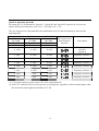
U-00:Output Frequency
U-00 is used to display the message of reference frequency during stop or to displays the output frequency
during running. It also can be set by U-13 to determine the desired direction of the motor. (Forward Run
or Reverse Run).
User can use potentiometer of digital operator to set the frequency reference (U-04=1). It also can be done
keys.
by pressing
Related Constants:
U-04 [Frequency Mode]:Select the frequency setting methods (Digital operator-1, digital operator-2,
terminal Vs, terminal Is, terminal Vs+Is, RS485 communication port.)
A-20 [Max. Output Frequency]
C-01 to C-10 [Analog Reference Inputs]:Scaling the analog input signals (Vs and Is) for frequency
reference and potentiometer of digital operator.
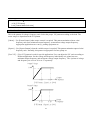
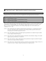
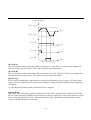
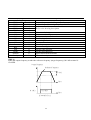
U-01:Acceleration Time
U-02:Deceleration Time
The reference frequency for accel/ decel is determined by b-70 when accelerating or decelerating.
If b-70 is set to “Maximum Frequency”, the acceleration time is the time taken by the motor to reach
A-20 [Maximum Output Frequency] from 0 Hz. The deceleration time is the time taken by the motor to
reach 0 Hz to A-20 [Maximum Output Frequency].
When b-70 is set to “Delta Frequency”, the acceleration and deceleration time is the time taken to reach
targeted frequency (instead of the maximum frequency) from current frequency.
The acceleration and deceleration time can be selected to preset step acceleration/ deceleration time via
multi-function input terminal. Set the multi-function inputs (S6, S7, S8) to “XCEL-L”, “XCEL-M”,
“XCEL-H” respectively. The step acceleration/ deceleration time can be set in C-25 to C-38 according to
the binary inputs of the S6, S7, S8.
31
Output Frequency
Max.Freq.
Time
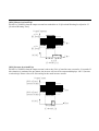
Acc.Time
Dec.Time
Related Constants:
A-20 [Max. Output Freq]
b-70 [Reference Freq. for Accel/Decel]
b-71 [Accel/Decel Time Scale]
C-12 to C-14:[Multi-function Input Terminal S6, S7, S8]
C-25 to C-38:Select the Step accel/ decel time in C-25 to C-38 by terminal S6, S7, S8.
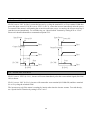
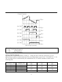
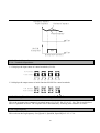
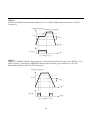
U-03:Drive Mode (Run/stop Method)
Setting Range
Select
Display
Description
0
Run/ stop is controlled by
(Factory Default)
1
2
3
,
keys of digital operator.
Run/ stop is controlled by control terminals S1, S2 and terminal COM
for S1/S2-1 pattern.
Run/ stop is controlled by control terminals S1, S2 and terminal COM
for S1/ S2-2 patttern.
Run/ stop is controlled by RS485communication port, MODBUS-RTU
communication format.
32
Output Frequency
Output Frequency
Forward
Forward
Time
Time
Reverse
S1-COM
S2-COM
Reverse
ON
ON
Forward Run
S1-COM
Reverse Run
S2-COM
[U-03=1,S1/S2-1 Mode]
Run/Stop
ON
ON
Direction
[U-03=2,S1/S2-2 Mode]
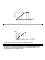
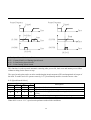
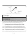
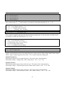
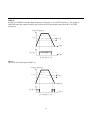
U-04:Frequency Mode (Frequency Setting Method)
Select the source of frequency setting.
Select
Setting Range
Display
Description
Frequency reference is set by pressing
keys of digital
0
operator. Press
key to store the setting value in U-00.The inverter
(Digital Operator-1)
does not change the output frequency value before pressing
key.
1
Frequency reference is set by potentiometer of digital operator.
(Digital Operator-2)
(Factory Default) Refer to C-01 to C-05 for scaling the potentiometer single.
2
Input the frequency reference 0~+10V by external terminal Vs.
(Vs)
Refer to C-01 to C-05 for scaling the terminal Vs signal.
3
Input the frequency reference (4~20mA) by external terminal Is.
(Is)
Refer to C-06 to C-10 for scaling the terminal Is signal.
Input the frequency reference (0~10V, 4~20mA) to the terminal Vs, Is
4
at the same time. The signal Vs overwrites the signal Is. (Signal Vs plus
(Vs+Is)
signal Is)
5
(RS-485)
Run/ stop is controlled by RS485communication port, MODBUS-RTU
communication format.
33
Output Frequency
Max.Freq.
Freq. Setting Range
0V
10V
Analog Signal Input(Vs)
[U-04=2 Vs Mode]
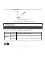
Output Frequency
Max.Freq.
Freq. Setting Range
4mA
20mA
Analog Signal Input(Is)
[U-04=3 Is Mode]
Output Frequency
Max. Freq.
Freq. Setting Range
0V+4mA 10V+20mA
Analog Signal Input(Vs+Is)
[U-04=4 Vs+Is Mode]
34
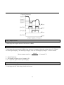
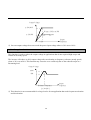
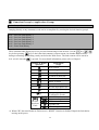
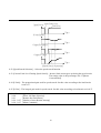
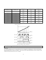
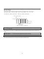
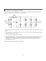
U-05:Step Frequency 1
U-06:Step Frequency 2
U-07:Step Frequency 3
Binary Combination of multi-function terminal S6, S7, S8
Terminal
Terminal
Terminal
S6–COM
S7-COM
S8-COM
Speed-L
Speed-M
Speed-H
C-12=0
C-13=1
C-14=2
The signal source
from frequency
reference.
Description
0 (off)
0 (off)
0 (off)
Select frequency
reference. (Speed 0)
1 (on)
0 (off)
0 (off)
Frequency reference 1
0 (off)
1 (on)
0 (off)
Frequency reference 2
1 (on)
1 (on)
0 (off)
Frequency reference 3
0 (off)
0 (off)
1 (on)
Frequency reference 4
1 (on)
0 (off)
1 (on)
Frequency reference 5
0 (off)
1 (on)
1 (on)
Frequency reference 6
1 (on)
1 (on)
1 (on)
Frequency reference 7
Related Constants:
C-12 to C-14 [Select the multi-function input terminal S6, S7, S8]
C-17 [Filtering Time Constant for multi-function input terminal]:Adjust the filtering time of input terminal
to eliminate contact noise.
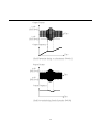
35
Output Frequency
Speed 0
Speed 3
Speed 2
Speed 1
Time
S6-COM
ON
ON
S7-COM
Time
ON
Time
S8-COM
Time
[Step Frequency Output]
U-08:Output Current
U-08 displays the output current of the inverter in RMS.
U-09:Motor Speed
U-09 displays the motor speed in RPM when the motor is running. Adjust the setting value of b-74[Gain
for motor speed display]. The meaning of display value can be changed. (Example:r/min or m/min)
120 × F
Motor constant rotation =
P
F:Output frequency
P:The number of motor poles (Constant b-31)
b-74:Adjust the gain of motor speed display.
U-10:DC Link Voltage
U-10 displays the DC link voltage inside the inverter.
36
× Constant b-74
U-11:b-73 Selection Display
There are 3 types of constant in b-73 as bellow:
b-73=0 displays the inverter output voltage (Factory Default)
b-73=1 displays the inverter output watt.
b-73=2 displays the inverter output torque.
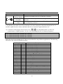
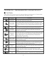
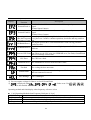
U-12:Fault Display
U-12 displays the current fault (trip) status of the inverter. Use the
key,
key and
key to
check the fault contents(s), output frequency fault, output current trip, or whether the inverter is
accelerating, decelerating, or in constant speed at the time the fault occurrs.
The fault content(s) will be auto-stored in b-01 to b-05 when the
key is pressed.
Refer to Chapter 5 – Troubleshooting & Maintenance for detail content(s).
Display of digital
operator
Fault Status
(Trip)
Over current
Over voltage
Under voltage
Heat sink overheat
Electronic thermal trip
Motor overload
Inverter overload
Inverter input phase loss
Inverter
hardware
fault
Inverter output phase loss
Emergency stop
(Terminal S3 closed.)
CPU EEPROM error
Inverter cooling fan fault
CPU error
Ground Fault
NTC damage
※ The inverter will not reset when CPF5 fault (Inverter hardware fault) occurs. Repair the fault before
turning on the power.
Related Constants:
b-01 to b-05 [Fault History up to 5]
b-06
[Erase Fault History]
37
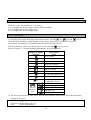
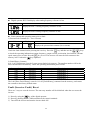
U-13:Motor Direction Set
7-segment Display
F
r
Description
Forward Run Direction
Reverse Run Direction
A---:A Group selection
b---:b Group selection
C---:C Group selection
38
█
Function Group A (Standard Group)
A-00:Jump to Desired Code #
Jumping directly to any constant(s) code can be accomplished by entering the desired function group A.
A-03:Run Prevention
This function prevents reverse run of the motor. This function may be used for loads that rotate only in
one direction such as mills and pumps.
Constant Code
Description
0
Forward and reverse run is available.
None
1
Forward run is prohibited.
Forward Prohibition
2
Reverse run is prohibited.
Reverse Prohibition
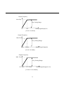
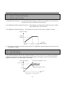
A-05:Acceleration Pattern
A-06:Deceleration Pattern
Different combinations of acceleration and deceleration patterns can be selected according to different
applications.
Constant Code
Description
0
(Factory Default) This is a general pattern for fixed torque control output.
Linear
This pattern allows the motor to accelerate and decelerate smoothly. The
1
actual acceleration and deceleration time is longer about 40% than the time
S-Curve
set in U-01 and U-02.
2
This pattern provides more efficient control of accel/ decel in typical
U-Curve
winding machine application.
The inverter reduces acceleration time by accelerating with its 150%
rated current and reduces deceleration time by decelerating with a DC
95% voltage rate of of its over-voltage trip level.
3
Appropriate application:To make max. output capacity of inverter and
Minimum
motor.
Inappropriate application:The current limit function may extend the time
for loads that have high inertia such as mills.
4
The inverter accelerates with current rate of 120% of its rated current and
Optimum
decelerates with voltage rate of 93% of its over-voltage trip level.
39
NOTE:
1. When selecting the “Minimum” or “Optimum”, the U-01 [Accel Time] and U-02 [Decel Time] is
ignored.
2. “Minimum” and “Optimum” functions can be operated when the load inertia is less than 10 times the
motor inertia. (b-37)
3. “Optimum” is best effective when the motor capacity is smaller than inverter capacity.
4. “Minimum” and “Optimum” cannot be used in going down of a lifting elevator.
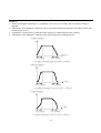
Output Frequency
Time
Acc. Pattern
Dec. Pattern
Accel/Decel Pattern:'Linear' [A-05=0 ; A-06=0]
Output Frequency
Time
Acc. Pattern
Dec. Pattern
Accel/Decel Pattern:'S-Curve' [A-05=1 ; A-06=1]
Output Frequency
Time
Acc. Pattern
Dec. Pattern
Accel/Decel Pattern:'U-Curve' [A-05=2 ; A-06=2]
40
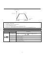
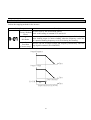
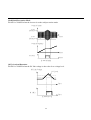
A-07:Stop Mode
Selects the stopping method for the inverter.
Setting Range
Description
0
Inverter stops by the deceleration pattern.
(Factory Default)
Refer to the setting of constant U-02 and A-06.
Decel
Inverter stops with DC injection braking. Inverter outputs DC voltage to
1
make braking torque in motor winding when the frequency reachs the
DC-Brake
DC injection braking frequency set in A-08 during decelerating.
2
Inverter cuts off its output voltage and frequency immediately when the
Free-Run
stop signal is entered. (S1-COM OFF)
(Coast to stop)
Output Frequency
Time
Output Voltage
Time
Stop Command
S1-COM
ON
Time
Stop Mode:'Decel' (A-07=0)
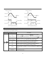
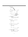
41
Output Frequency
A-08
Time
Output Voltage
t1:A-09
t2:A-11
A-10
Time
Stop Command
S1-COM
ON
Time
Stop Mode:'DC-Brake' (A-07=1)
Output Frequency
Output Cutoff
Time
Output Voltage
Output Cutoff
Time
Stop Command
S1-COM
ON
Time
Stop Mode:'Free-Run' (A-07=2)
42
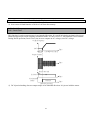
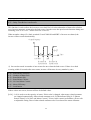
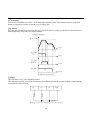
A-08:DC Injection Braking Frequency
A-09:DC Injection Braking On-delay Time
A-10:DC Injection Braking Voltage
A-11:DC Injection Braking Time
These functions are for adding a DC voltage into motor windings then, the motor will stop working
rapidly. Selecting “DC-Brake” in A-07 (A-07=1) activates functions of constant A-08 to A-11.
A-08 [DC Injection Braking Frequency]:Inverter starts to output DC voltage to motor frequency during
decelerating.
A-09 [DC Injection Braking On-delay Time]:Inverter output blocking time before DC injection braking.
A-10 [DC Injection Braking Voltage]:Adding the DC voltage to the motor windings. The setting value
of A-09 is related it of b-33 [motor rated current].
A-11 [DC Injection Braking Time]:The time from DC current to the motor.
Output Frequency
A-08
Time
Output Voltage
t1:A-09
t2:A-11
A-10
Time
Stop Command
S1-COM
ON
Time
[DC Injection Braking Operation]
43
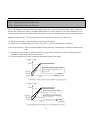
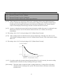
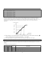
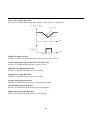
A-12:Starting DC Injection Braking Voltage
A-13:Staring DC Injection Braking Time
Inverter is adding A-12 [Starting DC injection braking voltage] and A-22 [Minimum output frequency]
into the motor, and holding DC injection time set by in b-13.
Output Frequency
Min. Output Freq. A-22
Time
Output Voltage
A-12
Output Current
Time
t1:A-13 Starting DC Injection
Braking Time]
Time
Run Command
S1-COM
ON
Time
[Starting DC Injection Braking Operation]
Related Constant:
b-33 [Motor Rated Current] {RMS}
※ When A-12 or A-13 is set to “0”, the DC injection braking function cannot work.
※ When multi-function terminals (S6,S7,S8) is set as the “DC injection function during stop”(C-12=6 or
C-13=6 or C-14=6), the setting value of A-12 is used as “DC injection function during stop” for output
voltage level.
44
A-20:Maximum Frequency
A-21:Maximum Voltage Output Frequency
A-22:Minimum Output Frequency
A-20 [Maximum Frequency]:The maximum output frequency of the inverter. Make sure this maximum
frequency does not exceed the motor rated speed.
A-21 [Maximum Voltage Output Frequency]:The frequency of output rated voltage for inverter. When
using a 50Hz motor, set it to 50Hz.
A-22 [Minimum Output Frequency]:The frequency where the inverter starts to output its voltage.
Output Voltage
Rated
Voltage
A-22
A-21
A-20
Output
Frequency
※ If frequency reference set point is set lower than A-22 [Minimum output frequency], the inverter will
not output the voltage.
A-23:Frequency Limit Selection
A-24:Low Limit Frequency
A-25:High Limit Frequency
A-23 selects the limits for the inverter operating frequency. If A-23 is set to “Yes”, the inverter operates
within the upper and lower limit setting. The inverter operates at the upper or the lower limit when the
frequency reference is over the frequency limit range.
Output Frequency
Reference Frequency Curve
Max. Freq.
A-24
Output Frequency Curve
A-25
Time
[Freq. limit : Yes,A-23=1]
45
A-26:Manual/Auto Boost Selection
A-27:Torque Boost in Forward Direction
A-28:Torque Boost in Reverse Direction
These functions are used to increase the starting torque at low speed by increasing the output voltage of
the inverter. If the boost value is set higher than requested, it may cause the over-current trip due to over
starting current. Increase the boost value when there is excessive distance between the motor and inverter.
[Manual Torque boost]:The forward and reverse torque boost is set in A-27 and A-28.
※ Torque boost value is the percentage of inverter rated voltage.
※ When A-29 [Volts/Hz Pattern] is set to “User V/F” (A-29=2), this function is disabled.
[Auto Torque Boost]:Inverter outputs higher starting torque by automatically boosting according to the
load.
※ Auto torque boost is only available for the first group motor constants. For the second group motor
constants, manual torque boost must be used.
※ The auto torque boost value is added to the manual torque boost value.
Output Voltage
100%
Manual
Boost
Value
Forward and Reverse direction
(Set the same value for A-27
and A-28)
Output
Frequency
A-21
[Constant Torque Loads:Conveyor,Moving Equip.etc.]
Output Voltage
100%
Forward Direction-Motoring
(Set A-27 to a value)
Manual
Boost
Value
Reverse Direction-Generating
(Set A-28 to '0')
Output
Frequency
A-21
[Ascending and Descending Loads:Parking,Hoist etc.]
46
Related Constants:
A-29 [V/F Pattern]
b-40 [Control Mode Selection]
A-29:Volts/Hz Pattern
This is the pattern of voltage/ frequency ratio. Select the proper V/F pattern according to the load. The
motor torque is dependent on the V/F pattern.
[Linear]:Use [Linear Pattern] when torque control is required. This pattern maintains a linear volts/
frequency ratio from minimum output frequency to maximum voltage output frequency.
Appropriate applications are convey, parking equipment etc.
[Square]:Use [Square Pattern] when the variable torque is required. This pattern maintains squared volts/
frequency ratio. Normally, this pattern is appropriate for fans, pump etc.
[User V/F]:[User V/F] pattern is used for special applications. User can adjust the V/F ratio according to
different application. Set the voltage and frequency individually at 4 points between
minimum output frequency and maximum voltage output frequency. The 4 points of voltage
and frequency are set in A-30 to A-37 separately.
Output Voltage
100%
A-21
A-20
[V/F Pattern : 'Linear' ; A-29=0]
Output
Frequency
Output Voltage
100%
A-21
A-20
[V/F Pattern : 'Square' ; A-29=1]
47
Output
Frequency
Output Voltage
100%
A-37
A-35
A-33
A-31
A-30 A-32 A-34 A-36
A-21 A-20
Output
Frequency
[V/F Pattern : 'User V/F' ; A-29=2]
A-30 ~ A-37:User V/F Frequency and Voltage
These functions are available only when “User V/F” is selected in A-29 [V/F Pattern]. User can make
custom V/F pattern by setting four points between A-22 [Minimum Output Frequency] and A-21
[Maximum Voltage Output Frequency].
Output Voltage
100%
A-37
A-35
A-33
A-31
A-30 A-32 A-34 A-36
A-21
[User V/F ; A-29=2]
Output
Frequency
※ When the “User V/F” is selected, the torque boost of A-26 to A-28 is disabled.
A-38:Output Voltage Adjustment
This function is used to adjust the output voltage of the inverter. When using a motor that has a lower
rated voltage than the power input voltage, this function is useful. When this is set at 100%, inverter
output voltage becomes the power input rated voltage.
48
Output Voltage
A-38=100%
When A-38 Set to 50%
A-38=50%
Output
Frequency
A-21
※ Inverter output voltage does not exceed the power input voltage when A-38 is set at 110%.
A-39:Energy Save Level
This function is used to reduce the output voltage in applications that do not required high torque and
current at its steady speed.
The inverter will reduce its 20% output voltage after accelerating to frequency reference (steady speed)
when A-39 is set at 20%. This function may cause the over-current trip due to the reduced torque in a
fluctuating load.
Output Voltage
100%
80%
Reference Frequency
Output
Frequency
[A-39=20%]
※ This function is not recommended for a large load or for an application that need frequent acceleration
and deceleration.
49
A-50:Electronic Thermal (Motor i2t) Selection
A-51:Electronic Thermal Level for 1 Minute
A-52:Electronic Thermal Level for Continuous
A-53:Electronic Thermal Characteristic (Motor type) Selection
[A-50]:These functions are to protect the motor from overheating without using additional thermal.
Inverter calculates the temperature rise of the motor by using several constants and determines
whether the inverter output current may cause the motor overheating or not. Inverter cuts its
output off and displays fault message when the electronic thermal is activated.
[A-51]:Inverter is dependent on motor rated current to determine whether the motor is overheated or not.
When motor current is set in 150% motor rated current for over 1 minute, inverter trips
immediately.
※ The setting value of A-51 is the percentage of b-33 [Motor Rated Current].
[A-52]:This is setting current at which the motor can run continuously. Generally, the value is set at
100% that the setting percentage is set in b-33 [Motor Rated Current]. This value must be smaller
than A-51.
※ The setting value of A-52 is the percentage of b-33 [Motor Rated Current].
Load Current[%]
A-51
A-52
1 minute
2
[Motor I t Characteristic Curve]
Trip Time
[A-53]:In order to make the electronic thermal function (Motor I²t) work correctly, the motor cooling
method must be selected correctly according to the type of motor.
[Self-cooling]:The motor shaft is connected with a cooling fan directly. Cooling effects will reduce
when the motor is running at low speeds. The motor current is decreases as the motor
speed decrease.
50
[Forced-cooling]:Motor that uses a separate motor to power a cooling fan. This cooling method is not
effected by variable motor speed.
Output Current
Forced-Cooling
100%
95%
65%
Self-Cooling
20Hz
60Hz
[Output Current Decreasing Curve]
※ Despite the motor current changing frequently due to load fluctuation or acceleration and deceleration,
the inverter calculates the I²t and accumulates the value to protect the motor.
Related Constant:
b-33 [Motor Rated Current]
A-54:Overload Warning Level
A-55:Overload Warning Time
The inverter outputs an alarm signal A-55 [Overload Warning Time] when the output current has reached
A-54 [Overload Warning Level]. The alarm signal persists for the A-55 even if the current has become the
level below the A-54.
Multi-function output terminal (M1-M2) is used as alarm signal output. To output the alarm signal, set
C-44 [Multi-function Output Terminal M1-M2 Selection] to “OL1” (C-44=5)
※ Inverter is not tripped at this function and continue its operation function. Terminal M1-M2 only
outputs an alarm signal when C-44=5.
※ The setting value of A-54 is the percentage of b-33 [Motor Rated Current]
51
Output Current
A-54
[OL level]
Time
A-54
[OL level]
M1-M2
ON
Time
t1:A-55[Overload Warning Time]
[Overload Warning]
Related Constants:
b-33 [Motor Rated Current]
C-44 [Multi-function Output]
A-56:Overload Trip Selection
A-57:Overload Trip Level
A-58:Overload Trip Delay Time
Inverter cuts off its output and displays fault message when the output current persists over the A-57
[Overload Trip Level] for the time of A-58 [Overload Trip Time]. This function protects the inverter and
motor from abnormal load conditions.
※ The setting value of A-57 is the percentage of b-33 [Motor Rated Current].
52
Output Current
A-57
[OLT level]
Time
A-57
[OLT level]
A-58 [Overload Trip Delay Time]
Output Frequency
Overload Trip
Time
[Overload Trip Operation]
Related Constant:
b-33 [Motor Rated Current]
A-59:Stall Prevention Mode Selection (Bit set)
A-60:Stall Prevention Level
This function is used to protect the motor by reducing the inverter output frequency until the motor current
decreases below the stall prevention level. This function can be selected in any condition acceleration,
steady speed, and deceleration via bit combination.
※ The setting value of A-60 is the percentage of b-33 [Motor Rated Current].
A-59 [Stall Prevention Mode Selection]
Setting Range
3rd bit 2nd bit 1st bit
0
0
1
0
1
0
1
0
0
A-59
001
010
100
Description
Stall Prevention during Acceleration
Stall Prevention during Steady Speed
Stall Prevention during Deceleration
When A-59 is set to “111”, stall prevention is enabled during accelerating, steady speed and decelerating.
※ The acceleration and deceleration time may take longer than the time set in U-01, U-02 when Stall
Prevention is selected.
※ If stall prevention status persists, inverter may stop during acceleration.
Related Constant:
b-33 [Motor Rated Current]
53
Output Current
A-60
[Stall level]
Time
A-60
[Stall level]
Output Frequency
Time
[Stall Prevention during Acceleration(A-59=001)]
Output Current
A-60
[Stall level]
Time
A-60
[Stall level]
Output Frequency
Time
[Stall Prevention during Steady Speed(A-59=010)]
54
DC Link Voltage
390VDC or
680VDC
Time
Output Frequency
Time
[Stall Prevention during Deceleration(A-59=100)]
A-99:Return Code
55
■
Function Group b (Application Group)
b-00:Jump to Desired Constant Code #
Jumping directly to any constant(s) code can be accomplished by entering the desired function group b.
b-01:Previous Fault History 1
b-02:Previous Fault History 2
b-03:Previous Fault History 3
b-04:Previous Fault History 4
b-05:Previous Fault History 5
b-06:Erase Fault History
These constant codes display up to five previous fault message of the inverter. Use the
key,
key before pressing
key to check the fault content(s), output current. Or whether the inverter is
during accelerating, decelerating, steady run before the fault occurs. The fault content will be stored in
b-01 to b-05 when the
is pressed. For more detail information, please refer to Chapter 5.
Display of digital
operator
Fault Status
(Trip)
Over current
Over voltage
Low voltage
Overheat on heat sink
Electronic thermal trip
Motor overload
Inverter overload
Inverter input phase loss
Inverter
Hardware
Fault
Inverter output phase loss
Emergency stop
(Terminal S3 closed.)
CPU EEPROM error
Inverter cooling fan fault
CPU error
Ground Fault
NTC damage
※ When CPF5 (Inverter Hardware Fault) occurs, “RESET” function is disabled. Repair the fault before
turning on the power.
56
Related Constant:
U-12 [Fault Display]:Displays current fault status.
※ b-06 erases all fault histories of b-01 to b-05 from the memory.
b-07:Dwell Frequency
b-08:Dwell Time
This function is used to output torque in an intended direction. It is useful in hoisting mechanical device to
obtain enough torque before releasing mechanical brake. If b-08 is set at “0”, this function is not available.
During Dwell operation (Dwell Time), the inverter outputs an AC voltage, not a DC voltage.
Output Frequency
b-07
Time
t1:b-08[Dwell Time]
Output Current
Time
Run Command
S1-COM
Mechanical
Brake
ON
Release
Time
Time
[Dwell Operation]
※ DC injection braking does not output torque to an intended direction. It is just to hold the motor.
57
b-10:Frequency Jump Selection
b-11:Jump Frequency 1 (Low)
b-12:Jump Frequency 1 (High)
b-13:Jump Frequency 2 (Low)
b-14:Jump Frequency 2 (High)
b-15:Jump Frequency 3 (Low)
b-16:Jump Frequency 3 (High)
To prevent undesirable resonance and vibration on the mechanical structure, this function avoids the
potential resonance frequency from running process. Three different jump frequency ranges can be set. No
jump frequency happening during accelerating and decelerating. It only occurs during continuous
operation.
Output Frequency
A-20
b-12
b-11
b-14
b-13
b-16
b-15
10Hz
20Hz
30Hz
Reference
Frequency
※ When frequency is set in jump frequency, the output frequency goes to the frequency marked by “●”
symbol, and then jump to the frequency marked by “○” by symbol.
※ If one jump frequency is required, set all the jump frequency range to the same range.
b-19:Input/Output Phase Loss Protection (Bit Set)
This function is used to cut the inverter output off in case of phase loss in either input power or inverter
output.
b-19 [Phase Loss Protection Select]
Setting Range
2nd bit
1st bit
0
0
0
1
1
0
1
1
b-19
00
01
10
11
Description
Phase loss protection does not work
Starting the output phase loss function.
Starting the input phase loss function.
Starting the input/ output phase loss.
58
b-20:Power ON Start Selection
If b-20 is set to “NO” (b-20=0), restart the inverter by cycling the terminal S1 or S2 to terminal COM after
power has been restored. If b-20 is set to “YES” (b-20=1), restart the inverter immediately after the power
is restored. If the motor is still rotating due to inertia at the time power is restoring, the inverter may trip if
start the inverter immediately. To avoid the trip, use “Speed Search” function by setting b-22 to “1xxx”.
Please refer detail information to constant description b-22.
Input Power
Input Power
Power ON
Power ON
Time
Time
Output Frequency
Output Frequency
Time
No Effect
S1-COM
ON
Time
Start
ON
Start
S1-COM
Time
[b-20=0]
ON
Time
[b-20=1]
b-21:Restart After Fault Reset
If b-21 is set to “YES” (b-21=1), inverter will restart immediately after the reset terminal signal (S4-COM
ON) is shown.
If b-21 is set to “NO” (b-21=0), inverter will restart after reset terminal (S4-COM ON) and have terminal
S1 or S2 cycling the terminal COM.
The inverter may trip if the motor is rotating by inertia at the time the inverter restarts. To avoid the trip,
use “Speed Search” function by setting b-22 to “xx1x”
59
Output Frequency
Output Frequency
Tripped
Tripped
Time
Time
No Effect
Start
Start
S1-COM
ON
ON
S4-COM
ON
S1-COM
Time
S4-COM
Time
[b-21=0]
ON
Time
ON
Time
[b-21=1]
b-22:Speed Search Selection (Bit Set)
b-23:Current Limit Level During Speed Search
b-24:P Gain During Speed Search
b-25:I Gain During Speed Search
This function is used to permit automatic restarting after power ON, fault reset and instant power failure
without waiting for the motor to stop.
The speed search gain can be set after considering the inertia moment (GD²) and magnitude of torque of
the load. To make sure b-22 operate correctly, b-37 [Load Inertia] must be set at the correct value.
b-22 [Speed Search Select]
th
4 bit
0
0
Setting Range
3rd bit 2nd bit
0
0
0
0
1st bit
0
1
0
0
1
0
0
1
1
0
0
0
0
0
Description
Speed search function does not work.
Speed search during accelerating.
Speed search during a fault reset restarting (b-21) and auto restarting
(b-26).
Speed search during instant power failure restarting.
Speed search during power ON starting (b-20)
When b-22 is set to “111”, speed search performs under all the conditions.
60
Input Power Input Power loss
Power On
Time
Motor Speed
Time
Output Frequency
Time
Output Voltage
Time
[Speed Search Operation]
b-22 [Speed Search Selection]:Select the speed search function.
b-23 [Current Limit Level During Speed Search]:Inverter limit current goes up during the speed search.
The setting value is the percentage of b-33 [Motor
Current Rated].
b-24 [P Gain]:The proportional gain used for speed search. Set this value according to the load inertia
set in b-37.
b-25 [I Gain]:The integral gain used for speed search. Set this value according to load inertia set in b-37.
Related Constant:
b-20
[Power ON Start Selection]
b-21
[Restart after Fault Reset]
b-26 ~ b-27 [Number of Auto Restart Attempt]
b-30 ~ b-37 [Motor Constants]
61
b-26:Number of Auto Restart Attempt
b-27:Delay Time Before Auto Restart
This function is used to allow the inverter to reset itself for b-26 selected number of times after a fault is
reset. Inverter automatic restart after the fault occurs. In order to use the speed search function during auto
restarting, set b-22 to “xx1x”. Please refer to b-22 to b-25.
When an under voltage (Uv) fault, terminal S3 and COM ON and IGBT of inverter are shorted, the
inverter will not restart automatically.
Output Frequency
t:b-27
Time
1st Fault
2nd
Restart with
Speed Search
Reatsrt with
Speed Search
※ Inverter decreased its number of auto restart for once when the fault occurs. If there is no fault
occuring within 30 seconds after auto restart, inverter will increase its retry number by once.
b-30:Rated Motor Selection
b-31:Number of Motor Pole
b-32:Rated Motor Slip
b-33:Rated Motor Current
b-34:No Load Motor Current
b-36:Motor Efficiency
b-37:Load Inertia
If these values are not set, inverter will use its default values.
[b-30]:b-30 is used to set the capacity of motor. If this value is changed, other motor related constants
are changed automatically. Other related constants are b-32 [Motor Rated Slip], b-33 [Motor
Rated Current], b-34 [No Load Motor Current]. To have better control performance, please refer
to adjustable setting value of other related constant codes if user knows the motor constants.
62
[b-31]:This constant is related to U-09, motor speed display. If user sets the value to 2, then U-09
displays 3600rpm at 60Hz output frequency, not 800rpm at 60Hz output frequency. (Refer to
motor nameplate)
[b-32]:This is used in “Slip Compensation” control. If user set this value incorrectly, motor may stall
during slip compensation control. (Refer to motor nameplate)
[b-33]:This constant value must be set correctly as it is very important constant. This value is referred by
many other constants. (Refer to motor nameplate)
[b-34]:This constant is only displayed when “Slip Compensation” is selected in b-40 [Control Method].
This function is used to maintain constant motor speed. To keep the motor speed constant, the output
frequency varies within the limit of slip frequency set in b-32 according to the load current. For example,
inverter increases output frequency higher than the reference frequency to increase the motor speed when
the motor speed decreases below the reference speed (frequency) due to a heavy load.
Output current – No load current
Delta
× Rated Slip
=
Frequency
Rated current – No load current
Inverter output frequency = Reference frequency + Delta frequency.
[b-36]:This value is used to calculating the output wattage when b-72 is set to “Watt”.
[b-37]:This constant is used for sensorless control, minimum Accel/ Decel, optimum Accel/ Decel and
speed search. For better control performance, this value must be set as exact as possible.
Set to
0:Loads inertia less than 10 times of motor inertia.
1:Loads inertia is 10 times of motor inertia.
2:Loads inertia bigger than 10 times of motor inertia.
b-39:Carrier Frequency
[b-39]:This constant affects the audible sound of the motor, noise emission from the inverter, inverter
temperature, and leakage current. If the ambient temperature where the inverter is installed is high
or other equipment may be affected by potential inverter noise, decrease the setting value of b-39.
At the same time, adjusting carrier frequency can also avoid induced resonance in the machine
and motor.
※ If this value must be higher than 3 kHz, decreases inverter load current by 5% per increases 1 kHz.
63
b-40:Control Method Selection
Select control method of the inverter.
Setting Range
Description
0
V/F Control
V/F
1
Slip compensation operation
Slip compensation
2
PID feedback control
PID
[V/F]:It maintains the same voltage/ frequency ratio constant. It is recommended to use the torque boost
function when a greater starting torque is requested.
Related Constant:b-26 ~ b-28 [Torque Boost]
[Slip Compensation]:This function is used to maintain constant motor speed. To keep the motor speed
constant, the output frequency varies within the limit of slip frequency set in b-32
according to the load current. For example, when the motor speed decreases below
the reference speed (frequency) due to a heavy load, the inverter will increase its
output frequency to be higher than the reference frequency to increase the motor
speed.
Output current – No load current
Delta
× Rated Slip
=
Frequency
Rated current – No load current
※ For better control performance, the motor constants must be set correctly.
Related Constant:b-30 ~ b-37 [Motor Parameters]
[PID]:For HVAC or pump applications, the PID control can be used to adjust the actual output by
comparing a feedback value with setting value of inverter. The “Set-point” can be in the form of
speed, temperature, pressure, flow level, etc. All of the set-point and feedback signal are provide
to the inverter analog input terminals Vs or Is. Inverter outputs a adjust frequency value to motor
after PID controller is calculated. Please refer to b-50 to b-54 for more detail.
Related Constant:b-50 ~ b-54 [PID Feedback]
64
b-50:PID Feedback Signal Selection
b-51:P Gain for PID Control
b-52:I Gain for PID Control
b-53:D Gain for PID Control
b-54:Limit Frequency for PID Control
[PID]:For HVAC or pump applications, the PID control can be used to adjust the actual output by
comparing a feedback value with setting value of inverter. The “Set-point” can be in the form of
speed, temperature, pressure, flow level, etc. All of the set-point and feedback signal are provided
to the inverter analog input terminals Vs or Is. Inverter outputs a adjust frequency value to motor
after PID controller is calculated. Please refer to b-50 to b-54 for more detail.
※ PID control can be manual operation temporarily by setting multi-function input terminals (S6~S8) to
“Open Loop”. The inverter will change to manual operation from PID control when this terminal is
ON, and change back to PID control when this terminal is OFF.
[b-50]:Select the feedback signal for PID control. It can be set one of “Vs”, “Is” according to the signal
(voltage or current).
[b-51]:Set the proportional gain for PID control.
[b-52]:Set the integral gain for PID control.
[b-53]:Set differential gain for PID control.
[b-54]:This is the frequency at which the output frequency is limited during PID control.
U-01
U-02
Reference
Set-point(U-04)
Keypad-1
err
-VR
Vs
C-12~C-14
b-51
b-52
b-53
M
b-54
Is
Process
Vs+Is
4~20mA
0~10V
Feedback
Transducer
b-50
[PID Control Block Diagram]
[P Control]:This is to compensate the error of a system proportionally. This function is used to make the
controller response fast for an error. When P control is used alone, the system is easily
affected by an external disturbance during steady state.
65
[I Control]:This is to compensate the error of system by integrally. This is used to compensate the steady
state error by accumulating them. Using this control alone makes the system unstable.
[PI Control]:This control method works stable in many systems. If “D Control” is added to this system,
then it becomes the 3rd order system. In some systems this may lead to system instability.
[D Control]:Since the D control uses the variation ratio of error, it has the merit of controlling the error
before the error is too large. The D control requires a large control quantity at start, but has
the tendency of increasing the stability of the system. This control does not affect the steady
state error directly, but increases the system gain because it has an attenuation effect on the
system. As a result, the differential control component has an effect on decreasing the
steady state error. Since the D control operates on the error signal, it cannot be used alone.
Always use it with the P control or PI control.
Related Constants:
U-04
[Frequency Mode]
b-40
[Control Method]
C-01 ~ C-10 [Analog Signal Scaling]
b-70:Reference Frequency for Accel/Decel
This is the reference frequency for acceleration and deceleration. If a decided Accel/Decel time from a
frequency to a target frequency is required, set this value to “Delta freq”.
Setting Range
0
Max freq
1
Delta freq
Description
The Accel/Decel time is the time that takes to reach the maximum
frequency from 0 Hz.
The Accel/Decel time is the time that takes to reach a target frequency
from a frequency.
Related Constants:
U-01, U-02 [Accel/Decel Time]
b-71
[Accel/Decel Time Scale]
C-25 ~ C-38 [1st ~ 7th Accel/Decel Time]
b-71:Accel/Decel Time Scale
This is used to change the time scale.
66
Setting Range
0
0.01 sec
1
0.1 sec
2
1 sec
Description
The Accel/Decel time is changed by 0.01 second. The maximum setting
range is 600 seconds.
The Accel/Decel time is changed by 0.1 second. The maximum setting
range is 6000 seconds.
The Accel/Decel time is changed by 1 second. The maximum setting range
is 60000 seconds.
Related Constants:
U-01, U-02 [Accel/Decel Time]
b-70
[Reference Freq. for Accel/Decel]
C-25 ~ C-38 [1st ~ 7th Accel/Decel Time]
b-72:Power On Display
This code selects the parameter to be displayed first on keypad (U-00) when the power is turned on.
Setting Range
0
1
2
3
4
5
6
7
8
9
10
11
12
13
Description
U-00 [Reference Frequency during stop;Output Frequency during running]
U-01 [Acceleration Time]
U-02 [Deceleration Time]
U-03 [Drive Mode]
U-04 [Frequency Mode]
U-05 [Step Frequency 1]
U-06 [Step Frequency 2]
U-07 [Step Frequency 3]
U-08 [Output Current]
U-09 [Motor Speed]
U-10 [DC link Voltage]
U-11 [b-73 Selection Display]
U-12 [Fault Display]
U-13 [Motor Direction Set]
b-73:U-11 Selection Display
This constant code set the meaning of display code in U-11.
67
Setting range
0
Voltage
1
Watt
2
Torque
Description
Displays the output voltage of inverter.
Displays the output power of inverter.
Displays the output torque of inverter.
b-74:Gain for Motor Speed Display
This code is used to change the motor speed display to rotating speed (r/min) or mechanical speed
(m/min). The display is calculated by following equation.
Rotating Speed = 120 x F / P, where F = Output frequency, P = motor pole number
Mechanical Speed = Rotating speed x Motor RPM Display Gain
Related Constants:
U-00 [Output Frequency]
U-09 [Motor Speed]
b-31 [Motor Pole]
b-75:DB (Dynamic Braking) Resistor Mode Selection
Setting Range
Description
0
(None)
No external DB resistor, no DB signal.
1
(None)
2
Select external DB resistor.
(Ext. DB-R)
(Factory Default)
b-76:Duty of DB (Dynamic Braking) Resistor
%ED =
Decel. Time
(Accel. Time+Reference Freq. Operation Time+Decel. Time+Stop Time)
Set the duty of DB resistor when select external DB resistor.
68
× 100%
b-79:Software Version
Displays the software version of EI-500.
b-81:2nd Acceleration Time
b-82:2nd Deceleration Time
b-83:2nd Base Frequency
b-84:2nd V/F Pattern
b-85:2nd Forward Torque Boost
b-86:2nd Reverse Torque Boost
b-87:2nd Stall Prevention Level
b-88:2nd Electronic Thermal Level for 1 Minute
b-89:2nd Electronic Thermal Level for Continuous
b-90:2nd Motor Related Current
These functions are displayed only when any of the multifunction inputs (S6, S7, S8) is set at “2nd
function” in C-12 to C-14, then these functions are effective. When using two motors with an inverter by
exchanging them, different values can be set for the 2nd motor by using the multifunction input terminal.
Following table is the 2nd functions corresponding to the 1st functions.
2nd Functions
b-81
[2nd Acc time]
b-82
[2nd Dec time]
b-83
[2nd Base Freq]
b-84
[2nd V/F]
b-85
[2nd F-boost]
b-86
[2nd R-boost]
B-87
[2nd Stall]
B-88
[2nd ETH 1min]
B-88
[2nd ETH cont]
B-90
[2nd R-Curr]
1st Functions
U-01
[Acc. time]
U-02
[Dec. time]
A-21
[Base freq]
A-29
[V/F Pattern]
A-27
[Fwd Boost]
A-28
[Rev Boost]
A-60
[Stall Level]
A-51
[ETH 1min]
A-52
[ETH cont]
B-33
[Rated-Curr]
Description
Acceleration time
Deceleration time
Output frequency at maximum voltage
V/F pattern
Manual forward torque boost
Manual reverse torque boost
Stall prevention level
ETH level for 1 minute
ETH level for continuous
Motor rated current
69
※ The 1st functions are applied if the multi-function terminal is not defined to “2nd Function” or if it is
not ON. The 2nd function constants are applied when the multi-function input terminal set to “2nd
Function” is ON. Parameters not listed on the table above are applied to the 2nd motor as to the 1st
motor.
※ Exchange the motor connection from the 1st motor to the 2nd motor or the opposite when the motor is
stopped. Over voltage or over current fault can occur when the motor connection is exchanged during
operation.
※ The “User V/F” function of A-29 [Volts/Hz Pattern] is used for both the 1st motor and the 2nd motor.
b-91:Constant Read
b-92:Constant Write
This is useful for programming multiple inverters to have same parameter settings. The keypad can read
(upload) the parameter settings from the inverter memory and can write (download) them to other
inverters.
[b-91]
[b-92]
EI-500
EI-500
RCU-500
RCU-500
Read
ERICDRIVE R
SET
ALARM
FOR
REV
RUN
STOP
DIGITAL OPERATOR
RCU-500
ERICDRIVE R
ERICDRIVE R
SET
SET
ALARM
FOR
REV
RUN
STOP
ALARM
FOR
REV
RUN
STOP
Write
ERICDRIVE R
DIGITAL OPERATOR
RCU-500
DIGITAL OPERATOR
RCU-500
b-93:Parameter Initialize
This is used to initialize parameters back to the factory default values. Each function group can be
initialized separately.
Description
0
1
2
3
4
5
Displayed after initializing parameters.
All constant groups are initialized to factory default value.
Only Function group U is initialized.
Only Function group A is initialized.
Only Function group b is initialized.
Only Function group C is initialized.
70
SET
ALARM
FOR
REV
RUN
STOP
DIGITAL OPERATOR
RCU-500
b-94: Parameter Write Protection
This function is used to lock the constants from being changed. The lock and unlock code is “6”. Digital
operator displays “U - - 0” when unlocked and “L - - 0” when locked.
b-99: Return Code
71
█
Function Group C (Multi-function terminal constant group)
C-00:Jump to Desired Code #
Jumping directly to any constant code can be accomplished by entering the desired code number.
C-01:Filtering Time Constant for Vs Signal Input
C-02:Vs Input Minimum Voltage
C-03:Frequency corresponding to Vs Input Minimum Voltage
C-04:Vs Input Maximum Voltage
C-05:Frequency corresponding to Vs Input Maximum Voltage
This is used to adjust the analog voltage input signal when the frequency is referred by the digital operator
potentiometer or external terminal “Vs”. This function is applied when U-04 is set to “U-04=1” or “U04=2” or “U-04=4”. Reference frequency versus Analog voltage input curve can be made by four
constants of C-02 ~ C-04.
[C-01]:This is the filtering time constant for digital operator potentiometer or Vs signal input. Increase
this value if the analog signal is affected by noise causing unstable operation of the inverter.
Increasing this value makes response time slower.
[C-02]:This is the minimum voltage of the digital operator potentiometer or terminal Vs input at which
inverter outputs minimum frequency.
[C-03]:This is the inverter output minimum frequency when there is the minimum voltage (C-02) on the
digital operator potentiometer or terminal Vs.
[C-04]:This is the maximum voltage of the digital operator potentiometer output or terminal Vs input at
which inverter outputs maximum frequency.
[C-05]:This is the inverter output maximum frequency when there is the maximum voltage (C-04) on Vs
terminal or the max. voltage is output by potentiometer of digital operator.
72
Reference Frequency
C-05
C-03
C-02
C-04
Analog Voltage
Input (Vs)
[Reference Frequency vs. Analog Voltage Input,Vs(0~+10V)]
Related Constants:
U-04 [Frequency Mode]
A-20 [Maximum Output Frequency]
C-06:Filtering Time Constant for Is Signal Input
C-07:Is Input Minimum Current
C-08:Frequency corresponding to Is Input Minimum Current
C-09:Is Input Maximum Current
C-10:Frequency corresponding to Is Input Maximum Current
These functions are used to adjust the analog current input signal when the external terminal Is references
the frequency. This function is applied when U-04 is set to “Is” (U-04=3) or “Vs+Is”(U-04=4). Reference
frequency versus Analog current input curve can be made by four parameters of C-07 ~ C-10.
[C-06]:This is the filtering time constant for “Is” signal input. If the “Is” signal is affected by noise
causing unstable operation of the inverter, increase this value. Increasing this value makes
response time slower.
[C-07]:This is the minimum current of the “Is” input at which inverter outputs minimum frequency.
[C-08]:This is the inverter output minimum frequency when there is minimum current (C-07) on the “Is”
terminal.
[C-09]:This is the maximum current of the terminal “Is” input at which inverter outputs maximum
frequency.
[C-10]:This is the inverter output maximum frequency when there is the maximum current (C-09) on the
“Is” terminal.
73
Reference Frequency
C-10
C-08
C-07
Analog Current
Input (Is)
C-09
[Reference Frequency vs. Analog Current Input,Is(4~20mA)]
Related Constant:
U-04 [Frequency Mode]
A-20 [Maximum Frequency]
C-11:Criteria for Analog Input Signal Loss
This is to set the criteria for analog input signal loss when U-04 [Frequency Mode] is set to “Vs”(U-04=2),
“Is”(U-04=3) or “Vs+Is” (U-04=4). Following table shows the setting value.
Setting Range
Description
0
Does not check the analog input signal.
(Factory Default)
The inverter determines that the frequency reference is lost when the
1
analog input signal is less than half of the minimum value (C-02 or
half of x1
C-07).
2
The inverter determines that the frequency reference is lost when the
below x1
analog input signal is less than the minimum value (C-02 or C-07).
When the analog input signal is lost, inverter displays the following.
Related Constants:C-48 [Operating selection at Loss of Freq. Reference] selects the operation after
determining the loss of frequency reference. The following table shows the selection in C-48.
74
Setting Range
0
(Factory Default)
1
Free Run
2
Stop
Description
Continuous operating after loss of frequency reference.
Inverter cuts off its output after determining loss of frequency
reference.
Inverter stops by its Decel pattern and Decel time after determining
loss of frequency reference.
C-49 [Waiting Time after Loss of Freq. Reference] sets the waiting time when determining the loss of
reference signal. Inverter waits to determine the loss of a reference signal until times out.
※ C-48 and C-49 also apply when U-04 is set to “
,
key of digital operator” (U-04=0) or
“potentiometer of digital operator” (U-04=1) for determining the loss of command frequency.
C-12:Multi-function Input Terminal “S6” Selection
C-13:Multi-function Input Terminal “S7” Selection
C-14:Multi-function Input Terminal “S8” Selection
Multi-function input terminals (S6, S7, S8) can be defined for many different applications. The following
table shows the various definitions for them.
Setting Range
Speed-L
0
Speed-M
1
Speed-H
2
XCEL-L
3
XCEL-M
4
XCEL-H
5
Dc-brake
6
2nd Func
7
-Reserved8
9
-ReservedUp
10
Down
11
3-Wire
12
Ext Trip-A
13
Ext Trip-B
14
-Reserved15
Open-loop
16
-Reserved17
Analog hold
18
XCEL s~p
19
-Reserved20
Description
Multi-step speed - Low
Multi-step speed - Mid
Multi-step speed - High
Multi-accel/decel - Low
Multi-accel/decel - Mid
Multi-accel/decel - High
DC injection braking during stop
Exchange to 2nd (Motor) function
Reserved for future use
Reserved for future use
Acceleration Reference
Deceleration Reference
3-wire operation
External trip A
External trip B
Reserved for future use
Exchange between PID mode and V/F mode
Reserved for future use
Hold the analog input signal
Disable acceleration and deceleration
Reserved for future use
75
[Speed-L, Speed-M, Speed-H]
By setting S6, S7, S8 terminals to “Speed-L”, “Speed-M” and “Speed-H” respectively, inverter can
operate at the preset frequency set in U-05 ~ U-07 and C-20 ~ C-24.
The step frequencies are determined by the combination of S6, S7 and S8 terminals as shown in the
following table.
Binary Combination of multi-function terminal S6, S7, S8
Terminal
Terminal
Terminal
S6–COM
S7-COM
S8-COM
Speed-L
Speed-M
Speed-H
C-12=0
C-13=1
C-14=2
The signal source
from frequency
reference.
Description
0 (off)
0 (off)
0 (off)
Select frequency
reference.
(Speed 0)
1 (on)
0 (off)
0 (off)
Frequency reference 1
0 (off)
1 (on)
0 (off)
Frequency reference 2
1 (on)
1 (on)
0 (off)
Frequency reference 3
0 (off)
0 (off)
1 (on)
Frequency reference 4
1 (on)
0 (off)
1 (on)
Frequency reference 5
0 (off)
1 (on)
1 (on)
Frequency reference 6
1 (on)
1 (on)
1 (on)
Frequency reference 7
※ C-20 [Jog Frequency] can be used as one of the step frequencies.
※ If the “S5” terminal is ON, inverter operates to Jog frequency regardless of other terminal inputs when
the inverter has input signal on terminal S6, S7, S8.
76
Output Frequency
Time
JOG
Step Step Step Step Step Step Step Step
1
2
4
7
0
3
5
6
S6-COM
ON
S7-COM
ON
ON
ON
ON
Time
ON
S8-COM
Time
ON
S5-COM
S1-COM
S5
Time
ON
ON
Time
Time
S2-COM
ON
Time
[Multi-step Operation]
Related Constants:
U-05 ~ U-07 [Step Frequency]
C-20
[S5 Frequency]
C-21 ~ C-24 [Step Frequency]
[XCEL-L, XCEL-M, XCEL-H]
By setting S6, S7 and S8 terminals to “XCEL-L”, “XCEL-M” and “XCEL-H” respectively, up to 8
different Accel and Decel times can be used. The Accel/Decel time is set in U-01 ~ U-02 and C-25 ~ C-38.
The Accel/Decel time is determined by the combination of S6, S7 and S8 terminals as shown in the
following table.
Accel/Decel Time
Constant Code
Accel Time-0
Decel Time-0
Accel Time-1
Decel Time-1
Accel Time-2
U-01
U-02
C-25
C-26
C-27
XCEL-H
(S8)
0
OFF
0
OFF
77
XCEL-M
(S7)
0
OFF
0
OFF
XCEL-L
(S6)
0
OFF
1
ON
Accel/Decel Time
Constant Code
Decel Time-2
C-28
Accel Time-3
Decel Time-3
Accel Time-4
Decel Time-4
Accel Time-5
Decel Time-5
Accel Time-6
Decel Time-6
Accel Time-7
Decel Time-7
C-29
C-30
C-31
C-32
C-33
C-34
C-35
C-36
C-37
C-38
XCEL-H
(S8)
0
OFF
0
OFF
1
ON
1
ON
1
ON
1
ON
XCEL-M
(S7)
1
ON
1
ON
0
OFF
0
OFF
1
ON
1
ON
XCEL-L
(S6)
0
OFF
1
ON
0
OFF
1
ON
0
OFF
1
ON
Output Frequency
Time
Time Time Time Time Time Time Time Time
1
2
4
7
0
3
5
6
S6-COM
S7-COM
ON
ON
ON
ON
ON
S8-COM
S1-COM
ON
ON
ON
Time
Time
Time
Time
[Multi-accel/decel Time Operation]
Related Constant:
C-25 ~ C-38 [1st ~7th Accel/Decel Time]
[DC-Brake]
DC Injection Braking can be activated during inverter stopped by configuring one of the multi-function
input terminals (S6, S7, S8) to ‘DC-Bake’. To activate the DC Injection Braking, close the contact on the
assigned terminal while the inverter is stopped.
78
[2nd Function]
Inverter uses constants set in b-81 ~ b-89 when this terminal is ON. This function must be used when
motor is stopped to avoid over current or over voltage trip.
[Up, Down]
By using the Up and Down function, the drive can accelerate to a steady speed and decelerate down to a
desired speed by using only two input terminals.
Output Frequency
Max. Freq.
Time
S6-COM
'UP'
ON
S7-COM
'DOWN'
Time
ON
S1-COM
Time
ON
Time
[Up/Down Operation]
[3-Wire]
This function is for 3-wire start/stop control.
This function is mainly used with a momentary push button to hold the current frequency output during
acceleration or deceleration.
S1
S2
S7
COM
[Wiring for 3-wire Operation, S7 Set to '3-wire']
79
Output Frequency
Max. Freq.
Time
Max. Freq.
S7-COM
S1-COM
ON
ON
Time
Time
S2-COM
ON
Time
[3-wire Operation]
[Ext Trip-A]
This is a normally open contact input. When a terminal set to “Ext Trip-A” is ON, inverter displays the
fault (EF2) and cuts off its output. This can be used as an external latch trip.
[Ext Trip-B]
This is a normally closed contact input. When a terminal set to “Ext Trip-B” is OFF, inverter displays the
fault (EF3) and cuts off its output. This can be used as an external latch trip.
[Open-Loop]
This is used to exchange the control mode of inverter from PID mode (Close Loop) to V/F mode (Open
Loop). U-03 [Drive Mode] and U-04 [Frequency Mode] are applied when the mode has been changed to
V/F pattern.
※ This function can be used only when the inverter is stopped.
[Analog Hold]
When there is an analog input signal for frequency reference and “Analog hold” terminal is ON, inverter
fixes its output frequency regardless of the frequency reference setting value. The output frequency will be
desired value by frequency reference when the terminal is OFF. This function is useful when a system
requires constant speed after acceleration.
80
Reference Frequency
Output Frequency
Reference Frequency
Output Frequency
Time
S6-COM
'Analog hold'
ON
Time
[Analog hold Operation]
C-15:Terminal Input Status
C-16:Terminal Output Status
C-15 displays the input status of control terminals (S1~S8).
O N S ta tu s
O F F S ta tu s
S4 S3 S1 S2 S5 S8 S7 S6
C-16 displays the output status of multi-function M1-M2 for control terminals
O N S ta tu s
O F F S ta tu s
M 1 -M 2
C-17:Filtering Time Constant for Multi-function Input Terminals
This is the response time constant for terminal inputs (S1, S2, S3, S4, S5, S6, S7, S8). This is useful where
there is a potential for noise. The response time is determined by “Filtering time constant * 0.5msec”.
C-20:Jog Frequency
This code sets the Jog frequency. See [Speed-L, Speed-M, Speed-H] in C-12 ~ C-14.
81
C-21:Step Frequency 4
C-22:Step Frequency 5
C-23:Step Frequency 6
C-24:Step Frequency 7
These codes set the 4th ~ 7th step frequency. See [Speed-L, Speed-M, Speed-H] in C-12 ~ C-14.
Related Constants:
U-05 ~ U-07 [Step Frequency 1 ~ 3]
C-12 ~ C-14 [Multi-function inputs]
C-17
[Filtering Time Constant]
C-25~ C-38:1st ~ 7th Accel/Decel Time
These codes are applied when the multi-function input terminals (S6, S7, S8) select the Accel/Decel time.
See [XCEL-L, XCEL-M, XCEL-H] in C-12 ~ C-14.
Related Constants:
U-01 ~ U-02 [Accel/Decel Time]
b-70 [Reference Freq. for Accel/Decel]
b-71 [Accel/Decel Time Scale]
C-12 ~ C-14 [Multi-function inputs]
C-40:FM-FC (Frequency Meter) Output Selection
C-41:FM-FC Output Gain
FM-FC terminal displays the inverter output frequency, output current, output voltage and DC link voltage.
FM-FC output voltage range from 0V to 10V. C-41 is used to adjust the output gain.
[Output Frequency]
FM terminal outputs inverter output frequency. The output value is determined by,
FM Output Voltage = (Output freq. / Max. output freq.) × 10V × C-41 / 100
[Output Current]
FM terminal outputs output current of the inverter. The output value is determined by,
FM Output Voltage = (Present output current / Motor rated current) × 10V × C-41 / 100
[Output Voltage]
FM terminal outputs output voltage of inverter.. The output value is determined by,
FM Output Voltage = (Present output voltage / Max. output voltage) × 10V × C-41 / 100
82
[DC Link Voltage]
FM terminal outputs the DC link voltage of inverter. The output value is determined by,
FM Output Voltage = (DC link voltage / Max. DC link voltage) × 10V × C-41 / 100
※ VDC max. = 400V at 220V class;VDC max. = 800V at 440V class
FM Terminal Output
15Vpeak
Avg. 0~10V
Time
20msec(fixed)
[FM Output (FM-FC Terminal)]
C-42:FDT (Frequency Detection) Level
C-43:FDT Bandwidth
These functions are used in C-44 [Multi-function Output Terminal M1-M2 Selection]. See [FDT-#] in
C-44.
Related Constant:
C-44 [Multi-function Output Define M1-M2 Selection]
C-44:Multi-function Output define (MO-MG)
The output terminal M1-M2 is closed when the defined condition occurs.
83
Setting Range
FDT-1
FDT-2
FDT-3
FDT-4
FDT-5
OL1
OL2
Stall
OV
UV
OH
Lost Command
Run
Stop
Steady
Ssearch
Ready
Description
Output frequency arrival frequency reference.
Output frequency = setting frequency of C-42
0
1
2
3
4
5
6
7
8
9
10
11
12
13
14
17
20
Refer to the drawing description.
Motor overload trip
Inverter overload trip
Stall prevention mode detection
Over voltage detection
Low voltage detection
Overheat detection
Lost frequency command detection
Inverter running detection
Inverter stop detection
Steady speed detection
Speed search mode detection
Inverter in ready status to run
[FDT-1]
When the output frequency reaches the reference frequency (target frequency), M1-M2 terminal is
CLOSED.
Output Frequency
Reference Frequency
C-43/2
Time
M1-M2
CLOSED
Time
[C-44=0(FDT-1)]
84
[FDT-2]
M1-M2 is CLOSED when the output frequency is in C-43 [FDT Bandwidth] centered on C-42 [FDT
Frequency].
Output Frequency
Reference Frequency
C-42
C-43/2
Time
M1-M2
CLOSED
Time
[C-44=1(FDT-2)]
[FDT-3]
M1-M2 is CLOSED when the output frequency reaches the band centered on the C-44=1 (FDT-2), C-42
[FDT frequency]. The output is OPENED when the output frequency goes outside the C-43 [FDT
bandwidth] centered on theC-42 [FDT frequency].
Output Frequency
C-42
C-43/2
Time
M1-M2
ON
ON
[C-44=2(FDT-3)]
85
Time
[FDT-4]
M1-M2 is CLOSED when the output frequency reaches the C-44=2 [FDT frequency]. The output is
OPENED when the output frequency goes below the FDT bandwidth centered on the C-42 [FDT
frequency].
Output Frequency
C-42
C-43/2
Time
M1-M2
CLOSED
Time
[C-44=3(FDT-4)]
[FDT-5]
This is the inverted output of [FDT-4].
Output Frequency
C-42
C-43/2
Time
M1-M2 ON
ON
[C-44=4(FDT-5)]
86
Time
[OL1] Motor Overload Trip
M1-M2 is CLOSED when the output current has reached the A-54 [Overload Warning Level]and A-55
[Overload Warning Time].
Output Frequency
A-54
[OL level]
Time
A-54
[OL level]
M1-M2
ON
Time
t1:A-55
[C-44=5(OL1)]
[IOL] Inverter Overload Trip
M1-M2 is CLOSED when the output current is above the 150% of rated inverter current for 36 seconds. If
this situation is continued for one minute, the inverter will cut off its output and displays “OL2” (Inverter
overload trip). Please refer to EI-500 catalog for the rated inverter current.
Output Current
150% of Rated
Inverter Current
Time
150% of Rated
Inverter Current
M1-M2
ON
36sec 24sec
[C-44=6(OL2)]
87
Time
[Stall] Stall Prevention Mode
M1-M2 is CLOSED when the inverter is on the stall prevention mode.
Output Current
A-60
[Stall Level]
Time
A-60
[Stall Level]
Output Frequency
Time
M1-M2
CLOSE
Time
[C-44=7(Stall)]
[OV] Overload Detection
M1-M2 is CLOSED when the DC link voltage is above the Over-voltage level.
DC Link Voltage
OV Level
Time
M1-M2
ON
Time
[C-44=8 (OV)]
88
[UV] Under Voltage Detection
M1-M2 is CLOSED when the DC link voltage is below the Low-voltage level.
DC Link Voltage
UV Level
Time
M1-M2
ON
[C-44=9 (UV)]
Time
[OH] Heat Sink Overheat
M1-M2 is CLOSED when the heat sink of the inverter is above the 75℃.
[Lost Command] Frequency Reference Loss Detection
M1-M2 is CLOSED when frequency reference is lost.
[Run] Inverter Running Detection
M1-M2 is CLOSED when the inverter is running.
[Stop] Inverter Stop Detection
M1-M2 is CLOSED when the inverter is stopped.
[Steady] Stead Speed Detection
M1-M2 is CLOSED when the inverter in steady speed status.
[Search] Speed Search Detection
M1-M2 is CLOSED when the inverter is speed searching.
[Ready] Inverter Ready Detection
M1-M2 is CLOSED when the inverter is ready to run.
89
C-45:Fault Output Relay (MA, MB, MC)
This function is used to allow the fault output relay to operate when a fault occurs. The output relay
terminal is MA, MB, MC where MA-MC is a normally open contact and MB-MC is a normally closed
contact.
Bit
Setting Display
Description
Bit 0
0
000
Fault output relay does not operate at “Under voltage” trip.
(Uv)
1
001
Fault output relay operates at “Under voltage” trip.
0
000
Fault output relay does not operate at any fault.
Bit 1
Fault output relay operates at any fault except “Under voltage” and “S3”
(Trip)
1
010
(inverter emergency stop ) fault.
0
000
Fault output relay does not operate regardless of the retry number.
Bit 2
Fault output relay operates when the retry number set in b-26 decreases to 0
(Retry)
1
100
by faults.
※ When several faults occurr at the same time, Bit 0 has the first priority.
C-46:Inverter Number
C-47:Baud Rate
[C-46]:This code sets the inverter number. This number is used in communication between inverter and
PLC (Programmable Logic Controller).
[C-47]:This code sets the inverter communication speed. This is used in communication between
inverter and PLC (Programmable Logic Controller).
C-48:Operating at Loss of Freq. Reference
C-49:Waiting Time after Loss of Freq. Reference
There are two kinds of loss of frequency reference. One is the loss of digital frequency reference and the
other is of analog frequency reference.
Loss of digital frequency reference is applied when U-04=0 or U-04=1. At this time, the “Loss” means the
communication error between inverter and digital operator RCU-500.
Loss of analog frequency reference is applied when U-04=2, 3, 4. At this time, the “Loss” is determined
by the criteria set in C-11 [Criteria for Analog Input Signal Loss].
90
Setting Range
Description
0
Inverter keeps on operating at the previous frequency.
(Factory Default)
1
Free Run
Inverter cuts off its output.
(Coast to stop)
2
Inverter stops with Decel time (U-02) and Decel pattern (A-26).
Stop
[C-49]:This is the time the inverter determines whether there is a frequency reference or not. If there is
no frequency reference satisfying C-11 during this time, inverter determines that it has loss of frequency
reference signal.
C-99:Return to Function Group C
91
CHAPTER FIVE TROUBLESHOOTING AND MAINTENANCE
█
Fault Display
When a fault occurs, the inverter turns off its output and displays the fault status in U-12. The last 5 faults
are saved in b-01 through b-05 with the operation status at the instance of fault.
Display
Protective
Function
Over Current
Protection
Over Voltage
Protection
Motor Overload
Trip
Heat Sink
Over Heat
Electronic
Thermal
Protection
Under Voltage
Protection
Input Phase Open
Output Phase
Open
Emergency Stop
(S3 Terminal ON)
Inverter Overload
Trip
Description
The inverter turns off its output when the output current of the inverter flows
more than 200% of the inverter rated current.
The inverter turns off its output if the DC voltage of the main circuit
increases higher than the rated value when the motor decelerates or when
regenerative energy flows back to the inverter due to a regenerative load. This
fault can also occur due to a surge voltage generated at the power supply
system.
The inverter turns off its output if the output current of the inverter flows at
180% of the inverter rated current for more than the current limit time.
The inverter turns off its output if the heat sink over heats due to a damaged
cooling fan or an alien substance in the cooling fan by detecting the
temperature of the heat sink.
The internal electronic thermal of the inverter determines the over heating of
the motor. If the motor is overloaded the inverter turns off the output. The
inverter cannot protect the motor when driving a multi-pole motor or when
driving multiple motors, so consider thermal relays or other thermal
protective devices for each motor.
Overload capacity: 150% for 1 min
The inverter turns off its output if the DC voltage is below the detection level.
Insufficient torque or over heating of the motor can occurs when the input
voltage of the inverter drops.
The inverter turns off the output when one or more of the input(R/L1, S/L2,
T/L3) phase is open and the output load is over 50% of the inverter rated
current for more than 1 minute. The inverter checks whether the phase is
open by detecting the DC voltage of the main circuit.
The inverter turns off its output when the one or more of the output (U/T1,
V/T2, W/T3) phase is open. The inverter detects the output current to check
the phase open of the output.
Used for the emergency stop of the inverter. The inverter instantly turns off
the output when the S3 terminal is turned ON, and returns to regular
operation when the S3 terminal is turned OFF. Take caution when using this
function.
The inverter turns off its output when the output current of the inverter flows
more than the rated level (150% for 1 minute-Inversely proportional to time).
92
Display
Protective
Function
Description
Use this function if the user needs to turn off the output by an external fault
External Fault A signal.
(Normal Open Contact)
Use this function if the user needs to turn off the output by an external fault
External Fault B signal.
(Normal Close Contact)
Operating Method According to C-48 [Operating Method when the Frequency Reference is
when the Frequency Lost], there are 3 modes: continue operation, decelerate and stop, and free
Reference is Lost run.
The digital operator RCU-500 EEPROM has a fault causing parameter
EEPROM Error 1
read/write error.
The ROM version for the inverter and digital operator RCU-500 are
different.
When an error occurs to the control circuitry of the inverter a fault signal is
Inverter H/W Fault sent. There are the CPU error, the EEPROM error, Fan Fault, Ground Fault
and NTC Damage for this fault
EEPROM Error 2
CPU Error
EEPROM Error
Fan fault
The CPU has a fault.
The EEPROM on inverter main board has a fault.
The cooling fan does not rotate.
Ground Fault
A ground fault occurs. Inverter checks ground fault only when power is ON
and run command is entered.
NTC Damage
NTC is damaged.
※ Inverter outputs voltage for 20msec to check Ground Fault.
is displayed when
,
,
,
,
※
keys to see the detailed fault contents.
faults occur. Use
,
Operating method and fault display when frequency reference is lost
C-48 [Operating Method when Frequency Reference is Lost]
Function Description
C-48 Setting
0 (None)
Continues operation when the frequency reference is lost (Factory Default)
Free runs and stops when the frequency reference is lost.
1 (FreeRun)
2 (Stop)
Decelerates and stops when the frequency reference is lost.
93
,
,
Digital operator RCU-500 display when analog frequency reference is lost
Keypad Display
Contents
Displayed when Vs analog frequency reference is lost.
Displayed when Is analog frequency reference is lost.
Fault contents and operating status prior to fault
1) Present Fault Contents (Ex:Over Current)
Code
Display
Description
Displays the present fault contents (Over current)
Check the fault contents before pressing the reset key. Press the
key and then use the
,
keys
to check the operating information (output frequency, output current, acceleration, deceleration, constant
speed status) prior to fault. Press the
key to exit. The inverter will store the fault contents to the
memory in b-01 when the
key is pressed.
2) Fault History Contents
b-01~b-05 [Fault history] has the 5 most current faults in its memory. The smallest number will be the
most current fault in its memory. Check the operating information prior to fault.
Constants Code
b-01
b-02
b-03
b-04
b-05
Display
Last trip-1
Last trip-2
Last trip-3
Last trip-4
Last trip-5
Description
Fault history 1
Fault history 2
Fault history 3
Fault history 4
Fault history 5
The b-06 [Erase Fault History] erases b-01~b-05 [Fault History] contents form the memory, and returns
the contents to the factory default status.
Fault (Inverter Fault) Reset
There are 3 ways to reset the inverter. The auto retry number will be initialized when the user resets the
inverter.
1) Reset by using the
key of the digital operator.
2) Reset by shorting the S4-COM terminals on the control terminals.
3) Turn OFF the inverter and turn the inverter back ON.
94
█
Fault Remedy
Protective
Function
Cause
Remedy
1) Acceleration/Deceleration time is too
short compared to the GD²of the load.
2) Load is larger than the inverter rating.
3) Inverter turns output on while motor is
free running.
Over Current
4) Output short or ground fault has
Protection
occurred.
5) Mechanical brake of the motor is
operating too fast.
6) Components of the main circuit are
overheated due to a faulty cooling fan.
1) Deceleration time is too short
Over Voltage
compared to the load.
Protection
2) Regenerative load on inverter output.
3) Line voltage is too high.
1) Load is larger than inverter rating.
Motor Overload 2) User selected incorrect inverter
Trip
capacity.
3) User set incorrect V/F pattern.
1) Cooling fan is damaged or an alien
substance is inserted.
Heat Sink
2) Cooling system has a fault.
Overheat
3) Ambient temperature too high.
Electronic
Thermal
1)
2)
3)
4)
5)
6)
1)
2)
Under Voltage
Protection
3)
1) Increase Accel/Decel time.
2) Increase inverter capacity.
3) Operate after motor has stopped.
4) Check output wiring.
5) Check mechanical brake operation.
6) Check cooling fan.
(Caution) Operating prior to correcting
fault may damage the IGBT.
1) Increase deceleration time.
2) Use regenerative resistor option.
3) Check line voltage.
1) Increase capacity of motor and inverter.
2) Select a correct inverter capacity.
3) Select correct V/F pattern.
1) Exchange cooling fans and/or eliminate
alien substance.
2) Check for any alien substances in heat
sink.
3) Keep ambient temperature under 40℃.
Motor has overheated.
1) Reduce load and/or running duty.
Load is larger than inverter rating.
2) Increase inverter capacity.
ETH level too low.
3) Adjust ETH level to an appropriate
User selected incorrect inverter
level.
capacity.
4) Select a correct inverter capacity.
User set incorrect V/F pattern.
5) Select a correct V/F pattern.
Operating too long at low speeds.
6) Install a cooling fan with a separate
blower.
Line voltage too low.
1) Check line voltage.
Load larger than line capacity
2) Increase wire.
connected to input. (Welding machine, 3) Exchange magnetic switch.
motor with high starting current
connected to the commercial line)
Damaged or faulty magnetic switch at
input side of inverter.
95
Protective
Function
Cause
Remedy
1) Faulty contact on the magnetic switch
at the output.
2) Faulty output wiring
1) Fan Fault
2) CPU Error
3) EEPROM Error
4) Ground Fault
5) NTC Damage
1) Check magnetic switch on output.
2) Check output wiring.
LOV (Vs)
LOI (I)
Frequency Reference is Lost
Eliminate cause of fault.
Inverter
Overload
1) Load is larger than inverter rating.
2) User selected incorrect inverter
capacity.
1) Increase motor and/or inverter capacity.
2) Select correct inverter capacity.
Output Phase
Open
Inverter H/W
Fault
96
1)
2)
3)
4)
Check cooling fan.
Exchange inverter.
Exchange inverter.
Check inverter, motor, and wiring
insulation.
5) Check NTC.
█
Troubleshooting
Condition
The motor does not
rotate
The motor rotates in
opposite directions
The difference
between the rotating
speed and the
reference is too big
The inverter does not
accelerate or
decelerate smoothly
The motor current is
too high
The rotating speed
does not increase
The rotating speed
oscillates when the
inverter is operating.
Check Point
1) Main circuit inspection
Input (line) voltage normal? (LED charge lamp on?)
Motor connected correctly?
2) Input signal inspection
Input signal to inverter functioning?
Forward and reverse signals inputted simultaneously to inverter?
Inverter receiving command input frequency signal?
3) Parameter setting inspection
Reverse prevention (A-03) function set?
Operation mode (A-01) set correctly?
Frequency reference set to successfully?
4) Load inspection
Is the load too large, or is the motor capacity too small?
Phase sequence of output terminal U/T1, V/T2 and W/T3 correct?
Starting signal (Forward/Reverse) connected correctly?
Reference frequency verified? (Check the level of input signal)
Following parameter setting verified?
Lower Limit Frequency (A-24), Upper Limit Frequency (A-25), Analog
Frequency Gain (C-01~C-10)
External noise? (Use a shielded wire)
Acceleration/Deceleration time too short?
Load too large?
Torque Boost (A-27, A-28) value too high? (Current limit function and
the stall prevention function verified?)
Load too large?
Torque Boost Value (manual) too high?
Upper Limit Frequency (A-25) value correct?
Load too large?
Torque Boost (A-27, 28) value too high? Is Stall prevention function
(A-59, A-60) verified?
1) Load inspection
Load oscillating?
2) Input signal inspection
Reference frequency signal oscillating?
3) Other
Wiring too long? (Over 100m)
97
█
Check Power Components (IGBT)
Before checking the power components, be sure to disconnect AC input supply and wait until the Main
Electrolytic Capacitors are discharged to safe voltage levels.
Contactor
DCP
Charge resistor
B1
TR1
D1 D2 D3
R/L1
S/L2
T/L3
B2
G
E
TR3
G
E
TR5
G
E
U/T1
V/T2
W/T3
Electrolytic
Capacitor
D4 D5 D6
TR4
G
E
G
E
TR2
TR6
G
E
G
E
DCN
1) Disconnect the power input line (R/L1, S/L2, T/L3) and the inverter output to the motor (U/T1, V/T2,
W/T3).
2) Verify whether the inverter terminal R/L1, S/L2, T/L3, U/T1, V/T2, W/T3, P, PR is shorted or open by
changing the polarity of the tester.
3) Verify capacitor has discharged before testing.
4) The tester should display several mega-ohms when open. The tester can display terminal is shorted for
a short time and then display several mega-ohms because of the electrolytic capacitor. The tester
should display 1 Ω ~ 10 Ω when terminal is shorted. If all measured values are about the same,
individual modules are OK.
5) Diode module and IGBT module checking points:
98
Elements
D1
Diode
Module
D2
D3
Tr1
IGBT
Module
Tr3
Tr5
Test Polarity
+
R
P
P
R
S
P
P
S
T
P
P
T
U
P
P
U
V
P
P
V
W
P
P
W
Measured
Value
Short
Open
Short
Open
Short
Open
Short
Open
Short
Open
Short
Open
Elemen
t
D4
D5
D6
Tr4
Tr6
Tr2
Test Polarity
+
R
DCN
DCN
R
S
DCN
DCN
S
T
DCN
DCN
T
U
DCN
DCN
U
V
DCN
DCN
V
W
DCN
DCN
W
Measured
Value
Open
Short
Open
Short
Open
Short
Open
Short
Open
Short
Open
Short
Precautions
Be sure to remove the drive power input while performing maintenance.
Be sure to perform maintenance only after checking that the DC bus has discharged. The bus
capacitors in the electronic circuit can still be charged even after the power is turned off.
The correct output voltage can only be measured by using a rectifier voltage meter. Other voltage
meters including digital voltage meters are likely to display incorrect values caused by the high
frequency PWM output voltage of the inverter.
Routine Inspection
Be sure to check the following before operation.
The conditions of the installation location.
The conditions of the inverter cooling.
Abnormal vibration.
Abnormal heating.
Periodical Inspection
Any loose bolt, nut or rust caused by surrounding conditions?
If so, tighten up or replace.
Any deposits inside of the drive of cooling fan?
If so, remove the deposits using air.
Any deposit on the inverter’s PCB (Printed Circuit Boards)?
If so, remove the deposits using air.
Any abnormal contacts in the various connectors of the inverter’s PCB?
If so, check the condition of the connector in question.
Check the rotating condition of the cooling fan, the size and condition of the capacitors and the
connections with the magnetic contactor.
Replace it if there is any abnormality.
99