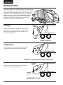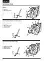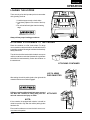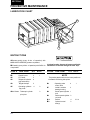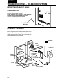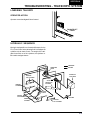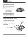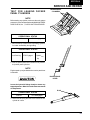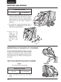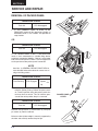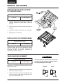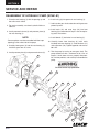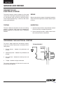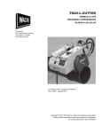
1
2RII PACKMASTER SERVICE MANUAL Over Serial Number 16000 BUILDING THE BEST WARRANTY Refuse bodies manufactured by Leach Company, (“Company”) are supplied and sold under a Limited Warranty that they are and will remain free of defects in workmanship or material for a period of six (6) months from the date of original sale under reasonable conditions of use and operation, providing required planned maintenance services are performed. Extended warranty packages are available for purchase. If a failure occurs during said period because of such defect in the opinion of the Company, the component or part shall be repaired or replaced by an authorized Leach Distributor at no cost to the customer provided the unit is brought to the distributor’s service facility. After three (3) months, performance of adjustments or the replacement of wear/expendable components is not covered under warranty. This limited warranty is the sole and exclusive warranty of the Leach Company. THE COMPANY MAKES NO WARRANTY AS TO MERCHANTABILITY, FITNESS FOR USE, LEGALITY OF OPERATION IN ANY JURISDICTION OR ANY IMPLIED WARRANTY OF ANY KIND OR NATURE. THE COMPANY SHALL NOT BE LIABLE FOR ANY SPECIAL OR CONSEQUENTIAL DAMAGES OF ANY KIND OR NATURE, OTHER THAN ITS LIMITED WARRANTY OF REPLACEMENT HEREIN. NO OTHER PERSON, FIRM, OR CORPORATION CAN BIND THE COMPANY TO ANY WARRANTY OTHER THAN HEREIN ABOVE STATED. To validate the new unit warranty, an authorized Leach Distributor must have completed a predelivery inspection before the unit is placed into service, and the delivery report form signed by both the customer and the distributor must be submitted to the Leach Service Department. Because Company products are engineered to work only with genuine Company parts, this limited warranty will be void and of no effect if: (a) Company products are modified other than as done at its factory or as authorized to be done by the factory in writing; or (b) Parts or assemblies of any other manufacturer are used as substitutes for genuine Company parts. Genuine Leach replacement parts, components and assemblies are also sold under a Limited Warranty to be free from defects in workmanship or material for a period of six (6) months. This is a replacement only warranty and the item must be returned to the Leach distributor for exchange. The labor to replace or repair the part shall be the responsibility of the customer. There is no warranty on expendable items, wear components or used parts. Leach Company reserves the right to redesign and/or discontinue the manufacture of parts, components and assemblies at any time. II FOREWARD Leach Company has been a leader in the refuse industry for over 110 years. Leach refuse bodies are the industry standard for both quality and performance. Leach Company is justifiably proud of the quality engineering, material and workmanship that goes into each and every packer we produce. This commitment to quality extends to the best parts, service and distributor organization in the industry. One area of great importance to us is your safety. This unit was built in accordance with the American National Standards Institute (ANSI) standard for Mobile Refuse Collection and Compaction Equipment-Safety Requirements, ANSI Z245.1-1992. Before operating this unit please read and understand the safety precautions found in Section 2 of this manual. They are important and are provided to assist you in the safe operation of the unit. This manual was produced with the intention of providing clear, concise instructions for the proper operation, maintenance and service of your 2RII refuse packer. It was produced with the latest information available at the time of publication. We do, however, reserve the right to redesign and/or discontinue the manufacture of parts, components or assemblies at any time. Leach Company has an aggressive manual and product improvement program. In any conversation or correspondence dealing with the information provided in any Leach manual please refer to the part number of that manual. The manuals provided with the unit are considered a permanent part of the unit and should be included in the event of a re-sale. Additional manuals are available, free of charge, from your local authorized Leach distributor. These manuals should be kept readily available for easy reference. We ask that if you have comments or suggestions concerning this manual, please contact us at (920) 231-2770. We are here to be of service to you, our valued customer. III TABLE OF CONTENTS WARRANTY . . . . . . . . . . . . . . . . . . . . . . . . . . . . II FOREWORD . . . . . . . . . . . . . . . . . . . . . . . . . . . III TABLE OF CONTENTS . . . . . . . . . . . . . . . . . . IV SECTION 1 – SAFETY PRECAUTIONS General . . . . . . . . . . . . . . . . . . . . . . . . . . . . . . . 1-1 Danger, Warning and Caution Decals . . . . . . . . . 1-1 Prior To Start Up . . . . . . . . . . . . . . . . . . . . . . . . 1-2 Operation . . . . . . . . . . . . . . . . . . . . . . . . . . . . . . 1-3 Hydraulics . . . . . . . . . . . . . . . . . . . . . . . . . . . . . 1-5 Fire Protection . . . . . . . . . . . . . . . . . . . . . . . . . . 1-5 Housekeeping . . . . . . . . . . . . . . . . . . . . . . . . . . 1-5 Shutdown. . . . . . . . . . . . . . . . . . . . . . . . . . . . . . 1-5 Decal Locations . . . . . . . . . . . . . . . . . . . . . . . . . 1-6 SECTION 3 – OPERATION (continued) Loading the Hopper . . . . . . . . . . . . . . . . . . . . . 3-13 Attaching a Container to the Packer . . . . . . . . . 3-13 Using a Winch or Container Lift Cylinder. . . . . . 3-14 Using a Container Push Bar . . . . . . . . . . . . . . . 3-15 Packing the Load . . . . . . . . . . . . . . . . . . . . . . . 3-15 Pushout Panel Operation During Packing Telescopic . . . . . . . . . . . . . . . . . . . . . . . . . 3-16 Disconnecting the Container. . . . . . . . . . . . . . . 3-16 Unloading at Dumpsite . . . . . . . . . . . . . . . . . . . 3-17 Lifting the Tailgate . . . . . . . . . . . . . . . . . . . . . . 3-17 Ejecting the Load . . . . . . . . . . . . . . . . . . . . . . . 3-18 Lowering the Tailgate . . . . . . . . . . . . . . . . . . . . 3-18 Shut Down . . . . . . . . . . . . . . . . . . . . . . . . . . . . 3-19 SECTION 4 – GENERAL REPAIR PRACTICES SECTION 2 – INTRODUCTION Terms You Will Need To Know. . . . . . . . . . . . . . . 2-1 Loading . . . . . . . . . . . . . . . . . . . . . . . . . . . . . . . 2-2 Compaction . . . . . . . . . . . . . . . . . . . . . . . . . . . . 2-2 Unloading. . . . . . . . . . . . . . . . . . . . . . . . . . . . . . 2-3 Container Attachment. . . . . . . . . . . . . . . . . . . . . 2-4 Container Handling Systems . . . . . . . . . . . . . . . 2-4 General . . . . . . . . . . . . . . . . . . . . . . . . . . . . . . . 2-5 Terms You Need to Know . . . . . . . . . . . . . . . . . . 2-5 Hook . . . . . . . . . . . . . . . . . . . . . . . . . . . . . . 2-5 Container . . . . . . . . . . . . . . . . . . . . . . . . . . . 2-5 Container Attachment. . . . . . . . . . . . . . . . . . 2-5 Winch . . . . . . . . . . . . . . . . . . . . . . . . . . . . . 2-6 Container Lifting Cylinder (CLC) . . . . . . . . . . 2-6 Container Push Bar . . . . . . . . . . . . . . . . . . . 2-6 Basic Operation . . . . . . . . . . . . . . . . . . . . . . . . . 2-7 Attach . . . . . . . . . . . . . . . . . . . . . . . . . . . . . 2-7 Dump. . . . . . . . . . . . . . . . . . . . . . . . . . . . . . 2-7 Disconnect . . . . . . . . . . . . . . . . . . . . . . . . . . 2-7 Preparation for Service. . . . . . . . . . . . . . . . . . . . 4-1 Replacement Parts. . . . . . . . . . . . . . . . . . . . . . . 4-1 Service Bulletins . . . . . . . . . . . . . . . . . . . . . . . . 4-1 Safety Precautions . . . . . . . . . . . . . . . . . . . . . . . 4-2 Prior to Performing Any Service or Repair . . 4-2 Safety During Service and Repair. . . . . . . . . . . . 4-2 Welding Precautions. . . . . . . . . . . . . . . . . . . . . . 4-2 Electric Welders . . . . . . . . . . . . . . . . . . . . . . 4-2 Oxy-Acetylene Torches. . . . . . . . . . . . . . . . . 4-3 Removal, Disassembly and Repair . . . . . . . . . . . 4-3 Reassembly and Installation . . . . . . . . . . . . . . . . 4-4 Electrical Testing . . . . . . . . . . . . . . . . . . . . . . . . 4-4 Checking for Voltage . . . . . . . . . . . . . . . . . . 4-4 Checking Continuity . . . . . . . . . . . . . . . . . . . 4-4 Welding . . . . . . . . . . . . . . . . . . . . . . . . . . . . . . . 4-4 Lifting Instructions . . . . . . . . . . . . . . . . . . . . . . . 4-5 Capacity of Lifting Device Required for Removal. . . . . . . . . . . . . . . . . . 4-5 Sling Strap Specifications . . . . . . . . . . . . . . . . . . 4-5 Chain and Hardware Specifications . . . . . . . . . . 4-5 Capscrew Marking and Torque Values . . . . . . . . 4-6 SECTION 3 – OPERATION General . . . . . . . . . . . . . . . . . . . . . . . . . . . . . . . 3-1 Description of Operating Controls . . . . . . . . . . . . 3-1 Location Of Operating Controls . . . . . . . . . . . . . 3-2 Compaction Cycle Operation . . . . . . . . . . . . . . . 3-5 Operating Procedures . . . . . . . . . . . . . . . . . . . . 3-6 Pre-operating Walk-around Inspection . . . . . . . . 3-6 Walk-around Inspection Checklist . . . . . . . . . . . 3-10 Start Up (Operating Instructions) . . . . . . . . . . . 3-11 Positioning Pushout Panel . . . . . . . . . . . . . . . . 3-12 SECTION 5 – SPECIFICATIONS Body Dimension Illustration . . . . . . . . . . . . . . . . 5-1 Lubricants . . . . . . . . . . . . . . . . . . . . . . . . . . . . . 5-2 Hydraulic System . . . . . . . . . . . . . . . . . . . . . . . . 5-2 Capacity . . . . . . . . . . . . . . . . . . . . . . . . . . . 5-2 Total System . . . . . . . . . . . . . . . . . . . . . . . . 5-2 Pump . . . . . . . . . . . . . . . . . . . . . . . . . . . . . . 5-2 Leach Hydraulic Fluid Recommendation . . . . . . . 5-2 Hydraulic Fluid . . . . . . . . . . . . . . . . . . . . . . . . . . 5-2 IV TABLE OF CONTENTS SECTION 6 – PREVENTIVE MAINTENANCE SECTION 8 – TROUBLESHOOTING (continued) General . . . . . . . . . . . . . . . . . . . . . . . . . . . . . . . 6-1 Operating and Maintenance Records . . . . . . . . . 6-1 Lubrication Chart . . . . . . . . . . . . . . . . . . . . . . . . 6-2 Hydraulic System Service. . . . . . . . . . . . . . . . . . 6-5 Checking Fluid Level (Daily) . . . . . . . . . . . . . 6-5 Clean Tank Breather (Weekly) . . . . . . . . . . . 6-5 Check/Replace Return Line Filter Element . . . . . . . . . . . . . . . . . . . . 6-5 Replacement of Filter Element . . . . . . . . . . . . . . 6-5 Cleaning Hydraulic Strainer (Monthly). . . . . . 6-5 Flushing Hydraulic System (Yearly) . . . . . . . 6-6 Hydraulic System Service. . . . . . . . . . . . . . . . . . 6-7 Contamination . . . . . . . . . . . . . . . . . . . . . . . 6-7 Commercial Hydraulic Fluid Testing . . . . . . . 6-7 In House Fluid Testing . . . . . . . . . . . . . . . . . 6-7 Preventive Maintenance Requirements . . . . . . . . 6-8 Daily Preventive Maintenance. . . . . . . . . . . . 6-8 Weekly Preventive Maintenance . . . . . . . . . . 6-9 Yearly Preventive Maintenance . . . . . . . . . . . . . 6-10 Packer Panel Valve Section Shifts too Soon . . . . 8-4 Carrier Panel Valve Section Shifts to Neutral too Soon . . . . . . . . . . . . . . . . . . . . . 8-5 Packer Panel Valve Section Will Not Shift . . . . . . 8-5 Carrier Panel Valve Section Will Not Shift To Neutral . . . . . . . . . . . . . . . . . . . . . . . . . . 8-5 Packer Panel Does Not Deliver Full Force to in House Hydraulic Fluid Testing. . . . . . . . 8-5 Loud Squealing Noise When Manually Retracting Telescopic Cylinder . . . . . . . . . . . 8-6 Load Will Not Push Out . . . . . . . . . . . . . . . . . . . 8-6 Pushout Panel Slides Forward Too Fast While Packing Refuse . . . . . . . . . . . . . . . . . 8-6 Pushout Panel Will Not Slide Forward Automatically . . . . . . . . . . . . . . . . . . . . . . . . 8-6 Carrier and Packer Panel Stop Short of Home Position After Each Cycle . . . . . . . . 8-6 Pushout Panel Returns When Pushout Cylinder is Retracted . . . . . . . . . . . . . . . . . . 8-7 Pushout Cylinder Will Not Extend to Push Out Load . . . . . . . . . . . . . . . . . . . . . . . . . . . 8-7 Load Will Not Push Out . . . . . . . . . . . . . . . . . . . 8-7 Packer Panel Drifts Open While Packing Load Into Body. . . . . . . . . . . . . . . . . . . . . . . 8-7 Cycle Time is Too Slow. . . . . . . . . . . . . . . . . . . . 8-7 Tailgate Will Not Raise . . . . . . . . . . . . . . . . . . . . 8-7 Container Won’t Lift . . . . . . . . . . . . . . . . . . . . . . 8-8 Winch Motor Leaking . . . . . . . . . . . . . . . . . . . . . 8-8 Container Raises Very Slowly . . . . . . . . . . . . . . . 8-8 Description of Hydraulic System . . . . . . . . . . . ... 8-9 Hydraulic system sequence (Neutral). . . . . . . . . .8-10 (Packer panel sweeps back over load). . 8-11 (Carrier and Packer panels move to interrupted cycle position). . . . . . . . . . . . 8-12 (Packer panel sweeps hopper). . . . . . . . 8-13 (Packing refuse). . . . . . . . . . . . . . . . . . . 8-14 (Raising tailgate). . . . . . . . . . . . . . . . . . .8-15 (Ejecting load). . . . . . . . . . . . . . . . . . . . 8-16 (Retracting Pushout panel). . . . . . . . . . . 8-17 (Lowering Tailgate). . . . . . . . . . . . . . . . . 8-18 SECTION 7 – CHECK-OUT General . . . . . . . . . . . . . . . . . . . . . . . . . . . . . . . 7-1 Check Hydraulic Tank Fluid Level . . . . . . . . . . . . 7-1 Check Engine Solenoid Switch . . . . . . . . . . . . . . 7-2 Check Engine Speed-Up Switches . . . . . . . . . . . 7-2 Check Packing Cycle Time . . . . . . . . . . . . . . . . . 7-3 Check Pressures . . . . . . . . . . . . . . . . . . . . . . . . 7-3 Check Main Line Pressure . . . . . . . . . . . . . . . . . 7-4 Check Packer and Carrier Panel Shifting Pressure . . . . . . . . . . . . . . . . 7-5 Check Resistance Cartridge Pressure . . . . . . . . 7-6 Check Pushout Shoes and Wear Blocks . . . . . . . 7-7 Power Take Off (PTO). . . . . . . . . . . . . . . . . . . . . 7-7 SECTION 8 – TROUBLESHOOTING SECTION 9 – SERVICE AND REPAIR General . . . . . . . . . . . . . . . . . . . . . . . . . . . . . . . 8-1 Compaction . . . . . . . . . . . . . . . . . . . . . . . . . . . . 8-1 Dieseling in Hydraulic Systems. . . . . . . . . . . . . . 8-2 Operation is Erratic. . . . . . . . . . . . . . . . . . . . . . . 8-3 Pump Noise is Excessive . . . . . . . . . . . . . . . . . . 8-3 Engine Will Not Speed-Up When Carrier Panel Lever or Speed -UP Button is Engaged . . . . 8-4 Engine Speed Will Not Return to Normal When Packing Cycle is Completed or Speed-Up Button is Released . . . . . . . . . . . 8-4 General . . . . . . . . . . . . . . . . . . . . . . . . . . . . . . . 9-1 Description of Operating Cylinders . . . . . . . . . . . 9-1 Test for Leaking Packer Panel Cylinders . . . . . . . 9-2 Test for Leaking Carrier Panel Cylinders . . . . . . . 9-4 Removal of Packer Panel Cylinders . . . . . . . . . . 9-7 Removal of Carrier Panel Cylinders . . . . . . . . . . 9-9 Disassembly of Operating Cylinders . . . . . . . . . 9-11 Inspection and Replacement of Operating Cylinders . . . . . . . . . . . . . . . . . . 9-11 V TABLE OF CONTENTS SECTION 9 – SERVICE AND REPAIR (continued) Reassembly and Installation of Operating Cylinders . . . . . . . . . . . . . . . . . . 9-12 Description of the Packer Panel . . . . . . . . . . . . 9-12 Bearing Replacement . . . . . . . . . . . . . . . . . . . . 9-12 Roller Replacement/Shimming . . . . . . . . . . . . . 9-13 Description of Tailgate Lift Cylinders . . . . . . . . . 9-15 Test for Leaking Tailgate Cylinder . . . . . . . . . . . 9-15 Removal of Tailgate Lift Cylinders . . . . . . . . . . . 9-16 Disassembly of Tailgate Lift Cylinder . . . . . . . . . 9-17 Inspection and Replacement of Tailgate Lift Cylinder . . . . . . . . . . . . . . . . . . 9-17 Reassembly and Installation of Tailgate Lift Cylinder . . . . . . . . . . . . . . . . . . . . . . . . 9-17 Description of Tailgate Assembly . . . . . . . . . . . 9-18 Removal of the Tailgate Assembly . . . . . . . . . . 9-18 Inspection of Tailgate . . . . . . . . . . . . . . . . . . . . 9-19 Reassembly and Installation of Tailgate. . . . . . . 9-19 Front Control Valve . . . . . . . . . . . . . . . . . . . . . . 9-20 Removal of Front Control Valve. . . . . . . . . . . . . 9-20 Disassembly and Inspection of Front Control Valve. . . . . . . . . . . . . . 9-20 Reassembly of Front Control Valve. . . . . . . . . . 9-21 Reinstallation of Front Control Valve. . . . . . . . . 9-22 Main Control Valve (MCV) General. . . . . . . . . . 9-23 Removal of the Main Control Valve . . . . . . . . . . 9-24 Disassembly and Inspection of the Main Control Valve . . . . . . . . . . . . . . . . . . . 9-25 Reassembly of Main Control Valve . . . . . . . . . . 9-25 Disassembly and Inspection of the Knockout Positioner . . . . . . . . . . . . . . . . . . 9-26 Reassembly of Knockout Positioner . . . . . . . . . 9-26 Removal of Telescopic Pushout Cylinder. . . . . . 9-27 Telescopic Cylinder Packing Replacement . . . . 9-28 Telescopic Cylinder Disassembly . . . . . . . . . . . 9-29 Description of Pushout Panel . . . . . . . . . . . . . . 9-30 Front Wear Block Replacement. . . . . . . . . . . . . 9-30 Rear Wear Block Replacement Telescopic System . . . . . . . . . . . . . . . . . . . 9-31 Shimming Upper Wear Blocks with Panel in Place. . . . . . . . . . . . . . . . . . . 9-31 Removal of Pushout Panel . . . . . . . . . . . . . . . . 9-32 Installation of Pushout Panel . . . . . . . . . . . . . . 9-33 Description of Carrier and Packer Panels . . . . . 9-34 Removal of Packer Panel . . . . . . . . . . . . . . . . . 9-35 Inspection and Replacement of Packer Panel . . 9-36 SECTION 9 – SERVICE AND REPAIR (continued) Installation of Carrier Panel. . . . . . . . . . . . . . . . 9-39 Track Bar Replacement . . . . . . . . . . . . . . . . . . 9-39 Description of Leach Hydraulic Pump . . . . . . . . 9-40 Removal of Hydraulic Pump . . . . . . . . . . . . . . . 9-40 Installation of Hydraulic Pump. . . . . . . . . . . . . . 9-41 New Pump Preparation . . . . . . . . . . . . . . . . . . 9-41 Disassembly of Hydraulic Pump . . . . . . . . . . . . 9-42 Replacing Shaft Seals on the Hydraulic Pump . 9-42 Reassembly of 307451-01 Hydraulic Pump. . . . 9-43 Description of Electrical System . . . . . . . . . . . 9-44 Testing . . . . . . . . . . . . . . . . . . . . . . . . . . . 9-44 Repair . . . . . . . . . . . . . . . . . . . . . . . . . . . . 9-44 Inspection . . . . . . . . . . . . . . . . . . . . . . . . . 9-44 Grounding the Electrical System. . . . . . . . . . . . 9-44 Replacement of Packer Edge . . . . . . . . . . . . . . 9-37 Installation of Packer Panel. . . . . . . . . . . . . . . . 9-37 Carrier Panel . . . . . . . . . . . . . . . . . . . . . . . . . . 9-38 Removal of Carrier Panel . . . . . . . . . . . . . . . . . 9-38 Inspection and Replacement of Carrier Panel . . 9-39 VI SECTION 1 SAFETY PRECAUTIONS GENERAL The 2RII Packmaster has been designed with the operator in mind. However, as with any industrial machinery, especially those that are large and apply forces through hydraulic pressures, the ultimate responsibility for safety rests with you — the user. An alert, conscientious attitude and observance of all known safe operating practices are the best ways to prevent accidents. Publication of these precautions does not imply or in any way represent an all inclusive list. It is the operator’s responsibility to be familiar with and ensure that operation is in accordance with safety requirements and codes including all applicable Occupational Safety & Health Act (OSHA) and American National Standards Institute (ANSI) regulations. Before operating the unit it is the operator’s responsibility to be thoroughly familiar with the instructions contained in the Operator’s Manual. DANGER, WARNING AND CAUTION DECALS See the accompanying illustration for the location and label content of all safety decals. 1. These decals must be obeyed at all times. 2. These decals must be in place at all times. Report any damaged or missing decals to the proper authority at once. 3. Replacement decals can be ordered free of charge from your local authorized Leach distributor. DANGER WARNING AND CAUTION Throughout this manual “DANGER” “WARNING” and “CAUTION” notations accompanied by the International Hazard Symbol are used to alert the operator and mechanics to special instructions concerning a particular operation or service that may be hazardous if performed incorrectly or carelessly. DANGER — Immediate hazards which WILL result in severe personal injury or death. WARNING — Hazards or unsafe practices which COULD result in severe personal injury or death. CAUTION — Hazards or unsafe practices which could result in minor personal injury or property or product damage. Strict compliance to these “safety alerts” combined with “common sense” operations are important accident prevention measures. The word NOTE is also used throughout the manual. It precedes information that provides special emphasis or clarification on a specific operation or procedure. 1-1 SECTION 1 SAFETY PRECAUTIONS PRIOR TO START UP 1. Never operate machinery while wearing jewelry or loose clothing. These items may become caught by or entangled in the machinery causing serious injury. Wear proper safety equipment as required by your employer. 2. Never operate machinery while under the influence of alcohol, narcotics or other mood altering substances. Workers who operate machinery while under the influence are a hazard to themselves and others. 3. Perform a pre-operation “walk around” inspection of the truck chassis in accordance with the chassis manufacturer’s guidelines. Perform a “walk around” inspection of the refuse packer in accordance with the checks listed in Section 3 - Operation of the Operators/Service manual. Never start or operate any equipment found to have malfunctions. a. Report any malfunctions immediately to the proper authorities. b. Prior to leaving any malfunctioning unit the parking brakes must be set, the PTO system disengaged, the engine turned off, the ignition key removed, and using a non-reusable fastening device, place a sign on the steering wheel indicating the unit is inoperative. 4. Proper servicing requires specialized tools and procedures. Service must be performed by authorized personnel only following procedures in the 2RII Service manual. 5. Walk completely around the vehicle to make sure all persons and obstructions are clear before starting the unit. 6. The container handling system is a critical component of the unit, use only the proper replacement parts. 7. Inspect all hooks, chains and cables daily to ensure serviceable condition. Replace damaged or worn parts. (See Section 5, Preventive Maintenance) 8. Before operating the vehicle the driver must be thoroughly familiar with the employer’s safety program concerning traffic rules, warning devices and hand signals. 9. Be sure to know where to get assistance in the event of an emergency. 10. Know your machine. Know the location and function of all controls, gauges, instruments and protective devices. 11. Should the height of a refuse collection vehicle be altered by installing a container handling system, be sure the overall height is rechecked and overall height plus 3 inches is noted on the decals. 1-2 SECTION 1 SAFETY PRECAUTIONS OPERATION GENERAL 1. It is the operator’s responsibility to ensure that operation of the unit is in accordance with the guidelines contained in the Operator’s manual and in accordance with all applicable codes including Occupational Safety and Health Act (OSHA) and American National Standards Institute (ANSI) regulations. vest, protective glasses and protective shoes. 17. All service opening covers and access doors must be maintained and latched in place while operating equipment. 18. Ensure all co-workers are in view before operating or moving any controls or the unit. 19. Ensure that there is sufficient overhead clearance before operating the unit. 3. Move the vehicle as slowly as possible without stalling when traveling in reverse. 20. Ride only in the cab or on riding platforms designed for that purpose. Riding steps shall not be used when speeds are expected to exceed 10 mph or when distance traveled without stopping will exceed 2⁄10 of one mile. Do not mount or dismount riding step when vehicle is in motion. 4. Always make sure the area behind the unit is clear before traveling in reverse. 21. Never allow anyone to ride on the steps when the vehicle is backing up. 5. Do not travel in reverse for distances greater than those dictated by local ordinances. If reverse travel exceeds 10 feet, use a “spotter” or move the vehicle in 10 foot increments only, and then check to make sure the area behind the unit is clear between increments. 22. Stop the vehicle immediately if warning lights for the TAILGATE AJAR system come on. 2. Do not attempt to operate this equipment without proper training. 6. Do not attempt to dislodge any material above waist level unless wearing eye protection such as “approved” side shielded safety glasses or a full face shield. 7. Never use the unit to push or tow another vehicle. 8. Never unload uphill or against a pile of refuse or into the bank of a hill. 9. Never place head, body, fingers or any limbs into a scissors point or pinch point on the equipment. 10. Before operating the vehicle the driver must be thoroughly familiar with the employer’s safety program concerning traffic rules, warning devices and hand signals. 11. Know where to get assistance in the event of an emergency. 12. Know your machine. Know the location and function of all controls, gauges, instruments and protective devices. 13. Wear your seat belt. 14. Start the engine following the manufacturer’s recommended procedure. 15. Always set the parking brake before leaving the cab. 16. Turn on appropriate warning lights, put on a safety 1-3 23. Never use controls or hoses for hand holds when mounting or dismounting. Controls and hoses are movable. They do not provide proper support and may cause accidental equipment movement. 24. Make sure the backup alarm is working properly. 25. Always ensure that all persons are clear before raising or lowering the tailgate. It is the operator's responsibility to warn all persons not to stand or cross under a raised tailgate. 26. Do not move the vehicle with the tailgate raised except during unloading and then only as necessary to clear the load before lowering. 27. Stand clear when the tailgate is being raised or lowered and during the unloading cycle. If it is necessary to manually clear debris from the hopper, use a long metal probe and DO NOT stand under the tailgate. 28. Never load the hopper above the loading sill. 29. Never allow material to extend outside of the hopper when packing. 30. Allow the packer panel control lever and carrier panel control lever to shift automatically. 31. To avoid possible bodily injury or equipment damage, lower the tailgate slowly. 32. Never enter the body unless the pushout panel clamp or the telescopic ejection system cylinder is released, PTO disengaged and ignition key removed and placed in your pocket. 33. Do not attempt to load refuse into the hopper after SECTION 1 SAFETY PRECAUTIONS the packing cycle has begun. The packer panel must be in the “home” position and stopped before loading the hopper. 34. The dashboard solenoid switch must be “OFF” between pickups or when parked. This prevents inadvertent engine speed-up if the tailgate carrier panel control lever is shifted. 35. The tailgate clamps must be tightened securely before starting to load. 36. Do not step on the throttle pedal while the speed up system is engaged. 37. Vehicles with automatic transmissions require the shift lever to be in gear to engage the PTO and then shifted to neutral to activate the PTO/pump. 38. Never use a rear loader to transport a container. 39. Follow all safety directions listed in the refuse body Operator and Service manual under SAFETY PRECAUTIONS. . 40. Never use container handling chains or cable for towing or pulling. 41. When not handling containers, keep the container attachment closed and latched. 42. Do not operate the rear loader’s packing mechanism with a container off the ground. 43. If it is necessary to manually free debris from the container, use a long metal probe while the container is on the ground, and DO NOT place yourself between the container and the packer body. 52. Raise the container with a smooth even movement. Do not bounce the container. 53. Do not slam the container against the packer tailgate or bump bar. 54. Do not attach the hook to any lift point which will not be completely encircled by the hook with the safety latch closed. Do not remove the hook safety latch. 55. Read and obey all container decals issued by the container manufacturer. 56. Read and follow container manufacturers information on accepted use practices. 57. Do not attempt to lift overloaded containers. 58. Center the container on the attachment. 59. All containers should be inspected for serviceability and repaired if not in a safe, usable condition. 60. Do not use a non-standard or damaged trunnion bar. 61. Never cross under a raised container. 62. Stand clear when dumping containers. 63. Before attempting to lift a container, below 32°F (0°C) make sure it is not frozen to the ground. 64. When using an eye type container attachment point, the base of the hook must be positioned to lift on the inside of the eye. 65. Place the container on a flat, level surface. 44. Attach hook to the tailgate and take up the excess slack when not in use. 54. Never hold the hook on an attachment point while taking up slack. 46. Take up excess cable slack before moving the vehicle. 47. Check overhead clearance before dumping a container. 48. Do not move the vehicle with a container attached. 49. Always set the vehicle parking brake before attaching or lifting a container. 50. Never lift a container which is non-compatible with the Leach container attachment. 51. Never lift a container without first latching both container latch arms. 1-4 SECTION 1 SAFETY PRECAUTIONS HYDRAULICS 1. Hydraulic fluid operates under high temperatures. Avoid contact with piping, hoses or cylinders to prevent burns. 2. Never use hands to check for leaks. Hydraulic fluid escaping under pressure may cause injury. 3. In case of injury seek proper medical treatment immediately. FIRE PROTECTION 1. Keep a fire extinguisher accessible at all times, as recommended by the Bureau of Motor Carrier Safety. 2. Never use lighted smoking materials, open flame or sparks around when working with flammable materials such as fuel tanks or storage batteries. 3. Never have an open flame as a light source. 4. Never load ashes or other materials which might be smoldering. These materials could ignite refuse in the packer body. HOUSEKEEPING Good housekeeping habits are a major factor in accident prevention. 3. Rubbish, scrap paper and litter are highly combustible. Such material should be stored in metal containers entirely clear of sparks and flames. 1. Keep handrails and steps clean and free of grease or debris. 2. Do not store brooms or other equipment where they could inadvertently activate the packer controls. SHUTDOWN 1. Put all controls in neutral. 2. Set parking brake. 3. Disengage PTO. 4. Shut off engine. 5. Shut off solenoid dashboard switch. 6. Remove key. 7. Lock vehicle. 1-5 1-5 SECTION 1 SAFETY PRECAUTIONS 1 3 1 7 9 8 7 4 5 2 1 2 6 10 4 3 5 7 6 10 8 1-6 9 1-6 SECTION 1 SAFETY PRECAUTIONS 3 4 5 1 2 3 1 1-7 2 4 5 SECTION 1 SAFETY PRECAUTIONS 4 7 9 10 13 15 16 18 19 8 20 21 22 14 23 6 11 2 3 1 17 1 12 5 2 3 4 5 7 6 8 9 10 1-8 SECTION 1 SAFETY PRECAUTIONS 14 13 12 11 15 18 16 17 19 20 21 23 1-9 22 SECTION 1 SAFETY PRECAUTIONS 12 44 6 44 20 30 43 7 28 5 8 15 4 16 39 21 34 4 6 5 7 12 8 16 15 43 20 44 21 28 39 30 1-10 SECTION 1 SAFETY PRECAUTIONS 1-11 SECTION 2 INTRODUCTION TERMS YOU WILL NEED TO KNOW TAILGATE ASSEMBLY HOPPER LOADING EDGE PUSHOUT PANEL HYDRAULIC TANK CARRIER PANEL PACKER PANEL 2-1 SECTION 2 INTRODUCTION The main purpose of the 2RII Packmaster is to safely and efficiently: load, compact, transport and unload refuse. The following describes how the unit performs those tasks in the most basic terms. For a more detailed description of the unit and its components, read the complete 2RII PACKMASTER SERVICE MANUAL. Before going further, look at the accompanying full page illustration of the 2RII Packmaster and become familiar with the terms you will need to know. CARRIER PANEL LOADING Refuse is first loaded into the hopper of the tailgate assembly. The carrier and packer panels, which sweep up and pack the refuse from the hopper, will be in the “home” position. PACKER PANEL "HOME" POSITION COMPACTION When the operator starts the packing cycle the carrier and packer panels move rearward, over the load. CARRIER & PACKER PANELS MOVE OVER LOAD Next, the carrier and packer panel automatically stop at the “interrupted cycle” position. CARRIER PANEL PACKER PANEL “INTERRUPTED CYCLE” 2-2 SECTION 2 INTRODUCTION PACKER The operator again activates the packing cycle. The PANEL carrier and packer panels move forward and sweep the refuse from the hopper up into the body and pack it against the pushout panel. Having completed a cycle, the carrier and packer panels are back into the “home” position and the hopper is cleared for more refuse. PUSHOUT PANEL CARRIER PANEL COMPACTION POSITION Also, during the compaction cycle, considerable hydraulic pressure is applied to the cylinders which control movement of the carrier and packer panels. This causes the refuse to be compacted tightly allowing for a large carrying capacity. CARRIER PANEL PUSHOUT PANEL On units with the standard clamp pushout system, the operator must manually release the pushout panel clamping system to allow movement of the pushout PACKER panel. PANEL Once the body is full the 2RII Packmaster can be PUSHOUT PANEL MOVES FORWARD moved to the dumpsite for unloading. UNLOADING At the dumpsite the unit is unloaded in two easy steps: First, the tailgate is raised by the operator. Second, the pushout panel is moved to the rear of the body, pushing out the load. TAILGATE After unloading, on telescopic units the tailgate is lowered and “latched” to the body. TAILGATE RAISED On clamp style units, the the pushout cylinder is retracted and then the clamp is set by extending the cylinder a couple of inches. The tailgate is then lowered and “latched” to the body. TAILGATE PUSHOUT PANEL PUSHOUT PANEL MOVES REARWARD EJECTING THE LOAD 2-3 SECTION 2 INTRODUCTION CONTAINER ATTACHMENT The Leach Container Attachment system consists of a loading edge with a latch assembly and a guide ear (ear) on each side of the packer tailgate. The latches and ears are installed to accomodate containers from one (1) to ten (10) cubic yard capacity. The standard container for use with the Leach rear loader must have an ANSI Standard 11/4" - 13/4" diameter trunnion bar which is between 771/2"and 78" end to end. This trunnion bar length will center the container between the “ears” and prevent the container from moving sideways. The latch arms must be manually raised and secured by the arm latch. The container arms, when properly latched together with the guide ears, will secure the container to the packer. ARM LATCH Only containers that meet the American National Standards Institue (ANSI) regulations should be used in conjuction with Leach Container Handling Systems. ARMS CONTAINER HANDLING SYSTEMS To lift or dump a container, several systems are available. A hydraulically operated container push bar is available to handle containers of 1 to 3 cubic yard capacity. PUSH BAR The handling of containers with capacities of four (4) or more cubic yards requires the use of a drum winch or roof mounted container lifting cylinder. Drum winches are rated at various pounds of pull. Leach Company offers winches with 8,000, 12,000 and heavy duty 12,000 lb. ratings. The Leach container lift cylinder is rated at 12,000 pounds. NO TE: Leach bodies are capab le of being equipped with more than one container handling system. LIFTING CYLINDER 2-4 DRUM WINCH SECTION 2 INTRODUCTION GENERAL TERMS YOU NEED TO KNOW The main purpose of a refuse body is to load, compact, transport and unload refuse. To assist in loading of refuse in containers, various container handling systems are available to be mounted on Leach rear loaders. Before going further, become familiar with the container handling terms you will need to know. A refuse container may be a mobile residential one (1) cubic yard container with casters or a ten (10) cubic yard stationary commercial container. The equipment required to lift and empty these containers will vary according to the container’s type and size. HOOK 1 4 1. Throat Opening 2. Back 3. Heel 4. Hook Safety Latch 5. Point 6. Base 5 2 6 3 CONTAINER 3 2 1. Trunnion bar 2. Hook point 3. Lid 1 3 CONTAINER ATTACHMENT 2 4 1. Loading sill 2. Arm 3. Latch 4. Guide ear 1 2-5 SECTION 2 INTRODUCTION 4 WINCH 3 1. Control lever 2. Engine speed up button 3. Cable 4. Winch assembly 5. Container attachment 6. Stop bar/Lid guard 6 1 2 5 5 CONTAINER LIFTING CYLINDER (CLC) 4 1. Control lever 2. Engine speed-up button 3. Roller guide 4. Cable 5. Lifting cylinder assembly 6. Container attachment 7. Stop bar/Lid guard 3 7 6 1 2 CONTAINER PUSH BAR (CPB) 1. Control lever 2. Push bar 3. Lift roller 4. Container dumping cylinder 5. Stop bar/ Lid guard 6. Container attachment 5 6 1 3 2-6 2 4 SECTION 2 INTRODUCTION BASIC OPERATION All Leach container handling systems have three (3) basic steps for operation. ATTACH The first step in container handling is to attach the container to the rear loader by securing it with the latch arms of the container attachment. ATTACH CONTAINER DUMP A container handling system is used to raise the container and empty the refuse into the hopper of the rear loader. DUMP DISCONNECT When the container is empty, it is lowered to the ground, the latch arms released and the truck is moved forward. DISCONNECT 2-7 SECTION 3 OPERATION GENERAL This section will provide all of the instructions necessary to operate the 2RII Packmaster. However, prior to attemting any operation of the unit, make sure you are familiar with all of the safety information contained in Section 1, SAFETY PRECAUTIONS. DESCRIPTION OF OPERATING CONTROLS The following information is for descriptive purposes only. It is not to be misconstrued as operating instructions. For operating instructions, refer to OPERATING PROCEDURES later in this section. There are only a few controls required for the complete and efficient operation of the 2RII Packmaster. It is important that you know the location and function of each control before attempting to operate the unit. Refer to the accompanying illustrations for their location. 3-1 SECTION 3 OPERATION LOCATION OF OPERATING CONTROLS 1 8 9 10 11 12 2 3 7 8 7 4 5 6 3-2 SECTION 3 OPERATION PUMP/PTO CONTROL (1) The Pump/PTO (Power Take-Off) is engaged to put the hydraulics in operation. The exact location of the Pump/ PTO control will vary depending on the type, truck chassis style and control panel location. The Pump/PTO may be engaged by use of a lever, rocker switch, push-pull cable, toggle lever or positive control button depending on the style. Be sure to read all safety decals associated with the Pump/PTO before attempting operation. SOLENOID ON-OFF SWITCH (2) This switch energizes the engine speed-up system. It is located on the cab control panel (exact location dependent on cab make and style). NOTE: The engine speed-up system consists of the solenoid ON-OFF switch, a relay and solenoid air cylinder (on electronic engines, the relay is wired to the engine ECU). A speed-up push button and speed-up switch connected to the operating control linkage on the Operating Valve. The function of the speed-up system is to speed-up the engine and provide more power to the hydraulic pump during operation of the various hydraulic cylinders. TAILGATE OPEN LIGHT (3) This warning light, located in the cab, will illuminate if the tailgate is ajar. Having the tailgate ajar will also sound the backup alarm and illuminate the backup lights. G WARNIN ATE TAILG OPEN Operation of the unit with an illuminated or defective warning system can result in personal injury and / or equipment damage. 3-3 WARNIN E TAILGAT OPEN G SECTION 3 OPERATION ENGINE SPEED-UP PUSH BUTTON (4) When depressed, this push button switch will cause the engine to speed-up and supply more power to the hydraulic system. Located on the lower front left side of the body, it is depressed by the operator when operating either the pushout lever or tailgate lift lever. PUSHOUT LEVER NOTE Additional speed-up control buttons may be installed with optional winches and container attachments. FRONT CONTROL VALVE FRONT CONTROL VALVE TAILGATE LIFT LEVER The front control valve is located behind the access door on the front left hand side of the body. The control levers for this valve extend out through a cutout in the door. This valve controls the ejection (pushout) panel and the lifting of the tailgate. PUSHOUT LEVER (5) The upper lever controls the movement of the pushout panel. Moving the control lever rearward (toward the tailgate) will move the pushout panel to the rear. Moving the control lever forward (toward the cab) will move the pushout panel to the front. ENGINE SPEED UP BUTTON TAILGATE LIFT LEVER (6) The lower lever controls the tailgate. Moving the lever rearward (toward the tailgate) will raise the tailgate. Moving the lever forward (toward the cab) will lower the tailgate. TAILGATE CLAMPS (7) Tailgate clamps are located on each side of the tailgate at the bottom where the tailgate rests against the body. They are used to secure the tailgate to the body during operation. They must be manually loosened and swung away from the body before raising the tailgate. Before attempting to loosen the tailgate clamps, pressure against the tailgate must be relieved by opening the packer panel to the interrupted cycle stop position. TAILGATE CLAMPS 3-4 SECTION 3 OPERATION DRIVER SIGNAL PUSH BUTTONS (8) These two push buttons, one located on each side of the tailgate, are connected to a buzzer mounted under the drivers seat or under the dash in the chassis cab. The operator depresses one of these push buttons to signal the driver when the loading operation is completed and the truck is ready to be moved. DRIVER SIGNAL PUSH BUTTONS PACKER AND CARRIER PANEL OPERATIONAL LEVERS (9) (10) A. Packer panel lever (9) The packer panel operational control lever is located on the right (curb) side of the tailgate. It is used by the operator to position the packer panel open or closed during the compaction cycle operation. NOTE The engine speed up system does not engage if only the packer panel lever is shifted. The carrier panel lever must also be shifted to engage the engine speed up system. B. Carrier panel lever (10) The carrier panel operational control lever is located on the right (curb) side of the tailgate. It is used by the operator to position the carrier panel up or down during the compaction cycle. NOTE The engine speed up system automatically engages any time the carrier panel lever is shifted. CARRIER PANEL LEVER PACKER PANEL LEVER COMPACTION CYCLE OPERATION Both the packer panel lever and the carrier panel lever are shifted simultaneously inward to open the packer panel and lower the carrier panel to the interrupted cycle position. Both levers are shifted outward to sweep the load from the hopper and pack it against the pushout panel. Any time the carrier panel lever is shifted, the engine speed up automatically engages. The packing cycle may be stopped at any point by moving both operating levers to neutral. The packer or carrier panel can be moved independently. CONTAINER HANDLING CONTROL LEVERS (11) (12) These control levers are provided when container handling attachments (drum winch, reeving cylinder or container push bar) are added to the unit. They are used to raise and lower the container causing the refuse to be deposited in the hopper for compaction. The levers are located on the right (curb) side of the tailgate directly above the packer and carrier panel control levers. A refuse vehicle may have none, one or two control levers, depending on the configuration of the unit. 3-5 CONTAINER HANDLING CONTROL LEVERS SECTION 3 OPERATION OPERATING PROCEDURES This section of the manual provides all the instructions necessary to start and operate the 2RII Packmaster, including specific instructions for loading, packing and unloading the unit. NOTE It is important that operators and mechanics understand these procedures. PRE-OPERATING WALK-AROUND INSPECTION Each day, before starting the unit, perform the following walk-around inspection. 1. Refer to the decal location illustration in Section 1, SAFETY, of this manual and make sure all decals are in place and readable. Replace any decals that are not. NOTE A decal kit, free of charge, is available from your local authorized Leach distributor. 2. As you are checking for decals, also look for fluid leaks on and around the unit. Check for fluid leaks at the hydraulic cylinders, valves and fittings. 3. Inspect the mounting sills and attaching hardware. Make sure everything is tight and that there are no broken or excessively worn parts. Check capscrews and fasteners for looseness, visible welds for cracks and control levers for each movement. SPRINGS 3-6 SECTION 3 OPERATION 4. Make sure the tailgate clamps are in the closed position and securely tightened. 5. Check the hydraulic tank gauge to make sure the fluid is in the safe range. Add fluid, if necessary. (See Sec. 5, SPECIFICATIONS for the correct type of fluid to use.) The pushout cylinder must be retracted, the tailgate down, the carrier and packer panels in the interrupted cycle position to check the hydraulic fluid level. 1 1/2" TAILGATE CLAMPS 6. Make sure all operating levers are in the neutral position. Check: a. packer panel lever; b. Carrier panel lever; c. Pushout lever; d. Tailgate lift lever. PUSHOUT LEVER FRONT CONTROL VALVE Never operate the 2RII Packmaster with any part of the control system or levers removed or serious damage will result. Never under any circumstances enter the body if the truck is running. Open the packer panel and release the pushout panel clamp before entering the body. Always make sure the truck engine is off and the keys are in your pocket before entering the body. TAILGATE LIFT LEVER ENGINE SPEED UP BUTTON CARRIER PANEL LEVER PACKER PANEL LEVER 3-7 SECTION 3 OPERATION 7. Start the truck according to the manufacturers instructions and while it is warming up, continue the walk-around inspection. 8. Check all of the operating and running lights. Make sure none are missing and that there are no burned out bulbs. The tailgate open warning light should be off. Do not operate the unit if the light is illuminated. Never place hands in or near the packer panel during operation. 9. With the engine running, the speed-up solenoid switch ON, the PTO engaged and the transmission in neutral and the brakes applied, depress the speed-up push-button on the forward left (street) side of the body. You should hear the engine speed-up. Never hold the packer or the carrier panel lever in position by hand. Always engage and let go immediately. The only exception is at the end of a load. PUSHOUT LEVER FRONT CONTROL VALVE TAILGATE LIFT LEVER ENGINE SPEED UP BUTTON 3-8 SECTION 3 OPERATION 10. Move both the packer panel lever and carrier panel lever inward and let go. Check for the following: a. Engaging the carrier panel lever will activate an engine speed up switch, you should hear the engine speed up. b. Observe the carrier and packer panel move ment, it should be smooth. The panels should stop automatically at the interrupted cycle position. CARRIER PANEL LEVER PACKER PANEL LEVER 11. Move both the packer panel lever and carrier panel lever outward and let go. Observe the carrier and packer panel movement, it should be smooth. The panels should stop automatically at the home position. 12. Depress the two driver signal push buttons located on both sides of the tialgate to make sure that the audible alarm located in the cab is working. DRIVER SIGNAL PUSH BUTTONS (BOTH SIDES OF TAILGATE) 13. Back the unit up a few feet to ensure that the backup alarm is working properly. 14. Loosen the tailgate clamps and swing out. Raise the tailgate approximately 6 and check to see if the tailgate ajar light on the dash is on and if the backup alarm is audible. (Do not have the unit in reverse.) 3-9 TAILGATE CLAMPS SECTION 3 OPERATION Do not operate a unit that is in need of service or repair. 15. Report any problems found during the pre-operation walk-around inspection to the maintenance supervisor for service or repair, place a tag on the steering wheel, using a non-reusable fastener, stating the unit is inoperative and remove the keys. WALK-AROUND INSPECTION CHECKLIST 1. Decals in place and readable. 2. Look for any fluid leaks. 3. Mounting hardware tight and in place. 4. Tailgate clamps closed and tightened. 5. Hydraulic fluid reservoir at correct level. 6. All operating levers in neutral positions. 7. Pushout panel area clear of debris. 8. Engine warmed up according to manufacturer’s instructions. 9. All operating and running lights functioning. 10. Engine speed-up buttons operational. 11. Packing cycle operates properly. 12. Driver signal alarm can be heard. 13. Back-up alarm and tailgate ajar light are operable. 14. Report any problems to proper personnel. 3-10 SECTION 3 OPERATION START UP (OPERATING INSTRUCTIONS) 1. Inspect and start the truck as described in the preoperational walk-around inspection. 2. Engage the Pump/PTO control (to start the hydraulic pump). 3. Place the engine speed up switch in the ON position. ENGINE SPEED-UP SYSTEM ON 3-11 OFF SECTION 3 OPERATION POSITIONING PUSHOUT PANEL To load the unit, the pushout panel must be positioned toward the rear of the body. 1. Check the tailgate clamps to make sure both are securely tightened. TAILGATE CLAMPS 2. Depress and hold the speed-up push button. SPEED-UP BUTTON 3. Push the pushout lever rearward until the pushout cylinder is fully extended. NOTE On units with a telescopic pushout cylinder the pushout panel is now in position for loading. PUSHOUT LEVER 4. Release the speed-up button and pull the pushout lever forward until the pushout cylinder is fully retracted. 5. Repeat steps 2, 3 and 4 until the pushout panel is as far back as it will go and then pull forward on the pushout lever to fully retract the pushout cylinder. Now extend the cylinder a few inches to reset the clamp. SPEED-UP BUTTON 3-12 SECTION 3 OPERATION LOADING THE HOPPER There are only a few but important points to remember during loading of refuse. 1. Load the hopper evenly on both sides. 2. Load heavy objects in the center of the hopper. 3. Do not load refuse higher than the loading edge. Always follow proper loading procedures. ATTACHING A CONTAINER TO THE PACKER Place the container on a flat, level surface. For large non-moveable containers the driver should back the unit toward the container following all vehicle and refuse body safety restrictions. The vehicle should be backed with the latch arms open until the container trunnion bar is between the guide ears and within the latch assembly. Center the container on the attachment. ATTACHING CONTAINER LATCH ARMS DISCONNECTED After setting the vehicle parking brake, the right and left container latch arms must be engaged. Lifting a container without both latch arms secured can allow the container to swing away from the unit and cause severe injury or death. NOTE: If the container is equipped with wheels, it should be rolled into position only after the vehicle parking brake has been set. Even small containers must use the latch arms to secure them to the packer 3-13 ATTACHED SECTION 3 OPERATION USING A WINCH OR CONTAINER LIFT CYLINDER ATTACH CONTAINER Once the container is secured within the latch assembly, the lifting cable should be attached. Place the load in the base of the hook with the safety latch closing the throat opening. It is important that hooks are used in a proper manner. Proper use of a lifting hook not only includes placing the load in the base of the hook, but also includes ensuring that the hook is lifting on the proper area of the attachment point. The hook must completely encircle the attachment point. Equally as important, at the time load is applied to the base of the hook, the positioning must be correct to prevent the hook from dislodging. When using an eye type attachment point the base of the hook must be positioned to lift on the inside of the eye. The diagrams show both correct and incorrect positioning of the hook. LOWER TO CHECK CONTENTS INCORRECT CORRECT HOOK For the safety of yourself as well as others always ensure that a hook is positioned properly as slack is removed from the chain/cable before lifting. ATTACHMENT POINT Slack should be removed from the cable, without the use of the engine speed-up button, by moving the winch control lever in the direction shown on the instruction decal to raise the container. When the cable is tight, the speedup button should be depressed and held to provide sufficient hydraulic power to lift the container. The container should be raised until the contents begin to slide into the hopper of the packer or until it is resting against the container bump bar. Do not overfill the hopper. After assuring that all persons are standing clear lower the container to check the load condition of the container and the hopper. Lower the container enough to see between the container and the tailgate while standing on the ground without placing yourself between them. When the hopper is full, lower the container to the ground, assure all persons are standing clear and then engage the packer mechanism. See Sec. 3 Operation Packing Load. CONTAINER CONTROL LEVERS NOTE On units with a roof mounted container lifting cylinder, the speed of the device is limited during both the up and down movement. This speed reduction is for safety considerations. LOWER TO GROUND After the packer panel has passed the loading sill, the container may be raised to again fill the hopper. Repeat this process until the container is empty. 3-14 SECTION 3 OPERATION USING A CONTAINER PUSH BAR (CPB) Once the container is secured within the latch assembly the container is ready to be dumped. After assuring that all persons are standing clear, the operator moves the CPB control lever in the direction shown on the instruction decal to raise the container. When raiseing a container with the push bar, it is normal for the container to first lift upward within the container latch assembly, then tip toward the hopper and finally lower or drop to the bottom of the latch slots. Do not overfill the hopper. After assuring that all persons are standing clear lower the container to check the load condition of the container and the hopper. Lower the container enough to see between the container and the tailgate while standing on the ground without placing yourself between them. CONTAINER CONTROL LEVER Releasing the CPB control handle when the container begins to tip will allow the container trunnion bar to lower within the latch slots with ease. PACKING THE LOAD NOTE: The compaction cycle can be stopped at any time by moving both the packer panel lever and the carrier panel lever to the center (neutral). 1. Cycle the packer panel and the carrier panel by mov ing both the packer panel lever and the carrier panel lever inward, toward the tailgate, then let go. The packer panel will open and the packer panel lever will automatically shift to neutral. The carrier panel will then move down to above the loding edge, stop in the interrupted cycle position and the carrier panel lever will automatically shift to neutral. 2. To finish the cycle, move both the packer panel lever and the carrier panel lever outward, away from the tailgate, then let go. The packer panel will sweep the hopper and the packer panel lever will automatically shift to neutral. The carrier panel will then move up into the body and stop in the home position and the carrier panel lever will automatically shift to neutral. Stand clear of the hopper area during the packing cycle! 3. Repeat steps 1 and 2 each time the hopper is filled to, but not above, the loading edge. 3-15 CARRIER PANEL LEVER PACKER PANEL LEVER CARRIER PANEL LEVER PACKER PANEL LEVER SECTION 3 OPERATION PUSHOUT PANEL OPERATION DURING PACKING TELESCOPIC PUSH OUT The 2RII Packmaster telescopic pushout cylinder will normally move toward the front of the body automatically. When the resistance circuit is adjusted to produce maximum load density, it may become necessary to manually retract the telescopic pushout cylinder in order to allow the compacted refuse to move forward in the body. Also, if the packer panel stops short of the home position, the carrier panel operating lever may need to be held (overridden) to allow the refuse to move the pushout panel toward the front of the body. When the pushout panel has reached the front of the body, neither the packer panel operating lever nor the carrier panel lever should be overridden except to clear the final hopper load. PUSHOUT LEVER ENGINE SPEED UP BUTTON DISCONNECTING THE CONTAINER Once the container is empty, it should be lowered to the ground, the latch arms released and the cable disconnected. DISCONNECTED 3-16 SECTION 3 UNLOADING AT DUMPSITE OPERATION Do not unload uphill or against a pile of refuse. 1. Apply the brakes, engage the PTO and ensure the transmission is in neutral. Relieve the pressure on the tailgate by moving the packer panel to the interrupted cycle position. 2. Loosen both tailgate clamps and swing them out and forward as far as they will go. LIFTING THE TAILGATE Stand clear when the tailgate is raised! If you need to clean debris from the edges, use a pole while standing to the side. 1. Depress and hold engine speed-up button. 2. Push the tailgate lift lever rearward and hold until the tailgate is fully raised. TAILGATE LIFT LEVER The tailgate open light and backup lights should illuminate. The backup alarm should also sound. ENGINE SPEED UP BUTTON 3-17 SECTION 3 OPERATION EJECTING THE LOAD PUSHOUT LEVER 1. Depress and hold engine speed-up button, push the pushout lever rearward and hold until the pushout panel stops. NOTE On units with a telescopic pushout cylinder this will eject the entire load — go on to step 4 SPEED-UP BUTTON 2. Release the speed-up button and pull the pushout lever forward until the pushout cylinder is fully retracted. 3. Repeat steps 1 and 2 until the pushout panel is as far back as it will go; completely ejecting the load. 4. Slowly pull the unit ahead to clear the refuse pile when the tailgate is lowered. 5. Clear debris from the edges with a pole while standing clear off to one side. Never drive the unit more than 10 feet with the tailgate in a raised position. 6. Pull the pushout lever forward to completely retract the pushout cylinder. Now push the pushout lever rearward extending the pushout cylinder a few inches, thus clamping the bar to the pushout panel. PUSHOUT LEVER With the telescopic circuit, the pushout cylinder remains fully extended. If the unit is going to travel over one mile empty, completely retract the cylinder. When packing is about to resume extend the cylinder and start packing. LOWERING THE TAILGATE 1. Pull forward on the tailgate lift lever slowly and in small increments to lower the tailgate a little at a time. AVOID SLAMMING SHUT the tailgate. TAILGATE LIFT 2. Place the tailgate clamps in the closed position and tighten securely. NOTE: The “tailgate open” light, backup lights and backup alarm should be off after closing the tailgate. 3-18 SECTION 3 OPERATION SHUT DOWN 1. Move the packer panel lever and carrier panel lever to place the packer panel in the home position. 2. Put all controls in neutral. 3. Set parking brake. 4. Disengage PTO. 5. Shut off engine. 6. Shut of solenoid dashboard switch. 7. Remove key. 8. Lock truck. 3-19 SECTION 4 GENERAL REPAIR PRACTICES Proper service and repair is important for the safe, reliable operation of all mechanical products, The service procedures recommended and described in this service manual are effective methods for performing service operations. Some of these service operations require the use of tools specially designed for the purpose. These special tools should be used when and as recommended. Since Leach Company could not possibly know, evaluate and advise the service trade of all possible ways in which service might be done or of the possible hazardous consequences of each way, we have not accordingly, anyone who uses a service procedure or tool which is not recommended by Leach Company must first thoroughly satisfy himself that neither his nor the operators safety will be jeopardized by the service methods selected. Any person who modifies their equipment must do so in accordance with American National Standards Institute Z245.1-1992. It is important to note that deviating from these procedures could cause damage to the unit or render it unsafe. However, please remember that these procedures are not all inclusive. PREPARATION FOR SERVICE Proper preparation is very important for efficient safe service work. A clean work area at the start of each job will allow you to perform the repair as easily and quickly as possible and reduce the incidence of misplaced tools and parts. If the portion of the unit to be repaired is excessively dirty, it should be cleaned before work starts. The cleaning process may include the use of high pressure equipment and strong chemicals. Follow the manufacturers instructions and precautions during this process. Cleaning will occasionally uncover trouble sources. Tools, instruments and parts needed for the job should be gathered before work is started. Interrupting a job to locate tools or parts is a needless delay. Special tools required for a specific job are listed in Section 11. REPLACEMENT PARTS Of growing concern to the Leach Company is the use of counterfeit, will-fit or substitute parts. Leach Signature replacement parts are designed and manufactured to exacting standards. The use of counterfeit, will-fit or substitute parts may effect the operation and performance of the unit and will void the warranty. Insure maximum reliability and protect your investment- insist on Leach Signature original factory replacement parts. SERVICE BULLETINS In addition to the information provided in this Service Manual, Service Bulletins are issued when needed to cover interim changes or to provide supplementary information necessary for maintaining the refuse unit in a proper safe operating condition. (Check with your authorized Leach distributor.) 4-1 SECTION 4 GENERAL REPAIR PRACTICES SAFETY PRECAUTIONS PRIOR TO PERFORMING ANY SERVICE OR REPAIR 1. Set the parking brake. 2. Put the vehicle in park, or if equipped with a manual transmission, put the unit in gear and remove the ignition key. 3. Place an OSHA approved chock block in front of and behind the front tire. 4. If steel supports are to be used to support the tailgate, place them as shown in Section 9, SERVICE AND REPAIR, under TAILGATE REPAIR. 5. When working on the unit always use the service tools listed in Section 10, SERVICE TOOLS if so directed by the instructions in Section 9, SERVICE AND REPAIR. 6. Whenever dismantling any hydraulic line, valve, or cylinder be sure to turn off the hydraulic fluid flow, relieve the pressure and slowly crack or loosen the fittings. SAFETY DURING SERVICE AND REPAIR 1. Always wear safety glasses. 2. Disengage the PTO, turn off the ignition and remove the keys before: a. Leaving the truck cab. b. Examination or lubrication of the PTO, pump or drive shafts. c. Entering the front of the body. d. Entering the tailgate. 3. Always check to make sure the body access door is locked shut before entering the cab. 4. Pump removal; due to the weight and location of the pump, it is advisable to place a floor jack beneath the pump and apply a slight pressure, so that when the bolts are removed the pump is supported. 5. When it becomes necessary to raise the tailgate for maintenance or repair, do not enter the area beneath the tailgate unless the proper bracing has first been applied. All bracing and supports must be able to support 7500 lbs. 6. Never enter the body when the load is under compaction pressure. Bring the packer plate to the “interrupted cycle” stop position and retract the pushout plate slightly. 4. The radiation given off by the arc will destroy the retina of the eye. Wear an approved welder’s helmet. 5. Welding radiation will produce severe burns on unprotected skin, similar to sunburn, so wear heavy clothing. Use natural fiber or leather — avoid synthetic fiber clothing. WELDING PRECAUTIONS ELECTRIC WELDERS 1. Electric arc welders should have a separate, fused disconnect circuit. 2. Welders must be used according to the manufacturers specifications. 3. 4-2 All electric welding should be done in a well-ventilated area. SECTION 4 GENERAL REPAIR PRACTICES OXY-ACETYLENE TORCHES 1. Acetylene is a highly explosive gas which should be treated with the greatest care. At pressures above15 psi, acetylene will explode by decomposition without the presence of air. No other industrial gas has such a wide explosive range. 6. If you suspect a leak in the system, perform a leak test using an approved leak detection system. DO NOT USE HOUSEHOLD OR LAUNDRY SOAP BECAUSE OF THE DANGER OF OXYGEN COMBINING WITH IT AND EXPLODING. 2. Oxygen will spontaneously ignite in the presence of oil and grease. The hoses, torch handles and regulators must be kept free of petroleum products. 7. When preparing to use the torch, make certain that the regulator valves are all the way out to the “off” position before the main tank valves are opened to protect the regulators from sudden impact of tank pressure. 3. Before using the equipment, inspect it for cleanliness and for leaks. 8. When opening the tank valves, stand alongside of the regulators, out of the way, in case they blow out. 4. Hoses cannot be safely repaired; when they show signs of deterioration, they should be replaced. 5. Return regulators periodically to the distributor for inspection. Store gas bottles upright and out of the sun. Do not attempt to repair or make internal adjustments on the regulators yourself. 9. Backfiring or “machine gunning” at the torch is very dangerous and can lead to a major explosion. 10. Welding should be done in a location well away from flammable materials. REMOVAL, DISASSEMBLY AND REPAIR 1. Cleanliness is very important; dirt is the number one cause of wear in bearings, bushings and especially in hydraulic components. 8. When disassembling a component, note the position of each part as it is removed to aid in reassembly. 2. Inspect hydraulic components for leaks before cleaning. The dirt buildup on the component can aid in tracing fluid leaks. 9. During disassembly note the condition of each part as it is removed to aid in diagnosing problems and to help prevent them in the future. 3. Clean hydraulic connections before removal to prevent dirt from entering the component. 10. Clean and inspect disassembled parts for wear, cracks,dirt, etc. 4. Loosen hydraulic fittings slowly to release pressure. 11. After cleaning and inspection, reusable hydraulic parts should be immediately coated with clean fresh hydraulic fluid to prevent rust formation. If these parts are not going to be reinstalled immediately, they should be wrapped in a clean lint free cloth or paper to prevent nicks or scratches. 5. Cap hydraulic fittings immediately after removal to prevent fluid from leaking. 6. Clean the component in non-flammable solvent before disassembly. 7. Inspect the component after cleaning for signs of wear or external damage. 12. When repacking a cylinder, or resealing a valve, replace all seals and o-rings that are disturbed during repair. The price of a few seals is very little compared to a return repair job. 4-3 SECTION 4 GENERAL REPAIR PRACTICES REASSEMBLY AND INSTALLATION 1. Assemble parts in the same position as removed. 2. Align parts accurately before mating. 3. Inspect o-ring and seal grooves for sharp edges, nicks or burrs before installing new sealing parts. 4. Lubricate all new sealing parts with clean, fresh hydraulic fluid before installation. 5. Use care not to damage new sealing parts on reassembly. 6. Use correct torque values when reassembling and installing components. See CAPSCREW MARKING AND TORQUE VALUES later in this section. 7. Always check the hydraulic fluid in the hydraulic tank after performing any service or repair of the hydraulic system. 8. Always lubricate components with grease fittings after they have been repaired and reinstalled. 9. Use only Leach Signature replacement parts. NOTE: See Section 9, SERVICE AND REPAIR for specific repair instructions. ELECTRICAL TESTING CHECKING CONTINUITY The electrical system used on the unit consists of various lights, switches and wiring. Testing the components and wiring can be accomplished by two simple checks; CHECKING FOR VOLTAGE and CHECKING CONTINUITY. A continuity tester is used to check the ability of a conductor to allow current to pass. A continuity tester uses a self contained power source and should never be used on alive circuit. Connect the clip to one side of the component to be tested and touch the probe to the other side. If the component has the potential to pass current, has continuity, the light will be on ...if the component is not able to pass current, there is no continuity and the light will be off. CHECKING FOR VOLTAGE A test light is used to check for the presence of electricity in a live circuit. Connect the test light clip to a good ground and the probe at the point where the presence of voltage is to be checked. If voltage is present, the light will be on...if no voltage is present, the light will be off. WELDING 1. Completely clean out an old weld before rewelding. 2. When repairing a cracked weld, the old weld should be completely removed before rewelding. 3. When adding a part or attachment be sure; the metal is clean before welding, the part is properly located and the weld will not cause damage to adjacent parts. 4. Use the following rods (rod-AWS number) for welding: Body (except top hinge area) . . . . . . . . . . . . . . . . . . . . . . . . . . . . . . . . . . . . . . E6010, E6011, E6013 Top hinge area . . . . . . . . . . . . . . . . . . . . . . . . . . . . . . . . . . . . . . . . . . . . . . . . . . . . . . . . . . . . . E7018 Tailgate. . . . . . . . . . . . . . . . . . . . . . . . . . . . . . . . . . . . . . . . . . . . . . . . . . . . . . . E6010, E6011, E6013 Carrier plate . . . . . . . . . . . . . . . . . . . . . . . . . . . . . . . . . . . . . . . . . . . . . . . . . . . . . . . . . E6010, E6011 Packer plate . . . . . . . . . . . . . . . . . . . . . . . . . . . . . . . . . . . . . . . . . . . . . . . . . . . . . . . . . . . . . . . E7018 5. Use ER-70S-6 wire for all locations. 4-4 SECTION 4 GENERAL REPAIR PRACTICES LIFTING INSTRUCTIONS Because of the size and weight of the major components found on the unit, it is necessary to use suitable lifting devices for removal. The following components require lifting devices for removal: cylinders, carrier panel, packer panel, pushout panel and tailgate. CAPACITY OF LIFTING DEVICE REQUIRED FOR REMOVAL Cylinders . . . . . . . . . . . . . . . . . . . . . . . . . . . . . . . . . . . . . . . . . . . . . . . . . . . . . . . . . . . . . . . . . 500 lbs. (227 Telescopic Pushout Cylinders . . . . . . . . . . . . . . . . . . . . . . . . . . . . . . . . . . . . . . . . . . . . . . . . . 1000 lbs. (454 Carrier Panel . . . . . . . . . . . . . . . . . . . . . . . . . . . . . . . . . . . . . . . . . . . . . . . . . . . . . . . . . . . . . 1600 lbs. (726 Packer Panel . . . . . . . . . . . . . . . . . . . . . . . . . . . . . . . . . . . . . . . . . . . . . . . . . . . . . . . . . . . . . 1600 lbs. (726 Pushout Panel . . . . . . . . . . . . . . . . . . . . . . . . . . . . . . . . . . . . . . . . . . . . . . . . . . . . . . . . . . . 2800 lbs. (1270 Tailgate . . . . . . . . . . . . . . . . . . . . . . . . . . . . . . . . . . . . . . . . . . . . . . . . . . . . . . . . . . . . . . . . . 7500 lbs. (3402 kg.) kg.) kg.) kg.) kg.) kg.) SLING STRAP SPECIFICATIONS Nylon sling straps should be used for the removal of cylinders. The following specifications should be used to determine the type of sling straps to use for lifting. Type USS-26-EN1 Rating Vertical lift . . . . . . . . . . . . . . . . . . . . . . . . . . . . . . . . . . . . . . . . . . . . . . . . . . . . . . . . . . . . . . . 4800 lbs. (2177 kg.) Choker lift . . . . . . . . . . . . . . . . . . . . . . . . . . . . . . . . . . . . . . . . . . . . . . . . . . . . . . . . . . . . . . . 3600 lbs. (1633 kg.) Basket lift . . . . . . . . . . . . . . . . . . . . . . . . . . . . . . . . . . . . . . . . . . . . . . . . . . . . . . . . . . . . . . . 9600 lbs. (4354 kg.) Width . . . . . . . . . . . . . . . . . . . . . . . . . . . . . . . . . . . . . . . . . . . . . . . . . . . . . . . . . . . . . . . . . . . . . . . . . . . . . . 2 in. Length . . . . . . . . . . . . . . . . . . . . . . . . . . . . . . . . . . . . . . . . . . . . . . . . . . . depends on type of lifting device used. CHAIN AND HARDWARE SPECIFICATIONS Chains should be used to lift and/or support the carrier and packer panel, pushout panel and tailgate. The following specifications should be used to determine the type of chain and hardware to use for lifting. Chain Type . . . . . . . . . . . . . . . . . . . . . . . . . . . . . . . . . . . . . . . . D.O.F. (Double Branch, Oblong link, Foundry Hook) Size . . . . . . . . . . . . . . . . . . . . . . . . . . . . . . . . . . . . . . . . . . . . . . . . . . . . . . . . . . . . . . . . . . . . . . . . . . . . 1⁄2 in. Hammer locks . . . . . . . . . . . . . . . . . . . . . . . . . . . . . . . . . . . . . . . . . . . . . . . . . . . . . . . . . . . . . . . . . . . . . . . 1⁄2 in. Oblong rings . . . . . . . . . . . . . . . . . . . . . . . . . . . . . . . . . . . . . . . . . . . . . . . . . . . . . . . . . . . . . . . . . . . . . . . . 1⁄2 in. 4-5 SECTION 4 GENERAL REPAIR PRACTICES CAPSCREW MARKING AND TORQUE VALUES Usage Capscrew Diameter & Minimum Tensile Strength PSI Quality of Material Much Used Used at Times Used at Times To 3⁄4 - 120,000 To 1 - 115,000 To 5⁄8 - 140,000 To 3⁄4 - 133,000 150,000 Min. Commercial Med. Commercial Best Commercial 5 6 or 7 8 Torque Ft-Lb (kg m) Torque Ft-Lb (kg m) Torque Ft-Lb (kg m) SAE Grade Number CAPSCREW HEAD MARKINGS Manufacturer’s marks may vary. These are all SAE Grade 5 (3-line.) Capscrew Body Size (Inches) - (Thread) ⁄4 5 ⁄16 3 ⁄8 7 ⁄16 1 ⁄2 9 ⁄16 5 ⁄8 3 ⁄4 7 ⁄8 11 20 28 18 24 16 24 14 20 13 20 12 18 11 18 10 16 9 14 8 14 8 10 17 19 31 35 49 55 75 85 110 120 150 170 270 295 395 435 590 660 (1.11) (1.38) (2.35) (2.63) (4.29) (4.84) (6.78) (7.61) (10.37) (11.76) (15.21) (16.60) (20.75) (23.51) (37.34) (40.80) (54.63) (60.16) (81.60) (91.28) 10 (1.38) 19 (2.63) 34 (4.70) 55 (7.61) 85 (11.76) 120 (16.60) 167 (23.10) 280 (38.72) 440 (60.85) 660 (91.28) 12 14 24 27 44 49 70 78 105 120 155 170 210 240 375 420 605 675 910 990 (1.66) (1.94) (3.32) (3.73) (6.09) (6.78) (9.68) (10.79) (14.52) (16.60) (21.44) (23.51) (29.04) (33.19) (51.86) (58.09) (83.67) (93.35) (125.85) (136.92) NOTES: 1. 2. 3. 4. 5. 4-6 Always use the torque values listed above when specific torque values are not available. The above is based on use of clean, dry threads. Reduce torque by 10% when engine oil is used as a lubricant. Reduce torque by 20% if new plated capscrews are used. General Formula for calculating Torques is as follows: Torque in Inch Lbs. = .2 x Nominal Diameter of Screw x Loads in Lbs., where Load = 80% of Yield Strength, expressed in Lbs., not pounds per square inch. SECTION 5 SPECIFICATIONS 192" 147-3/4" J T D R S P K Q CA U I AF B BODY DIMENSIONS 20 Cu. yd. 25 Cu. yd. N 31 Cu. yd. 15m3 19m3 24m 3 AF After Frame (52 Beam) 50 50 50 1270mm 1270mm 1270mm B 249 270 316 6325mm 6858mm 8026mm CA To Centerline of Trunion (Note2) 123 144 190 3124mm 3658mm 4826mm D Height Above Chassis Frame 97 97 97 2464mm 2464mm 2464mm I Body-Outside Width 96 96 96 2439mm 2439mm 2439mm J Body-Inside Width 90 90 2286mm 2286mm 2286mm K Hopper Depth 17 17 17 432mm 432mm 432mm N Interference Point Above Chassis Frame 4 4 4 102mm 102mm 102mm P Top of Step Below Chassis Frame 14-17 19 19 483mm 483mm 483mm Q Hopper Bottom Below Chassis Frame 22 22 22 559mm 559mm 559mm R Hopper Opening Width 80 80 80 2032mm 2032mm 2032mm S Hopper Opening Height 56 56 56 1423mm 1423mm 1423mm T Hopper Inside Width 80 80 80 2032mm 2032mm 2032mm U Rear of Body to Rear of Tailgate Closed 74 74 74 1880mm 1880mm 1880mm n Height Above Chassis Frame (Tailgate Raised) 194 194 194 4928mm 4928mm 4928mm n Loading Sill Below Chassis Frame (Non Tag Axle Body) 5 5 5 127mm 127mm 127mm n Center of Gravity Measured From Front of Body (Body Only) (Payload) 117 131 151 2972mm 3328mm 3836mm 94 103 120 2388mm 2617mm 3048mm n Hopper, cubic yards 3.5 cu. yd. 3.5 cu. yd. 3.5 cu. yd. 2.7m 3 2.7m 3 2.7m 3 n Approx. Body Weight 14,495 lbs. 15,020 lbs. 16,125 lbs. 6575kg 6575kg 6575kg n Min. Truck GVWR Requirement (Note 1) 46,000 lbs. 52,000 lbs. 60,000 lbs. 20,862kg 23,583kg 27,211kg Overall Length Notes: 90 1. Truck selected must be capable of carrying net weight of body plus weight of refuse to be collected. 2. CA must be usable with no obstructions protruding above frame. 5-1 SECTION 5 SPECIFICATIONS LUBRICANTS Oil . . . . . . . . . . . . . .SAE #10 or equivalent Grease . . . . . . . . . . . Multiservice (quality grade) HYDRAULIC SYSTEM CAPACITY (approximately): Fluid tank . . . . . . . . . . . . . . . . . . . . . . . . . . . . . . . . . . . . . . . . . . . . . . . . . . . . . . . . . . . . . . . 45 gallons Total system System pressure settings: Clamp . . . . . . .1650 PSI (114 BAR) Tele . . . . . . . . 1950 PSI (135 BAR) Type of fittings. . . . . . . . . . . . . . . . . . . . . . . . . . . . Steel tubing with brazed and flared fittings: reinforced rubber . . . . . . . . . . . . . . . . . . . . . . . . . . . . . . . . . . . . . . . . . . . . . . . . hose with crimped full-flow fittings, o-ring fittings Filtration . . . . . . . . . . . . . . . . . . . . . . . . . . . . . . . . . . . . . . . . . . . . . . . . . . . . Suction: Reusable wire mesh type . . . . . . . . . . . . . . . . . . . . . . . . . . . . Return line: Disposable filter element located on the return line to the tank PUMP (203834) Type . . . . . . . . . . . . . . . . . . . . . . . . . . . . . . . . . . . . . . . . . . . . . . . . . . . Positive displacement; gear type driven . . . . . . . . . . . . . . . . . . . . . . . . . . . . . . . . . . . . . . . . . . . . . . . . . . . . . . . by the PTO from the truck transmission Capacity. . . . . . . . . . . . . . . . . . . . . . . . . . . . . . . . . . . . . . . . . . . . . . . . . . . . . . . . . . . . . . . 42 gpm @1200 rpm LEACH HYDRAULIC FLUID RECOMMENDATION All Leach hydraulic systems are factory filled with a high quality anti-wear hydraulic fluid meeting an ISO 32 specification. On units put into service where there are high ambient temperatures or sustained high duty cycles, it may be desirable to change the fluid to an ISO 46 specification (higher viscosity). In colder climates or light duty, an ISO 22 might be more appropriate. The International Standards Organization assigns specification numbers so that a consumer receives the same product from various suppliers. GRADE ISO/VISCOSITY . . . . . . . . . . . . . . . . . . . . . . . . 22 32 46 AGMA NO . . . . . . . . . . . . . . . . . . . . . . . . . . . . . . . . . . . Gravity API. . . . . . . . . . . . . . . . . . . . . . . . . . . . . . . . . . . Flash,° F . . . . . . . . . . . . . . . . . . . . . . . . . . . . . . . . . . . . Pour Point . . . . . . . . . . . . . . . . . . . . . . . . . . . . . . . . . . . Viscosity: . . . . . . . . . . . . . . . . . . . . . . . . . . . . . . . . . . . . SSU @100° F . . . . . . . . . . . . . . . . . . . . . . . . . . . . . SSU @ 210° F . . . . . . . . . . . . . . . . . . . . . . . . . . . . cSt @ 40° C . . . . . . . . . . . . . . . . . . . . . . . . . . . . . . cSt @ 100° C . . . . . . . . . . . . . . . . . . . . . . . . . . . . . Viscosity Index . . . . . . . . . . . . . . . . . . . . . . . . . . . . . . . . ASTM Oxidation Test (Hours to 2.0 Neut. No.) . . . . . . . . ASTM Rust Test, A & B . . . . . . . . . . . . . . . . . . . . . . . . . Foam Test . . . . . . . . . . . . . . . . . . . . . . . . . . . . . . . . . . . Vickers Vane Pump Test . . . . . . . . . . . . . . . . . . . . . . . . . Dielectric Strength (ASTM 877) EC # @ 180° F . . . . . . . ........................................ — 33 375 -20 — 31 380 -20 1 31 390 -20 112 40 21 4.1 98 2500 Pass Pass Pass 25Kv 40-37-3(10) 158 44 30.5 5.2 99 2500 Pass Pass Pass 25Kv 40-37-3(15) 228 48 44 6.5 99 2500 Pass Pass Pass 25Kv 40-37-3(15) Do not use engine oil, automatic transmission fluid (ATF) or add diesel fuel or kerosene to the hydraulic fluid. Service life of all hydraulic system components may be adversely affected. HYDRAULIC FLUID To serve its purpose and give long and satisfactory service, hydraulic fluid must possess desirable physical and chemical characteristics. Stability over a wide range of temperatures and under agitation is very important. Premium hydraulic fluids should be used in Leach hydraulic systems. In addition to the above characteristics selected additives should be incorporated to provide additional resistance to wear, corrosion, oxidation, decomposition and foaming. All additive blending should be done by the lubricant supplier so that they are compatible with each other. A reputable lubricant supplier backed by a reputable oil company is great assurance of obtaining high quality products and generally speaking, higher quality is worth the higher initial cost. 5-2 SECTION 6 PREVENTIVE MAINTENANCE GENERAL The 2RII Packmaster has been designed for long periods of efficient uninterrupted operation. Careful attention to proper preventive maintenance, as described in this section, will ensure and extend trouble-free operation of the unit. Particular attention to correct lubrication of the unit and maintenance of the return filter, are probably the two most vital areas of preventive maintenance required. The objective of preventive maintenance is to anticipate and prevent operational difficulties before they require extended shut down for costly repairs. OPERATING AND MAINTENANCE RECORDS Prepare and adhere to a maintenance schedule. Keep detailed records of all maintenance performed. Regularly inspect operating and maintenance records for deviations from normal operating conditions. Analyze the records for indications of potential trouble. NOTE Occasionally distributors wall receive Service Bulletins from Leach Company concerning updated maintenance information. Keep those bulletins with this manual and make notes at the appropriate places in the manual referencing the updated information. 6-1 SECTION 6 PREVENTIVE MAINTENANCE LUBRICATION CHART 10 3 INSTRUCTIONS l Grease weekly (every 40 hrs. of operation) with MOBILUX EPI-SERVICE grease or equivalent. nOil weekly (every 40 hrs. of operation) with SAE # 10 In below freezing climates all grease and fluids should have a cold test rating of at least -20 F. ILLUS. # ILLUS # or equivalent. n1 l2 l3 l4 l5 LUBE POINT QTY NOTE 2 2 4 1 Control levers PTO shaft Tailgate lift cylinder (top and bottom) Tailgate clamps Operating cylinders top pivots lNot Shown Telescopic cylinder pivot pins 2 4 2 NOTE NOTE l7 l8 l9 l10 n11 6-2 QTY The packer panel must be in the home position to lubricate the following lube points. l6 2 LUBE POINT Operating valve control lever Inside & outside bearing housing Carrier panel cylinder end Packer panel cylinder rod ends Rollers Optional control lever(s) 4 1 3 1 2 4 2 3&4 SECTION 6 PREVENTIVE MAINTENANCE LUBRICATION CHART 3 6 9 5 1 11 8 10 7 NOTES: 1. These parts require frequent inspection and lubrica tion as necessary to be in prime working condition. 2. Remove the top cover for access to lube points. 3. Move roller track access covers to grease roller. 4. Rollers need lubrication- roller tracks do not! Grease on the tracks will cause the rollers to slide, keep tracks clean and dry. 4 6-3 SECTION 6 PREVENTIVE MAINTENANCE 4 5 6 3 7 8 9 1 10 11 6-4 SECTION 6 PREVENTIVE MAINTENANCE HYDRAULIC SYSTEM SERVICE REPLACEMENT OF FILTER ELEMENT (See accompanying Hydraulic System illustration) (See Hydraulic System Illustration) 1. Remove filter cover (4). Proper maintenance of the hydraulic components is of vital importance to the service life of the system and the operation of the unit as a whole. 2. Remove o-ring (5). 3. Remove element (6) and discard. 4. Install a new element (6). CHECKING FLUID LEVEL (DAILY) Place the carrier and packer panels in the “interrupted cycle” position and fully retract the pushout cylinder to check the fluid level. (1) When checking the fluid level in the hydraulic tank, also note any frequent or sudden loss of fluid. This may indicate leakage, which must be traced and corrected to avert equipment failure and possible damage to other components. 5. Coat a new o-ring (5) with fresh hydraulic fluid and install in filter cover (4). 6. Install the cover and secure to the bowl with the attaching hardware. 7. Check the fluid level and replenish with fresh fluid as described earlier in this section under CHECKING FLUID LEVEL. If low, fill the hydraulic tank to the “NORMAL FILL LEVEL” with hydraulic fluid as specified in Sec. 4 SPECIFICATIONS according to operating and weather conditions. CLEAN TANK BREATHER (WEEKLY) Extended operation of the unit without proper filtration will result in reduced service life of hydraulic system components. Clean the air breather (2) every week. Replace a breather that cannot be cleaned adequately. CHECK / REPLACE RETURN LINE FILTER ELEMENT CLEANING HYDRAULIC STRAINER (MONTHLY) 1. Remove cover (7) and gasket (8). The return line filter is a vital component of the hydraulic system. Without proper filtration problems are bound to occur among the hydraulic system components. Stick to the strict maintenance schedule for this item. 2. Unscrew and remove strainer (9). Time Lapse Recommendations for Element Replacement 1. After the first 20-hours of hydraulic pump operation. 4. Reinstall strainer. 3. Clean strainer thoroughly in a suitable cleaning solvent. 5. Remove, clean and reinstall magnetic ring (10). 2. After the next 50-hours of hydraulic pump operation. 6. Inspect the gasket (8) and replace if necessary. 3. Thereafter, every 250-hours of hydraulic pump operation or sooner, if so indicated by the filter replacement indicator (3). 7. Align the gasket carefully and secure the cover (7) to the tank with the attaching hardware. The condition of the filter element must be checked weekly by looking at the visual indicator on the filter. Refer to item 3 on the tank illustration. NOTE Under severe operating conditions the filter life may be reduced. Replace the filter element regardless of elapsed time if the suction indicator is in the red zone. 6-5 SECTION 6 PREVENTIVE MAINTENANCE FLUSHING HYDRAULIC SYSTEM (YEARLY) 1. Drain all fluid from the hydraulic tank into a suitable container. Dispose of it properly. 2. Wipe off the magnetic ring and wipe out the bottom of the tank. 3. Clean strainer as described previously. 4. Fill the hydraulic tank with fresh fluid as specified in Sec. 5, SPECIFICATIONS, according to operating and weather conditions. 5. Start the unit and operate all hydraulic levers as described in Sec. 3, OPERATION. Leave all hydraulic cylinders in the retracted position and shut down unit. 6. Recheck the fluid level and add fluid as necessary to bring level to the “NORMAL FILL LEVEL” on the sight gauge. NOTE Refer to Sec. 9, SERVICE & REPAIR for detailed instructions pertaining to those items requiring repair or replacement. 6-6 SECTION 6 PREVENTIVE MAINTENANCE HYDRAULIC SYSTEM SERVICE CONTAMINATION It is estimated that as much as 90% of all hydraulic problems may be traced directly to the fluid. It is of utmost importance that all foreign matter be kept from the hydraulic fluid. Invisible quantities of abrasive type contamination may cause serious pump wear, malfunctioning of pumps and valves and sludge accumulations within the system in relatively short periods of time. It is also essential that moisture and water be kept from the hydraulic fluids and system. of water contamination, the source of which must be found and eliminated immediately. Common sources are inadequate outdoor storage, unsealed reservoir covers or condensation. A “BLOTTER SPOT TEST” may also be performed to test for OXIDATION. Place a DROP of fluid on a piece of white blotter paper. Order Leach part number 102480 for 20 sheets. NOTE: The Blotter Test will provide an indication that a more complete test may be necessary. A. COMMERCIAL HYDRAULIC FLUID TESTING Hydraulic fluid samples should be taken periodically for laboratory analysis. The actual sampling method is critical. It should be done according to ANSI Standard B93.19M(R1980). This standard is available from the National Fluid Power Association, 3333 N. Mayfair Rd., Milwaukee, WI 53222. Samples should be taken from the center of the reservoir when the fluid is at operating temperature and placed in a clean, dry glass bottle with a nonshedding screw-on cap. The bottle should be labeled with the date, type of fluid, model and serial number of the machine. If the blotter remains colorless or develops only a light yellow ring, oxidation is under control. B. If color develops but is uniform throughout, the fluid is still serviceable but should be checked for correct additive content. C. If the sample shows distinct rings the fluid should be changed. D. If a distinct dark spot remains in the middle, but a lighter colored fluid migrates outward in the blotter paper the fluid is about to dump (or already has) sludge or other by-products into the system. The time for replacement of this fluid has already passed. Kits are available from your fluid supplier to test for acid Two identical samples should be taken. One for laboratory analysis and one for your own preliminary analysis while you are waiting for the lab report. We recommend the use of commercial laboratory services for analysis of routine fluid samples taken on a regularly scheduled basis. The cost is about $20 to $30 per sample. The most important analysis are particle count, Spectro-chemical analysis, water content and viscosity. IN HOUSE HYDRAULIC FLUID TESTING After your sample has been allowed to stand for 20 to 30 minutes to eliminate air bubbles, hold the bottle up to the light to check whether the fluid is clear or cloudy. Any visible debris is an indication of a severe solid contamination problem, the source of which must be located and corrected immediately. Common sources of this kind of contamination may be component wear, undersealed reservoir covers or dirty air breather filters. If the sample is the least bit “cloudy” it is an indication content in much the same way you would test the condition of swimming pool water. A shift in acid content may indicate a breakdown in the fluid. KEEP ACCURATE, DATED RECORDS OF ALL PERTINENT INFORMATION GAINED FROM THESE TESTS. 6-7 SECTION 6 PREVENTIVE MAINTENANCE PREVENTIVE MAINTENANCE REQUIREMENTS DAILY PREVENTIVE MAINTENANCE Each day perform the following maintenance: 1. INSPECTION Perform the PRE-OPERATIONAL INSPECTION described in Sec. 3, OPERATION. Never go under the vehicle with the engine running. Death or serious injury could result. a. When checking for hydraulic leaks pay particular attention to hose fittings and connections at the cyl inders and valves. A build up of hydraulic fluid and dirt indicates a small leak that can probably be corrected by tightening the fitting or connection. b. Check the visual indicator to determine the condition of the return line element. c. Inspect the mounting sills and mounting hardware. The springs should be compressed to 3 1/2 inches +/ - 1/8 inch. The mounting bolts should torqued to 700 ft./lbs. and inspected daily. 2. CLEANING Hose the entire unit inside and out with clean wa ter. Make sure no refuse is lodged in the body through or behind the pushout panel especially near the telescopic push out cylinder area or rear of the tank. 3. LUBRICATION Frequent inspection of grease points will indicate when lubrication is needed. LATCHES 6-8 4. CONTAINER HANDLING EQUIPMENT In addition to performing the daily vehicle and packer body pre-operating inspection, also check the container handling system. Each day perform the fol lowing inspection. a. Check the condition and operation of the container latch assemblies. If the latch arms will not latch se curely in the assembly do not use the unit. b. A visual inspection of the wire rope (cable) should identify any broken wires or obvious damage. A visual inspection of the chains should identify any damaged or elongated links. c. Make a visual inspection of the hook for obvious damage. Make sure that the hook latch is working properly. d. Check the operation of the container handling sys tem. The lifting mechanism should move smoothly with no jerkiness or binding. SECTION 6 PREVENTIVE MAINTENANCE WEEKLY PREVENTIVE MAINTENANCE 1. CLEANING 5. CHECK-OUT PROCEDURES Clean and paint exposed metal surfaces to remove and prevent the formation of rust. Each week perform the CHECK-OUT PROCEDURES listed in Sec. 7 of this manual. 6. CONTAINER HANDLING SYSTEM HARDWARE 2. INSPECTION a. In addition to the body mounting hardware which is checked daily, inspect all other accessible mounting hardware and fittings for tightness. Refer to the CAPSCREW MARKING AND TORQUE VALUE CHART provided in Sec. 4, GENERAL REPAIR PRACTICES. b. Check all container handling system hardware to make sure that no damage exists and that all fasteners are secure. 7. PIVOT POINTS Check all pivot points for wear and smooth operation. Check electrical wiring and insulation for frays, breaks and loose connections. 8. WIRE ROPE (CABLE) 3. LUBRICATION A detailed inspection of all wire rope (cable) should be made weekly or every 40 hours of use — which includes checking the wire rope for damage, deterioration and secure end connections. Damage or deterioration requiring replacement of wire rope is indicated by broken wires, excessive wear, heat damage, corrosion, stretching or distortion as shown in the wire rope illustration below. Refer to the LUBRICATION CHART in this section and service those items which require weekly lubrication. 4. HYDRAULIC SYSTEM a. The return line filter element is vital to the service life of the hydraulic system. Check the replacement indicator on the filter assembly weekly. Refer to HYDRAULIC SYSTEM SERVICE for more detailed information about this important item. NOTE A lay of rope is that length of rope in which one strand of wire makes a complete revolution about the core. b. Check the breather cap on the hydraulic tank. Clean it weekly and replace it if it cannot be cleaned thoroughly or is missing. NOTE A leaking breather on the clamp cylinder indicates a defective piston seal which must be replaced as described in Sec. 9, SERVICE AND REPAIR. REDUCTION FROM NORMAL 1⁄2" DIAMETER OF MORE THAN 3⁄64" EVIDENCE OF HEAT DAMAGE FROM ANY CAUSE KINKING, CRUSHING OR DISTORTION OF ROPE STRUCTURE 6 BROKEN WIRES IN ANY ONE LAY OR 3 BROKEN WIRES IN ONE STRAND IN ANY LAY WIRE ROPE CHART MORE THAN 1 BROKEN WIRE AT A DEAD-END CONNECTION WEAR GREATER THAN 1⁄3 DIAMETER OF OUTSIDE INDIVIDUAL WIRES 6-9 SECTION 6 PREVENTIVE MAINTENANCE MAINTENANCE RECOMMENDATIONS CARRIER PANEL The packer/carrier assembly should be visually inspected every forty (40) hours of operation for cracked or fatigued welds, loose or broken fasteners, worn bearings, pin hubs or pins. The four (4) torque tube bearing straps should be lubricated a minimum of every forty (40) hours of operation. BEARING STRAP PACKER PANEL TORQUE TUBE MONTHLY PREVENTIVE MAINTENANCE HYDRAULIC SYSTEM LIFTING HOOK a. Once a month, remove and clean the hydraulic tank fluid strainer as described in HYDRAULIC SYSTEM SERVICE in this section. A thorough inspection of any container lifting hook should be completed once a month consisting of checking for distortion, cracks, nicks, wear, latch engagement and secure end connections. Maximum distortion allowable is an 8 percent increase in the throat dimension or a 10 degree twist in the hook. Cracks, nicks and wear must not exceed 10 percent of any dimension. b. Each month check the tailgate lift cylinder air breather. If plugged, replace it with a new breather. Visually inspect before each use for obvious damage. LATCH THROAT OPENING POINT BACK HEEL YEARLY PREVENTIVE MAINTENANCE HYDRAULIC SYSTEM a. Once a year drain, flush and refill the hydraulic tank as described under HYDRAULIC SYSTEM SERVICE in this section. b. Once a year replace the hydraulic tank air breather. c. Once a year replace the fibrous tailgate lift cylinders’ air breathers. 6-10 BASE SECTION 7 CHECK-OUT GENERAL The 2RII Packmaster has been designed to provide long periods of trouble-free operation. Performing the checkout procedures below, at regular weekly intervals, will help to prevent unscheduled downtime. Make sure you know and observe all safety precautions listed in Sec. 2 before performing any of the following check-out procedures. Use extreme caution to avoid coming near any moving parts. Never enter the body of the unit when the truck is running. Make sure the unit is in the correct operational mode as indicated by the OPERATIONAL STATUS block presented at the beginning of each check. NOTE Because of the location of various controls, some checks will require two people. OPERATIONAL STATUS Truck Running PTO Engaged Speed Up On CHECK HYDRAULIC TANK FLUID LEVEL 1. Make sure the tailgate is down and clamped securely. 2. Position the packer panel to the INTERRUPTED CYCLE position. 3. Pull the pushout lever to position the pushout cylinder in the retract position. 4. The fluid level should be between the safe range marks on the sight gauge. 1 1/2" IF NOT: OPERATIONAL STATUS Truck Off PTO Disengaged 5. Add hydraulic fluid for normal operating and weather conditions. See Sec. 6, PREVENTIVE MAINTEN ANCE for additional information about servicing the hydraulic tank. 7-1 SECTION 6 CHECK-OUT CHECK ENGINE SOLENOID SWITCH OPERATIONAL STATUS Truck Running PTO Engaged Speed On ON Up IF ENGINE SPEEDS UP: OPERATIONAL STATUS Truck Off PTO Disengaged The system is grounded. Locate the short and repair as described under ELECTRICAL SYSTEM in Sec. 9, SERVICE AND REPAIR. CHECK ENGINE SPEED-UP SWITCHES OPERATIONAL STATUS Truck Running PTO Engaged Speed On Up 1. Depress the engine speed-up pushbutton. The engine should speed up. IF NOT: OPERATIONAL STATUS Truck Off PTO Disengaged SPEED-UP BUTTON Locate the fault in the wiring or switch and repair. See Sec. 9, SERVICE AND REPAIR–ELECTRICAL SYSTEM. 2. Activate carrier panel lever. Engine should speed up. IF NOT: OPERATIONAL STATUS Truck Off PTO Disengaged Locate the fault in the wiring or switch and repair. See Sec. 9, SERVICE AND REPAIR–ELECTRICAL SYSTEM. 7-2 CARRIER LEVER ENGINE SPEED-UP SYSTEM OFF SECTION 7 CHECK-OUT CHECK PACKING CYCLE TIME OPERATIONAL STATUS 0 Truck Running PTO Engaged Speed On Up 30 1. Activate both the packer panel lever and carrier panel lever. Using a stopwatch, time a complete cycle. A complete cycle should take 32 to 34 seconds. IF NOT: 2. The engine ECU (Electronic Control Unit) may have be programmed by an authorized chassis dealer. NOTE It is important the the cycle time is correct before performing the following pressure checks. PACKER LEVER CARRIER LEVER CHECK PRESSURES The pressure checks provided below will indicate the operating condition of the hydraulic system. Detailed adjustment procedures are provided later in this section and are referenced at the appropriate check-out procedure. Prior to performing pressure checks: OPERATIONAL STATUS Truck Off PTO Disengaged 1. Install a gauge capable of reading at least 3000 PSI (207 BAR) on the test coupling. TEST COUPLING 2. Start the unit, engage the PTO and turn solenoid switch ON. 7-3 SECTION 7 CHECK-OUT CHECK MAIN LINE PRESSURE OPERATIONAL STATUS Truck Running PTO Engaged Speed Up On TAILGATE LIFT LEVER 1. Depress speed-up button. 2. Move pushout control lever to fully extend pushout cylinder. 3. Hold lever and read gauge. Pressure should be at least 1950 PSI but no more than 2000 PSI. IF NOT: Make sure the area above the tailgate is clear before raising the tailgate. 4. Release the tailgate clamps. Move the tailgate con trol lever rearward to completely raise the tailgate. 5. Hold the lever and read the gauge. On 20 and 25 yd. units, the pressure should be at least 1950 PSI (135 BAR) but no more than 2000 PSI (138 BAR). On 31 and 33 yd. units the pressure should be at least 2200 PSI (152 BAR) but no more than 2250 PSI (156 BAR). ENGINE SPEED UP BUTTON 2000 2000 1000 0 3000 4000 (20-25 yd.) 1000 0 7. If the pressure is below the appropriate setting for your unit but is at least 1400 PSI (97 BAR), loosen the lock nut on the relief cartridge and, using an allen wrench, turn the adjusting screw in (rotate clock wise) to reach the correct pressure. If the pressure is above the appropriate setting, loosen the lock nut on the relief cartridge and, using an allen wrench, turn the adjusting screw out (rotate counter-clockwise). After readjusting, retighten the lock nut. Repeat steps 4 and 5. 7-4 4000 (31-33 yd.) 6. Lower tailgate to the lowered position. Lower in small stages to avoid slamming the tailgate down. IF NOT: 8. Perform TEST FOR LEAKING Tailgate CYLINDER SEAL as described in Section9, SERVICE AND RE PAIR. Start truck, repeat steps 4 and 5 and again check gauge for correct pressure. 3000 TAILGATE RAISED SECTION 7 CHECK-OUT CHECK PACKER AND CARRIER PANEL SHIFTING PRESSURES There are two methods to determine accurate pressure settings. OPERATIONAL STATUS PACKER LEVER Truck Running PTO Engaged Speed Up On 1. Use an electronic pressure gauge that maintains and records maximum system pressures. 2. If an electronic gauge is unavailable and a mechani cal gauge must be used, the following procedure is recommended: ADJUSTING SCREW a. Install a 0-4000 PSI (0-276 BAR) pressure gauge at the quick disconnect coupler on the two spool directional valve at the front of the unit. Check the main relief pressure as described in Section 7, Check-Out, of the Service Manual. CARRIER PANEL SECTION b. Reduce the main relief setting to below 1000 PSI (69 BAR). PACKER PANEL SECTION 2000 OPERATIONAL STATUS Truck Off 1000 0 3000 4000 PTO Disengaged CARRIER LEVER c. Remove the button plug from the end of the Main Control Valve bonnet using a screwdriver, the shift the Main Control Valve linkage to the detented poer position and release, leaving the valve spool in the detented position. OPERATIONAL STATUS Truck Running PTO Engaged Speed Up On d. While observing the pressure gauge, slowly increase the main relief valve setting. The pressure indicator will increase until the knockout pressure setting is reached and the Main Control Valve spool returns to neutral. Revised 3-15-02 ref. TSA-02-R01 e. The knockout pressures should be set at 1500 PSI (10 BAR) for the packer panel section and 1800 PSI (125 BAR) for the carrier panel section. If the knockout pressure setting requires adjust ment, it may be changed by turning knockout pressure adjustment screw, located inside the bonnet, clockwise to increase the knockout pres sure setting or counter-clockwise to decrease the setting. Once the proper knockout setting has been attained, reinstall the button plug to seal the Main Control Valve. f. Return the main relief valve pressure setting to its specified value as described previously. 7-5 SECTION 7 CHECK-OUT CHECK RESISTANCE CARTRIDGE PRESSURE OPERATIONAL STATUS Truck Off PTO Disengaged Use the test fixture (part number 605018) and test as shown on illustration. ATTACH PORT-A-POWER WITH 0-3000 PSI GAUGE 1/4 NPTF PORT P INSTALL RESISTANCE CARTRIDGE TIGHTEN TO 20 LBS./FT. SOME DRAINAGE DURING TESTING MAY OCCUR AT THIS POINT WHEN THE ADJUSTED PRESSURE IS REACHED, FLUID WILL EXIT FROM THIS DRAIN PORT 1000 500 0 1500 2000 1600 PSI LOCKING NUT 7-6 ADJUSTING SCREW SECTION 7 CHECK-OUT CHECK PUSH OUT SHOES AND WEAR BLOCKS OPERATIONAL STATUS Truck Off PTO Disengaged 1. Visually inspect all pushout shoes and wear blocks for excessive wear. These items must be replaced before there is metal to metal contact. 2. Shim or replace warn parts as described in Sec. 9, SERVICE AND REPAIR under PUSHOUT PANEL. WEAR BLOCKS POWER TAKE OFF (P.T.O.) OPERATIONAL STATUS Truck Off PTO Disengaged 1. Periodically re-torque the mounting bolts or studs as outlined in the P.T.O. manufacturers service manual. 7-7 SECTION 8 TROUBLESHOOTING GENERAL Troubleshooting is a matter of quickly and logically isolating the cause of a problem and taking corrective action. Factory trained mechanics, experienced operators, a thorough understanding of the information in this manual and accurate maintenance records are the best troubleshooting tools available. Occasionally it may be best for a service person, who is trying to isolate a problem, to go “on the route” or consult with operators to determine how the unit is acting under actual working conditions. For the most part, problems with the unit will be limited to hydraulic and electrical system component malfunction or control linkage adjustment. Hydraulic flow diagrams are provided in this section. These diagrams can be helpful in determining which parts are associated with a particular function. For example, the clamp cylinder is part of the load pushout function. An electrical wiring diagram is included in Sec. 9, SERVICE AND REPAIR under ELECTRICAL SYSTEM. Problems in the hydraulic system may be found by performing the PRESSURE CHECKS found in Sec. 7, CHECK-OUT PROCEDURES. Refer to Section 10 for telescopic troubleshooting. COMPACTION Before troubleshooting a unit, it is important to remember that the compaction may vary with the following conditions: 1. Type of refuse. Tree branches, dry leaves, furniture and any other items loaded into the body that take up relatively large amounts of space will reduce the compaction ratio. 2. Moisture content of refuse. Wet refuse will pack tighter than dry and consequently a wet load will weigh more than a dry load. Wet refuse loaded into the body will increase the compaction rate. 3. 8-1 Operation of the equipment. As with the operation of any type of heavy equipment, one machine can yield different results with different operators. Operating a rear loader is a skill. Placement of items in the hopper, not over loading the hopper and releasing the pushout plate clamp at the right time are all learned skills that will affect the compaction rate of a unit. 4. Preventive maintenance. A properly maintained unit will achieve higher compaction rates than one that is poorly maintained. The condition of the hydraulic system, pump, main relief setting and the condition of the operating cylinder seals will all have an effect on unit performance and compaction. Some chassis components will also affect compaction. The engine speed during packing, fluid level in an automatic transmission and the condition of the clutch assembly in a standard transmission chassis may also affect compaction. Compaction rates of a unit will depend on the season, the type of trash, the weather and the operation and maintenance of a unit. If the unit packs relatively consistent loads and has been properly maintained according the the Service manual, then it is safe to assume that it is getting maximum compaction for your particular conditions. SECTION 8 TROUBLESHOOTING DIESELING IN HYDRAULIC SYSTEMS Any hydraulic system should be a sealed environment free of foreign material including air. Unlike solid contamination, air is compressible and contains oxygen. It is these two (2) properties of air contamination that provide the elements needed to support the phenomenon known as dieseling. Dieseling can only occur when the elements of fuel, oxygen and heat are all present at the same time. In the hydraulic system the hydraulic fluid is the fuel. The presence of air provides not only the oxygen to support combustion, but also the means for generating sufficient heat to ignite the fuel/air mixture. When air is rapidly compressed, heat is generated. A rapid pressure change of only 600 psi may be enough to generate the heat required to ignite the fluid and air mixture. The oxygen in the heated compressed air and the hydraulic fluid ignite resulting in dieseling. The ignitions that result from dieseling in the hydraulic system are small in size and many may be needed to eventually damage a piston seal to the extent that bypass will occur. “Where does the air come from?” The answer is that the air comes out of the fluid itself. Hydraulic fluid can contain 10% air by volume. As the pressure on the fluid increases, the amount of air that can be absorbed also increases. Now we know that the air is most likely present in the fluid, but the next question is, “How does the air get out of the fluid?” The air, while it is in suspension, will pose no problem to the operation of the hydraulic system. But once it is separated into bubbles then all the factors are present to support combustion. The air in suspension can be separated when the fluid is subjected to a negative pressure (vacuum) of as little as 3.5 psi. This can occur when the fluid is squeezed through a restriction or an orifice. The resulting pressure decrease can be sufficient to allow trapped air to separate from the fluid. A good example may be a front mounted pump dry valve system. In the dry mode of operation, system hydraulic fluid is drawn through a small orifice. This provides lubrication and cooling for the pump, but also provides a perfect situation for air separation. In addition, the flow regulator bypass at the pump output is returned back to the pump input, this recirculates the fluid/air and allows for the separation of even more air. In cases where the seals in 2RII packer cylinders appear to be burnt or melted, consider the possibility of air ingestion. The following suggestions may help in eliminating this problem: 1. Ensure that the pump suction connections are tight. It is possible for a suction hose connection to allow air in without leaking any fluid out. 2. The pump shaft seal can allow air into the system. Replace if the seal is suspect. 3. Check for air ingestion around the packings on the gate valve stem. Tighten the packing nut if suspect. 4. Excessive system flow rate (cycle time too fast) can agitate the hydraulic fluid. Set the cycle time according to specifications. 5. Do not thin hydraulic fluid with diesel fuel (lowers the flash point). Weather permitting, use a higher flash point fluid. After making any repairs on the hydraulic system, bleed the system at reduced engine speed and pressure to remove any trapped air. Depending on the size of the component, e.g. cylinder, hose, it may be necessary to cycle the unit several times. Of course the larger the air pocket, the more cycles are needed. To avoid potential problems, thoroughly bleed all hydraulic systems and ensure that all inlet connections are tight and not ingesting air. 8-2 SECTION 8 TROUBLESHOOTING OPERATION IS ERRATIC POSSIBLE CAUSE 1. Solenoid receiving erratic electrical current. 2. Solenoid flexing at mounting point. 3. Engine motor mounts defective. 4. Hydraulic fluid too hot. 5. Hydraulic fluid level too low. 6. Bypass in cylinders. 7. Hydraulic fluid too cold. 8. Operating linkage bent or binding. REMEDY 1. Check electrical system. See Sec. 9, Service and Repair. 2. Make sure solenoid is mounted firmly and mounting does not flex. 3. Repair or replace as required. 4. Check for proper grade of fluid. See Sec. 6, Preventive Maintenance. 5. Check fluid level. Add fluid if necessary. 6. Test for leaking cylinders. See Sec. 9, Service and Repair. 7a. Bring fluid to operating temperature. 7b. Check for proper grade of hydraulic fluid. See Sec. 5, Specifications. 8. Repair, replace or realign damaged linkage. PUMP NOISE IS EXCESSIVE NOTE: ALL PUMPS MAKE A CERTAIN AMOUNT OF NOISE. POSSIBLE CAUSE 1. Pump starving for fluid. 2. Hydraulic fluid too cold. 3. PTO driveshaft and/or u-joints badly worn or out of balance. 4. Pump gears, end plates, bearings, etc. badly worn. 5. Improper grade of hydraulic fluid (fluid foaming). 6. Air entering the system. 8-3 REMEDY 1a. 1b. 1c. 1d. Open gate valve. Check fluid level. Check hydraulic fluid filter and tank. Check for obstruction in suction lines, hoses kinked or collapsed. 2a. Bring fluid to normal operating temperature. 2b. Change hydraulic fluid to proper grade for operating conditions. See Sec. 5, Specifications. 3. Repair, replace and/or balance all parts. 4. Replace pump. 5. Replace with proper grade of hydraulic fluid. See Section 5, Specifications. 6a. Tighten the suction hose. 6b. Tighten packing on the gate valve stem. 6c. Replace the pump shaft seal. 6d. Replace the suction hose. 6e. Replace the o-rings on the pump. 6f. Tighten or repair any leaks in the hydraulic system. SECTION 8 TROUBLESHOOTING ENGINE WILL NOT SPEED UP WHEN CARRIER PANEL LEVER OR SPEED-UP BUTTON IS ENGAGED POSSIBLE CAUSE 1. Short in electrical wiring. 2. Blown fuse on speed-up relay. 3. Relay, solenoid or switch is defective. 4. Solenoid-to-carburetor or governor cable is broken. 5. Electrical system not grounded properly. 6. Carrier panel lever speed-up switch or linkage defective. 7. Solenoid mounting loose, broken or incorrect. 8. Truck engine mounts loose, worn, broken or missing. REMEDY 1. Repair broken wire. See Electrical System, Sec. 9, Service and Repair. 2. Replace fuse and check electrical system for shorts. See Electrical System, Sec. 9, Service and Repair. 3. Check for and replace defective parts as described in the Electrical System Section. See Sec. 9, Service and Repair. 4. Replace cable. 5. Check all ground connections for corrosion or breaks. Clean or repair as described in the Electrical System Section. See Sec. 9, Service and Repair. 6. Repair, replace or adjust as required. 7. Be sure solenoid mounting is correct and secure. 8. Repair or replace engine mounts as required. ENGINE SPEED WILL NOT RETURN TO NORMAL WHEN PACKING CYCLE IS COMPLETED OR SPEED-UP BUTTON IS RELEASED POSSIBLE CAUSE 1. Short circuit in electrical system. 2. Carrier panel lever speed-up switch is defective. 3. Solenoid mounting loose, broken or incorrect. 4. Truck engine mounts loose, worn, broken or missing. REMEDY 1. Check for and repair short in system as described in Electrical Section. See Sec. 9, Service and Repair. 2. Repair, replace or adjust as required. 3. Be sure solenoid mounting is correct and secure. 4. Repair or replace engine mounts as required. PACKER PANEL VALVE SECTION SHIFTS TOO SOON POSSIBLE CAUSE 1. Object in hopper that the packer panel cannot move. 2. Cycle time too fast. 3. Packer panel valve section pressure too low. REMEDY 1. Recycle unit. Rearrange or remove refuse if necessary. 2. Adjust speed-up cable length. 3. Perform pressure checks as described in Sec. 7, Check-out. 8-4 SECTION 8 TROUBLESHOOTING CARRIER PANEL VALVE SECTION SHIFTS TO NEUTRAL TOO SOON POSSIBLE CAUSE 1. Carrier panel valve section pressure too low. REMEDY 1. Perform pressure check as described in Sec. 7, Check-out. PACKER PANEL VALVE SECTION WILL NOT SHIFT POSSIBLE CAUSE 1. Packer panel cylinder seal leaking. 2. Packer panel valve section pressure too high. 3. Linkage binding or restrictive. REMEDY 1. Perform test for leaking cylinder. See Sec. 9, Service and Repair. 2. Perform pressure check as described in Sec. 7, Check-out. 3. Inspect and free linkage as necessary. CARRIER PANEL VALVE SECTION WILL NOT SHIFT TO NEUTRAL POSSIBLE CAUSE 1. Carrier cylinder seal leaking. 2. Pressure too high. 3. Linkage binding or restrictive. REMEDY 1. Perform test for leaking cylinder. See Sec. 9, Service and Repair. 2. Perform pressure check as described in Sec. 7, Check-out. 3. Inspect and free linkage as necessary. PACKER PANEL DOES NOT DELIVER FULL FORCE TO PACK LOAD INTO BODY POSSIBLE CAUSE 1. Hydraulic pressure incorrect. 2. Hydraulic fluid in tank is low. 3. Tank strainer screen is dirty (this condition will starve pump and cause noise in the system). 4. Wrong type of hydraulic fluid in system. 5. Main relief section of 2-spool directional valve opens too soon. 6. Hydraulic pump is defective and will not deliver full pressure. 7. Operating cylinder piston seal is leaking. 8. Operating valve pressures are too low. 9. Air in hydraulic lines. 8-5 REMEDY 1. Perform checkout procedures through pressure checks. See Sec. 7, Check-out. 2. Add fluid to correct level. See Sec. 6, Preventive Maintenance. 3. Service system as described in Sec. 6, Preventive Maintenance. 4. Drain and refill with correct type of hydraulic fluid. See Sec. 5, Specifications. 5. Adjust main relief setting on 2-spool valve. See Sec. 9, Service and Repair. 6. Replace pump. See Sec. 9, Service and Repair. 7. Perform test for leaking cylinder. See Sec. 9, Service and Repair. 8. Perform pressure checks. See Sec. 7, Checkout. 9. Cycle packer 6 or 7 times to bleed air out of system. SECTION 8 TROUBLESHOOTING – TELESCOPIC SYSTEM LOUD SQUEALING NOISE WHEN MANUALLY RETRACTING TELESCOPIC CYLINDER POSSIBLE CAUSE 1. Excessive fluid flow being forced through the main relief in the 2-spool valve. REMEDY 1a. Release speed-up button. 1b. Only partially pull (feather) the 2-spool valve control handle. LOAD WILL NOT PUSH OUT POSSIBLE CAUSE 1. Less than full pressure in telescopic cylinder. 2. The operator is trying to push the load out against a pile of refuse, dirt or bank of a hill. REMEDY 1a. Perform test for leaking cylinder and repair. 1b. Adjust main relief pressure. See Sec. 9, Service and Repair. 2. Move the unit forward to finish unloading. PUSHOUT PANEL SLIDES FORWARD TOO FAST WHILE PACKING REFUSE POSSIBLE CAUSE 1. Cylinder bypassing. 2. Resistance setting too low. REMEDY 1. Perform test for leaking cylinder. 2. Adjust resistance cartridge. PUSHOUT PANEL WILL NOT SLIDE FORWARD AUTOMATICALLY POSSIBLE CAUSE 1. Resistance setting too high. 2. Packer panel not applying full force to move pushout panel forward. REMEDY 1. Reduce resistance setting. 2a. Check pressures. 2b. Check pump. CARRIER AND PACKER PANEL STOP SHORT OF HOME POSITION AFTER EACH CYCLE POSSIBLE CAUSE 1. Unit full 2. Resistance too high. 3. Packer panel does not deliver full force. REMEDY 1. Empty unit. 2. Reduce resistance setting. 3. See Section 8, Troubleshooting. 8-6 SECTION 8 TROUBLESHOOTING PACKER PANEL DRIFTS OPEN WHILE PACKING LOAD INTO BODY POSSIBLE CAUSE 1. Packer panel cylinder seal leaking. 2. Packer panel valve section pressure too high. REMEDY 1. Perform test for leaking cylinder. See Sec. 9, Service and Repair. 2. Perform pressure test as described in Sec. 7, Check-out. CYCLE TIME TOO SLOW POSSIBLE CAUSE 1. Engine RPM too low. 2. Hydraulic fluid level too low. 3. Hydraulic fluid filter needs servicing. 4. Hydraulic tank breather dirty. 5. Hydraulic pump worn or defective. 6. Operating cylinder piston seals leaking. 7. Incorrect grade of hydraulic fluid for current operating conditions. 8. Solenoid mounting loose or broken. 9. Solenoid or wiring defective. 10. Defective governor (diesel engine). REMEDY 1. Set engine RPM to achieve 32 to 36 second cycle time. Must be done by authorized dealer. 2. Fill to proper level. See Sec. 6, Preventive Maintenance. 3. Service filter. See Sec. 6, Preventive Maintenance. 4. Service breather. See Sec. 6, Preventive Maintenance. 5. Replace pump. See Sec. 9, Service and Repair. 6. Perform test for leaking operating cylinder seals and repair as required. 7. Refill with proper grade of hydraulic fluid. See Sec. 5, Specifications. 8. Remount solenoid securely (on engine, if possible). 9. Repair or replace as required. See Electrical System, Sec. 9, Service and Repair. 10. Diesel engine must have a full variable speed governor to properly operate packer. TAILGATE WILL NOT RAISE POSSIBLE CAUSE 1. Tailgate clamps still engaged. 2. Insufficient hydraulic pressure. 3. Hydraulic pump is defective. 4. Relief section of 2-spool directional valve out of adjustment or broken. 5. Tailgate lift cylinders leaking or defective. 6. Restriction in tailgate cylinder hose. 8-7 REMEDY 1. Disconnect clamps and swing free of tailgate. 2. Check main pressure. See Sec. 7, Check-out. 3. Replace pump. See Sec. 9, Service and Repair. 4. Adjust or replace spring as necessary. See Sec. 9, Service and Repair. 5. Repair or replace as required. 6. Remove and clean hose. SECTION 8 TROUBLESHOOTING CONTAINER WON’T LIFT POSSIBLE CAUSE 1. Insufficient hydraulic pressure. 2. 3. 4. 5. Cable broken. Cable loose from the lifting device (drum/cylinder). Container overload. Container frozen to the ground. 6. Control linkage is not moving the directional valve. 7. Lifting motor or cylinder(s) by-passing hydraulic fluid. 8. Shear pin or key broken between winch shaft and drum. REMEDY 1. Check hydraulic pressure following procedures in service manual. 2. Replace cable. 3. Secure cable to lifting device. 4. Reduce weight of material in container. 5. Do not use lifting device to break container loose from the ground. 6. Repair the linkage. 7. Repair or replace the defective component. 8. Replace the key or pin. WINCH MOTOR LEAKING POSSIBLE CAUSE 1. Shaft seal damaged. 2. Motor worn internally. REMEDY 1. Replace shaft seal. 2. Replace motor. CONTAINER RAISES VERY SLOWLY POSSIBLE CAUSE 1. Winch motor by-passing. 2. Rear loader hydraulic system not providing sufficient flow rate or pressure for container handling systems. REMEDY 1. Repair or replace motor. 2. Check and repair rear loader hydraulic system following procedures in service manual. 8-8 SECTION 8 TROUBLESHOOTING - TELESCOPIC SYSTEM DESCRIPTION OF HYDRAULIC SYSTEM The following is a description with flow diagrams of what happens in the hydraulic system of the telescopic system during the loading, packing and unloading operations of the unit. Operator action is presented and then a description of the hydraulic flow and the interaction of system components (i.e., valves and cylinders) follows. Before proceeding to the flow diagram, refer to the illustration and become familiar with the system component nomenclature. SYSTEM COMPONENT NOMENCLATURE OPERATING VALVE HYDRAULIC FLUID TANK TAILGATE LIFT CYLINDER FRONT VALVE TELESCOPIC CYLINDER CARRIER CYLINDER CHECK VALVE PACKER CYLINDER PUMP CARRIER CYLINDER 8-9 TAILGATE LIFT CYLINDER SECTION 8 TROUBLESHOOTING - TELESCOPIC SYSTEM NEUTRAL (with the packer panel in home position.) OPERATOR ACTION Operator starts the truck and engages the PTO and speed up system. HYDRAULIC SEQUENCE Hydraulic fluid flows from the tank, by gravity, to the pump; from there, it is pumped to the FCV (Front Control Valve). Flow continues through the valve to and through the MCV (Main Control Valve) and then back to the tank. During packer operation, if pressure increases to the main relief setting, excess flow will be diverted from the front control valve back to tank. PRESSURE OPERATING VALVE RETURN HYDRAULIC FLUID TANK TAILGATE LIFT CYLINDER FRONT VALVE TELESCOPIC CYLINDER CARRIER CYLINDER CHECK VALVE PACKER CYLINDER PUMP CARRIER CYLINDER TAILGATE LIFT CYLINDER 8-10 SECTION 8 TROUBLESHOOTING - TELESCOPIC SYSTEM PACKER PANEL SWEEPS BACK OVER LOAD OPERATOR ACTION The operator moves the control levers inward to start the compaction cycle. HYDRAULIC SEQUENCE Operator action causes the MCV (Main Control Valve) to shift, diverting flow to the rod end of the packer panel cylinders. The packer panel cylinders retract causing the packer panel to sweep rearward over the load. Return fluid flow from the cylinder is back to the tank. PRESSURE OPERATING VALVE RETURN HYDRAULIC FLUID TANK TAILGATE LIFT CYLINDER FRONT VALVE TELESCOPIC CYLINDER CARRIER CYLINDER CHECK VALVE PACKER CYLINDER PUMP CARRIER CYLINDER 8-11 TAILGATE LIFT CYLINDER SECTION 8 TROUBLESHOOTING - TELESCOPIC SYSTEM CARRIER & PACKER PANELS MOVE DOWN TO INTERRUPTED CYCLE POSITION OPERATOR ACTION None-MCV (Main Control Valve) shifts automatically. HYDRAULIC SEQUENCE At the end of the packer cylinder stroke pressure builds to 1200 PSI (83 BAR) causing the MCV (Main Control Valve) to shift, diverting flow to the rod end of the carrier cylinders. The cylinders retract, moving the carrier and packer panels down to the interrupted cycle position (trapped fluid keeps the packer panel cylinders retracted). At the end of the carrier cylinder retraction stroke, pressure builds to 1800 PSI (125 BAR) causing the MCV (Main Control Valve) to shift to neutral. PRESSURE OPERATING VALVE RETURN TRAPPED FLUID HYDRAULIC FLUID TANK TAILGATE LIFT CYLINDER FRONT VALVE TELESCOPIC CYLINDER CARRIER CYLINDER CHECK VALVE PACKER CYLINDER PUMP CARRIER CYLINDER TAILGATE LIFT CYLINDER 8-12 SECTION 8 TROUBLESHOOTING - TELESCOPIC SYSTEM PACKER PANEL SWEEPS HOPPER. OPERATOR ACTION Operator shifts the control levers outward to start compaction. HYDRAULIC SEQUENCE Fluid flow is through the MCV (Main Control Valve) packer section to the case end of the packer panel cylinders. As the cylinders extend, the packer panel sweeps the load forward in the hopper. As the packer cylinder extension stroke continues, pressure builds to 1200 PSI (83 BAR) causing the operating valve to shift. PRESSURE OPERATING VALVE RETURN HYDRAULIC FLUID TANK TAILGATE LIFT CYLINDER FRONT VALVE TELESCOPIC CYLINDER CARRIER CYLINDER CHECK VALVE PACKER CYLINDER PUMP CARRIER CYLINDER 8-13 TAILGATE LIFT CYLINDER SECTION 8 TROUBLESHOOTING - TELESCOPIC SYSTEM PACKING REFUSE OPERATOR ACTION None-MCV (Main Control Valve) shifts automatically. HYDRAULIC SEQUENCE Fluid flows from the MCV (Main Control Valve) to the case end of the carrier panel cylinders. The cylinders extend, moving the carrier and packer panels up, packing refuse against the pushout panel. When the pressure reaches 1800 PSI (125 BAR), the MCV (Main Control Valve) shifts into neutral and the packing cycle is completed. As the carrier cylinders apply force to compact refuse, the pressure of the trapped fluid in the packer cylinders will increase. Should this pressure reach 3500 PSI (242 BAR), a relief valve will open reducing the pressure by allowing some trapped fluid to escape and return to the hydraulic tank. PRESSURE OPERATING VALVE RETURN TRAPPED FLUID HYDRAULIC FLUID TANK TAILGATE LIFT CYLINDER FRONT VALVE TELESCOPIC CYLINDER CARRIER CYLINDER CHECK VALVE PACKER CYLINDER PUMP CARRIER CYLINDER TAILGATE LIFT CYLINDER 8-14 SECTION 8 TROUBLESHOOTING - TELESCOPIC SYSTEM RAISING TAILGATE OPERATOR ACTION Operator opens the packer panel to release pressure. Operator loosens and swings away from the body the tailgate clamps. Operator depresses the speed-up button. Operator moves the tailgate lift lever rearward. TAILGATE LIFT LEVER ENGINE SPEED UP BUTTON HYDRAULIC SEQUENCE Moving the tailgate lift lever rearward shifts a spool in the FCV (Front Control Valve) causing flow to the tailgate lift cylinders. The cylinders extend, causing the tailgate to raise. Excess fluid flow from the FCV (Front Control Valve) returns back to tank. PRESSURE OPERATING VALVE RETURN HYDRAULIC FLUID TANK TAILGATE LIFT CYLINDER FRONT VALVE TELESCOPIC CYLINDER CARRIER CYLINDER CHECK VALVE PACKER CYLINDER PUMP CARRIER CYLINDER 8-15 TAILGATE LIFT CYLINDER SECTION 8 TROUBLESHOOTING - TELESCOPIC SYSTEM EJECTING LOAD OPERATOR ACTION Operator depresses speed-up button and moves pushout lever rearward. PUSHOUT LEVER ENGINE SPEED UP BUTTON HYDRAULIC SEQUENCE Moving the pushout lever rearward shifts a spool in the FCV (Front Control Valve) causing flow to the telescopic cylinder. As the cylinders extends, the load is ejected from the body. PRESSURE OPERATING VALVE RETURN HYDRAULIC FLUID TANK TAILGATE LIFT CYLINDER FRONT VALVE TELESCOPIC CYLINDER CARRIER CYLINDER CHECK VALVE PACKER CYLINDER PUMP CARRIER CYLINDER TAILGATE LIFT CYLINDER 8-16 SECTION 8 TROUBLESHOOTING - TELESCOPIC SYSTEM RETRACTING PUSHOUT PANEL OPERATOR ACTION PUSHOUT LEVER Operator releases speed-up button. NOTE: Speed-up may have to be used to retract pushout panel if engine RPM drops too far. Operator moves the pushout lever forward. ENGINE SPEED UP BUTTON HYDRAULIC SEQUENCE Moving the pushout lever forward shifts a spool in the FCV (Front Control Valve) causing flow to the telescopic cylinder. As the cylinder retracts, the pushout panel is positioned near the front of the body. PRESSURE OPERATING VALVE RETURN HYDRAULIC FLUID TANK TAILGATE LIFT CYLINDER FRONT VALVE TELESCOPIC CYLINDER CARRIER CYLINDER CHECK VALVE PACKER CYLINDER PUMP CARRIER CYLINDER 8-17 TAILGATE LIFT CYLINDER SECTION 8 TROUBLESHOOTING - TELESCOPIC SYSTEM LOWERING TAILGATE OPERATOR ACTION Operator moves the tailgate lift lever forward. TAILGATE LIFT LEVER HYDRAULIC SEQUENCE Moving the tailgate lift lever forward shifts a spool in the FCV (Front Control Valve) allowing fluid in the tailgate lift cylinders to drain back to tank. The weight of the tailgate forces fluid out of the cylinders; the cylinders retract and the tailgate lowers. PRESSURE OPERATING VALVE RETURN HYDRAULIC FLUID TANK TAILGATE LIFT CYLINDER FRONT VALVE TELESCOPIC CYLINDER CARRIER CYLINDER CHECK VALVE PACKER CYLINDER PUMP CARRIER CYLINDER TAILGATE LIFT CYLINDER 8-18 SECTION 9 SERVICE AND REPAIR GENERAL This section contains the instructions necessary for the repair and replacement of the main components of the unit. Before attempting any repair of the unit, become throughly familiar with the OPERATION instructions (Sec. 3) and GENERAL REPAIR PRACTICES (Sec. 4). Also, before performing any work on the unit, know and OBSERVE all SAFETY PRECAUTIONS listed in Section 1. There are some procedures in this section that will require that the truck is running. In these instances the operational status will be indicated. Otherwise, make sure that the truck is shut off and the keys are removed. The pressure of the hydraulic system and resulting movement of the units parts can cause serious injury or death. DESCRIPTION OF OPERATING CYLINDERS (CARRIER AND PACKER PANEL) The four double-acting hydraulic cylinders that control movement of the carrier and packer panels during the compaction cycle are called the operating cylinders. All four cylinders are the same (except for tag axle units). The two packer panel cylinders mount in the opposite direction of the carrier panel cylinders and the pivot mountings are different. CARRIER PANEL CYLINDERS 9-1 PACKER PANEL CYLINDERS SECTION 9 SERVICE AND REPAIR TEST FOR LEAKING PACKER PANEL CYLINDERS PACKER PANEL CYLINDERS NOTE Before testing any cylinder, make sure the main system pressure is correct as described under MAIN LINE PRESSURE CHECK, Sec. 7, CHECK-OUT PROCEDURES. OPERATIONAL STATUS Truck Off PTO Disengaged 1. Remove the top covers over the operating cylinders for better accessibility during testing. OPERATIONAL STATUS Truck Running PTO Engaged Speed Up On 2. Shift the packer panel lever outward to fully extend the packer panel cylinders. NOTE Engine speed-up only activates when carrier panel lever is activated. PACKER PANEL LEVER Loosen the hydraulic fittings slowly to release any trapped pressure. Watch for inadvertent movement of components. OPERATIONAL STATUS Truck Off PLUG PTO Disengaged 3. Disconnect and plug the lines to the rod end of one cylinder at a time. 9-2 SECTION 9 SERVICE AND REPAIR OPERATIONAL STATUS Truck Running PTO Engaged Speed Up On 4. Shift the packer panel lever outward to apply hydrau lic pressure to the case end of the packer panel cylin ders. Hold the lever and observe the fluid flow from the open port on the rod end. The flow of hydraulic fluid should be no more than 2 fluid ounces per minute. A flow greater than 2 ounces indicates an excessive piston seal leak. If the cylinder does not leak exces sively, continue test. OPERATIONAL STATUS Truck Off PTO Disengaged PACKER PANEL LEVER OBSERVE FLUID FLOW 5. Reconnect the hydraulic lines to the end of cylinders. Repeat steps 3-5 for the other cylinder. OPERATIONAL STATUS Truck Running PTO Engaged Speed Up On 6. Shift the packer panel lever inward to retract the packer panel cylinder (to the interrupted-cycle position). OPERATIONAL STATUS Truck Off PTO Disengaged 7. Disconnect and plug the hydraulic lines which con nect to the case end of a packer panel cylinder. 9-3 Loosen the hydraulic fittings slowly to release any trapped pressure. Watch for inadvertent movement of components. PLUG SECTION 9 SERVICE AND REPAIR OPERATIONAL STATUS Truck Running PTO Engaged Speed Up On 8. Shift the packer panel lever inward to apply hydraulic pressure to the rod end of the packer panel cylinder. Hold the lever and observe the fluid flow from the port on the case end of the cylinder. The flow of hydraulic fluid should be no more than 2 fluid ounces per minute. A flow greater than 2 ounces indicates an excessive piston seal leak. Disassemble the cylinder and replace the piston seal as described later in this section. OPERATIONAL STATUS Truck Off PACKER PANEL LEVER OBSERVE FLUID FLOW PTO Disengaged 9. If the cylinder does not leak, reconnect the hydraulic lines to the cylinder. Repeat steps 7-9 for the other cylinder. TEST FOR LEAKING CARRIER PANEL CYLINDERS NOTE CARRIER PANEL CYLINDERS Before testing any cylinder, make sure the main line pressure is correct as described under MAIN LINE PRESSURE CHECK, Sec. 7, CHECK-OUT PROCEDURES. OPERATIONAL STATUS Truck Off PTO Disengaged 1. Remove the top covers over the operating cylinders for better accessibility during testing. 9-4 SECTION 9 SERVICE AND REPAIR OPERATIONAL STATUS Truck Running PTO Engaged Speed Up On 2. Shift the carrier panel lever outward to fully extend the carrier panel cylinders (home position). CARRIER PANEL LEVER OPERATIONAL STATUS Truck Off PTO Disengaged PLUG 3. Disconnect and plug the lines that connect to the rod end of one cylinder. OPERATIONAL STATUS Truck Running PTO Engaged Speed Up On Loosen the hydraulic fittings slowly to release any trapped pressure. Watch for inadvertent movement of components. 4. Shift the carrier panel lever outward to apply hydraulic pressure to the case end of the carrier cylinders. Hold the lever and observe the fluid flow from the open port on the rod end. The flow of hydraulic fluid should be no more than 2 fluid ounces per minute. A flow greater than 2 ounces indicates an excessive piston seal leak. If the cylinder does not leak excessively, continue test. CARRIER PANEL LEVER OPERATIONAL STATUS Truck Off PTO Disengaged 5. If the cylinder does not leak, reconnect hydraulic lines to the rod end of cylinder. Repeat steps 3-5 for other cylinder. OBSERVE FLUID FLOW 9-5 SECTION 9 SERVICE AND REPAIR OPERATIONAL STATUS Truck Running PTO Engaged Speed Up On 6. Shift the carrier panel lever inward to retract the carrier panel cylinder. CARRIER PANEL LEVER Loosen the hydraulic fittings slowly to release any trapped pressure. Watch for inadvertent movement of components. OPERATIONAL STATUS Truck Off PTO Disengaged 7. Disconnect and plug the hydraulic lines which connect to the case end of the carrier panel cylinder. PLUG OPERATIONAL STATUS Truck Running PTO Engaged Speed Up On 8. Shift the carrier panel lever inward to apply hydraulic pressure to the rod end of the carrier cylinder. Hold the lever and observe the fluid flow from the port on the cylinder case end. The flow of hydraulic fluid should be no more than 2 fluid ounces. A flow greater than 2 ounces indicates an excessive piston seal leak. Disassemble the cylinder and replace the piston seal. CARRIER PANEL LEVER OPERATIONAL STATUS Truck Off PTO Disengaged 9. If the cylinder does not leak, reconnect the hydraulic lines to the case end of the carrier panel cylinder. OBSERVE FLUID FLOW 9-6 SECTION 9 SERVICE AND REPAIR PACKER PANEL CYLINDERS REMOVAL OF PACKER PANEL CYLINDERS OPERATIONAL STATUS Truck Off 1. PTO Disengaged Remove the top sheet to provide better accessibility to the packer panel. NOTE See Sec. 4, GENERAL REPAIR PRACTICES, for more detailed information about the correct use of slings and lifting chains. 2. Secure a nylon sling around the cylinder as shown and attach to a suitable lifting device with a capacity of 500 lbs. (227 kg.). Operate the hoist to make the lifting cable snug without applying strain on the cylinder. OPERATIONAL STATUS Truck Running PTO Engaged Speed On Up PACKER PANEL LEVER SLING CYLINDER 3. Shift the packer panel lever inward to partially retract the packer panel cylinders. Disengage the lever when the panel is vertical. This relieves the weight of the panel from the cylinder rod end. OPERATIONAL STATUS Truck Off PTO Disengaged 1 2 3 4. Remove the capscrews (1), lockwashers (2) and pivot pin cover (3) from the rod end. 9-7 SECTION 9 SERVICE AND REPAIR OPERATIONAL STATUS Truck Off PTO Disengaged 5. Make sure the cylinder weight is securely supported by the hoist and carefully remove the pivot pin. PIVOT PIN OPERATIONAL STATUS Truck Running PTO Engaged 2 Speed On 1 Up 6. Shift the packer panel lever inward to completely retract the cylinder. OPERATIONAL STATUS Truck Off PTO Disengaged CAUTION 7. Disconnect both the case end (1) and rod end (2) pressure tubes. Immediately cap or plug the pressure tubes and cylinder ports to keep fluid in and dirt out. Loosen the hydraulic fittings slowly to release any trapped pressure. Watch for inadvertent movement of components. 8. Remove capscrew (1), lockwashers (2), and nut (3) securing the pivot pin retainer (4) and remove the retainer. 4 9. Remove the pivot pin by using special packer pin puller (See Sec. 10, SERVICE TOOLS). 10. Check for bent pivot pins and inspect pin hubs for broken welds and elongated holes. 3 2 9-8 1 SECTION 9 SERVICE AND REPAIR REMOVAL OF CARRIER PANEL CYLINDERS 2 OPERATIONAL STATUS Truck Off PTO Disengaged 1. Remove the top sheet to provide better accessibility. Remove two capscrews (1), lockwashers (2) and spacer (3) securing the upper track hole cover (4) and remove the upper covers from each side of the tailgate. 4 3 OPERATIONAL STATUS Truck Running PTO Engaged Speed On Up 2. Shift the carrier panel lever and cycle the unit until the roller assembly on the upper end of the carrier panel is in line with the open upper track hole. OPERATIONAL STATUS Truck Off PTO Disengaged NOTE See Sec. 4, GENERAL REPAIR PRACTICES, for more detailed information about the correct use of slings and lifting chains. 3. 9-9 Secure chains or a sling to the upper and lower end of the carrier panel. Attach the other end to a suitable lifting device with a minimum lifting capacity of 1,600 lbs. (726 kg.). Adjust the hoist so that it will support the panel once the roller assembly and pivot pin are removed, but not so tight that it changes the position of the carrier panel. CARRIER PANEL LEVER 1 SECTION 9 SERVICE AND REPAIR 4. Once the carrier panel has been securely supported, remove the roller assemblies (1) from each side of the tailgate through the open upper track holes. Remove the split pin that retains the roller pivot (2) and remove the roller shaft bushings. 5. Secure a nylon sling around the cylinder and attach to a lifting device with a lifting capacity of 500 lbs. (227 kg.). Operate the hoist to snug the lifting cable without applying strain to the cylinder. OPERATIONAL STATUS Truck Running PTO Engaged Speed On Up 6. Slowly operate the carrier panel lever inward to completely retract the carrier cylinder piston rod. This will provide enough clearance to remove the CARRIER PANEL cylinder. LEVER OPERATIONAL STATUS Truck Off PTO Disengaged 1 2 7. Disconnect both the case end (1) and rod end (2) pressure tubes from the carrier cylinder. Immediately plug the pressure tubes and cap the cylinder ports to keep fluid in and dirt out. 8. Remove capscrew (1), nut (2) and lockwashers (3) securing the cylinder pivot pin retainer (4) and remove retainer. 9. Carefully remove the pivot pin and lift out the cylinder assembly. 10. Check for bent pivot pins and inspect pin hubs for broken welds and elongated holes. NOTE 4 If the cylinder is not to be installed immediately, keep ports sealed to prevent dirt from entering. 1 2 3 9-10 SECTION 9 SERVICE AND REPAIR DISASSEMBLY OF OPERATING CYLINDERS 1. Remove the grease fittings, clean parts, drain fluid and follow all other applicable guidelines for disassembly provided in Sec. 4, GENERAL REPAIR PRACTICES before proceeding to disassemble the cylinder. 2. Secure the case end of the cylinder to the floor or workbench. 3. Secure the rod end of the cylinder to an overhead hoist or other suitable lifting mechanism with a minimum lifting capacity of 500 lbs. 4. Remove the six nylock screws (1) and three lock segments (2) securing the head gland (3) to the cylinder. 5. Slowly operate the hoist to carefully pull the piston rod assembly out of the cylinder. 6. Disassemble the cylinder and install replacement part(s). 2 3 NOTE During disassembly note the condition of each part as it is removed to aid in diagnosing. Note the position of each part as it is removed to aid in reassembly. 1 INSPECTION AND REPLACEMENT OF OPERATING CYLINDERS 5 1. Carefully and thoroughly inspect the inside of the cylinder for cracks, scoring or uneven wear. Check all parts for damage. 2. Use an electric drill with an internal grinding wheel to remove burrs from the internal groove on the cylinder case (6). 3. A new rod wiper (1), rod seal (2), o-ring (3), seal (4) and wear rings (5) must be installed any time the cylinder is disassembled. Pay particular attention to the way parts are positioned for correct assembly. Parts that must be replaced together are available as a repair kit from your authorized Leach distributor. 3 1 9-11 2 5 6 4 5 SECTION 9 SERVICE AND REPAIR REASSEMBLY AND INSTALLATION OF OPERATING CYLINDERS Reassemble and install the operating cylinders in the approximate reverse order of dissassembly. DESCRIPTION OF THE PACKER PANEL The packer panel works in conjunction with the carrier panel and four operating cylinders to make up the compaction mechanism. The packer panel is hinged to the carrier panel and is controlled by the operating cylinders. Rollers supporting the two panels move along a track inside the tailgate. PACKER PANEL The packer panel sweeps forward through the hopper picking up the refuse and, together with the carrier panel, moves the refuse forward into the body where it is compacted against the pushout panel. BEARING REPLACEMENT OPERATIONAL STATUS Truck Running PTO Engaged Speed On Up 1. Move the packer panel lever outward to fully extend the packer panel cylinders and put the panel into the “home position.” PACKER PANEL LEVER 2. Raise the tailgate for access to the bearing through-bolts. Support the tailgate with stands prior to loosening through-bolts. BEARING HOUSINGS 9-12 SECTION 9 SERVICE AND REPAIR OPERATIONAL STATUS Truck Off PTO Disengaged 3. Remove the nuts (2) and through-bolts (1). 4. Remove the bearing assembly (3). 2 5. Inspect the bearing surface for excessive or uneven wear, scoring or other damage. 3 1 6. Replace a worn bearing assembly. 7. Install the bearing housing over the packer panel tube and secure to the carrier panel channel with through-bolts, shims and nuts. Torque to 900 ft . lbs. (1221Nm) then tack weld the nuts to the bolts. 8. Install the grease fitting and lubricate as described in LUBRICATION CHART, Sec. 6, PREVENTIVE MAINTENANCE. 2 3 CAUTION Check that the packer panel torque tube is straight. Even a slightly bent torque tube may cause damage to other components. Replace the tube if bent or worn. 1 ROLLER REPLACEMENT/SHIMMING OPERATIONAL STATUS Truck Running PTO Engaged Speed On Up 1. Shift the control levers and cycle the unit several times while observing the rollers and action of the packer and carrier panels. Watch for sideways movement or twisting to determine where shimming and/or new rollers may be needed. 2 1 OPERATIONAL STATUS Truck Off PTO Disengaged 2. Remove capscrews (1), lockwashers (2), spacers (3) and cover weldments (4) for both upper and lower track holes on each side of the tailgate. 9-13 4 3 CAUTION SECTION 9 SERVICE AND REPAIR OPERATIONAL STATUS Truck Running PTO Engaged Speed On Up 3. Shift the control levers and cycle the panels as necessary to align the upper and lower rollers with the track holes. NOTE: If the top roller is removed, first place a wedge between the carrier panel and the partition sheet to take the weight off of the roller assemblies. If the bottom roller is removed, support the carrier and packer panel assembly before removing the roller. OPERATIONAL STATUS TRACK HOLES Truck Off PTO Disengaged 4. Remove one roller at a time. 5. Replace any roller that is excessively worn, cracked or out of round. Inspect the condition of the track bar. 6. Replacement rollers should be installed with the original shims or the same amount of new shims. A grease fitting should be installed in the replacement roller. SHIMS ROLLER OPERATIONAL STATUS Truck Running PTO Engaged Speed On Up 7. Repeat step 1 to determine if additional shims are required. GREASE FITTING CAUTION Do not over shim rollers. Excessive shimming may damage the tailgate walls or wear the track channels. 9-14 SECTION 9 SERVICE AND REPAIR OPERATIONAL STATUS Truck Off PTO Disengaged 8. Remove the appropriate rollers and add shims as required to obtain smooth operation of the packer and carrier panel. (This may require adding or removing shims and operating the packing lever several times until the correct alignment is achieved.) 9. Once alignment is correct, lubricate each roller as described in the LUBRICATION CHART, Sec. 6, PREVENTIVE MAINTENANCE. 10. Using the capscrews (1) and lockwashers (2) and spacers (3) secure the cover weldment (4) over the four track holes. 3 2 1 4 DESCRIPTION OF TAILGATE LIFT CYLINDERS These two hydraulically operated cylinders, mounted on each side of the tailgate, lift and lower the tailgate assembly. The rod end is pinned to a pivot ear on the body frame near the discharge opening, while the cylinder weldment pivot ear is bolted to a mounting hub on the tailgate. TEST FOR LEAKING TAILGATE CYLINDER TAILGATE LIFT CYLINDERS NOTE This check will require two people. OPERATIONAL STATUS Truck Off PTO Disengaged 1. Loosen and release (swing away) the tailgate clamps. 9-15 CLAMPS SECTION 9 SERVICE AND REPAIR TAILGATE RAISED OPERATIONAL STATUS Truck Running PTO Engaged Speed On Up 2. Depress the speed-up button and move the tailgate lift lever to raise the tailgate and hold. 3. Visual inspection of the tailgate cylinders is the only leakage test necessary. REMOVAL OF TAILGATE LIFT CYLINDERS OPERATIONAL STATUS Truck Off 1. PTO Disengaged With the tailgate closed, attach a sling connected to a suitable lifting device with a capacity of 500 lbs. (227 kg.) to the tailgate lift cylinder. NOTE See Sec. 4, GENERAL REPAIR PRACTICES, for more detailed information about the correct use of slings and lifting chains. 2. 1 8 Disconnect the hydraulic line (1) at the cylinder port in the piston rod, and cap the line. 3. Remove the capscrew (2), washer (3), and cover (4) from the cylinder end. 4. Remove capscrew (5), lockwashers (6), cover (7) and pin (8) from the rod end. 7 4 3 2 9-16 6 5 SECTION 9 SERVICE AND REPAIR DISASSEMBLY OF TAILGATE LIFT CYLINDER 1. Wash the outside of the cylinder assembly completely to prevent contamination and/or damage to the cylinder components. 2. Secure the case end of the cylinder to a workbench or floor mount and the rod end to an overhead lifting device with a minimum lifting capacity of 500 lbs. 3. Remove the plug from the port and drain all fluid. 4. Remove the 1/4" socket head setscrew from side of the cylinder case, and discard. 5. Remove the bleeder screw and gasket from the end of the cylinder rod. Save these for reassembly. 6. Unscrew the head gland from the cylinder case completely. Slide the head gland off of the the rod. 7. Using the overhead lifting device, carefully extend the cylinder rod approximately 1/2 way out of the case. 8. Apply a 6" piece of 1" masking tape to the chrome 9. 10. 11. 12. 13. surface of the exposed section of the cylinder rod, about 1/2 way up the cylinder rod. The tape should be applied in a diagonal fashion on the rod. Push the rod back into the case, then again using the overhead lifting device, extend the rod 1/2 way out. The cylinder packing should slide out with the taped section of the rod. If not, repeat until the packing slides out. Slide the packing off of the rod and discard. Using a long screwdriver or pick, remove the retaining ring from the inside of the cylinder, between the case and the rod. Use care to avoid damage to the case or rod surfaces. Slide the retaining ring off of the rod and discard. Slide the rod assembly out of the case. Remove the wear ring from the bottom of the cylinder rod and discard. Remove the wiper from the head gland. INSPECTION, REASSEMBLY AND INSTALLATION 1. Thoroughly check all components of the cylinder for cracks, scoring or uneven wear. Parts that must be replaced together, such as seals and wear rings, are available as a repair kit from your authorized Leach dealer. 2. Liberally coat all seals and wear rings with clean, fresh hydraulic fluid before installation. 3. Assembly of the tailgate lift cylinder is in approximate reverse order of disassembly. 4. Install the packing into the cylinder, using a flat punch to push it in place. Tighten the head gland only enough to prevent leakage from the cylinder. 5. Check all cylinder mounting components for cracks or excessive wear before installation. If the cylinder is not to be installed immediately, keep the port sealed to prevent contamination. 6. After installation of the cylinder is complete, clamp the tailgate in the down position and remove the bleeder screw from the cylinder rod. Operate the control lever until oil flows from e bleeder port. Install the bleeder screw. 7. Fully extend and retract the cylinder twice, clamp the tailgate in the down position, and once again remove the bleeder screw. Operate the control lever. After all air has exited the cylinder, install the bleeder screw. 8. Check for any external leaks on the cylinder and connecting fittings. PORT PISTON WEAR RINGS, SEALS PACKING RETAINING RING FITTING BLEEDER CASE ROD GLAND 9-17 SET SCREW SECTION 9 SERVICE AND REPAIR DESCRIPTION OF THE TAILGATE ASSEMBLY The tailgate assembly consists of the operating cylinders, carrier and packer panels and the “hopper” where refuse is first loaded into the unit. The tailgate is lifted (for unloading) and lowered by the tailgate lift cylinders which are actuated by the tailgate lift lever, located at the front of the body. The need to remove the tailgate is rare and limited to repair of the hopper area and removal of the carrier panel. Procedures for carrier panel removal are different and are covered under REMOVAL OF CARRIER PANEL. REMOVAL OF THE TAILGATE ASSEMBLY OPERATIONAL STATUS Truck Off PTO Disengaged 1. Release the tailgate clamps and swing away. 2. Disconnect and remove the tailgate lift cylinders as described earlier in this section. 3. Disconnect and cap the hydraulic lines. NOTE See Sec. 4, GENERAL REPAIR PRACTICES, for detailed information about the correct use of slings and lifting chains. 4. Attach chains, connected to a suitable lifting device with a minimum lifting capacity of 7,500 lbs. (3402 kg.) to the tailgate as shown. Operate the lifting device no more than necessary to support the weight of the tailgate. 9-18 SECTION 9 SERVICE AND REPAIR 5. Remove cap screw (1) and locknut (2) to remove retainer (3) and hinge pin (4). 1 2 3 4 6. Operate the lifting device and/or move the truck forward to free the tailgate from the body. 7. Position the tailgate on the supports as needed to facilitate repairs. The supports must be capable of supporting 7,500 lbs. (3402 kg.). INSPECTION OF TAILGATE 1. Inspect all the sheet metal for bends, dents or tears. Check the hardware holes for enlargement or breaks in the metal. Check threaded holes for stripped or otherwise damaged threads. Check the tailgate seal for any sign of deterioration. Check handles for looseness. 2. Replace any defective or worn part. Follow all safety precautions pertaining to welding described in Sec. 1, SAFETY. 3. See Sec. 4, GENERAL REPAIR INSTRUCTIONS for information pertaining to welding repairs. REASSEMBLY AND INSTALLATION OF TAILGATE Reassemble and install the tailgate in the approximate reverse order of disassembly and removal. 9-19 SECTION 9 SERVICE AND REPAIR FRONT CONTROL VALVE The front control valve is located behind the access door in the front left hand side of the body. It is manually activated and controls the raising and lowering of the tailgate and the operation of the pushout panel. This valve also contains the main pressure relief for the hydraulic system. FRONT CONTROL VALVE REMOVAL OF FRONT CONTROL VALVE OPERATIONAL STATUS Truck Off PTO Disengaged 1. Disconnect the hydraulic lines to the valve. Cap the lines and plug the valve ports to prevent dirt from entering the valve and the hydraulic system. 2. Remove the capscrews, lockwashers, nuts and remove the valve. DISASSEMBLY AND INSPECTION OF FRONT CONTROL VALVE 1. Wash the valve body with solvent to prevent contamination. HANDLE TIE BOLT NOTE: OUTLET Service should be limited to seal replacement, cartridges and individual valve sections. Field repairs of the spool assemblies are not recommended. PUSHOUT 2. To separate valve sections from the inlet or outlet covers, remove the three (3) tie bolts which secure the valve sections and covers. Separate carefully, noting the location of o-ring seals. TAILGATE NOTE: Before disassembly, it is suggested that each work section be marked numerically to avoid incorrect assembly. 3. Thoroughly clean the o-ring counter bores and ground surfaces of each section. INLET NOTE: Do not remove the spool from the valve body as the seals can be replaced externally. 4. To remove handle bracket remove the two capscrews securing the bracket to the work section. 9-20 SECTION 9 SERVICE AND REPAIR 5. Remove retainer plate, retainer plate washer and o-ring seal. RETAINER PLATE RESISTANCE CARTRIDGE 6. Thoroughly clean center bore. 7. To remove the bonnet, remove two (2) capscrews securing the bonnet to the work section. 8. The spool positions is now exposed for inspection and repair. Remove the capscrew securing the spring collar to the valve spool. SPOOL PLUG 9. Remove the spring collar and spring to expose the retainer plate, retainer plate washer and o-ring seal. 10. Thoroughly clean counterbore. MAIN RELIEF BONNET 11. The removal of the resistance cartridge is accomplished in two (2) steps. First unscrew the adjustment cartridge, care should be taken as there are loose parts within the cartridge body. Since the resistance cartridge consists of two (2) pieces the piston and seat components remain internal in the work section. To remove the piston and seat remove the load check plug on the opposite side of the resistance cartridge. With the plug removed the piston and seat can be tapped out with a 1Ú 2" drift. It would not be necessary to use force to remove the piston and seat. REASSEMBLY OF FRONT CONTROL VALVE 1. With all o-ring seals removed and counterbores thoroughly clean, lightly oil the new seals. Slide over spools and cartridges and insert the seals in the counterbores. TIE BOLT 2. Reassemble parts in reverse order of disassembly. 3. Torque the spool collar to 10 ft. lbs. (13.6 Nm). SPOOL COLLAR 4. Torque the bonnet and handle bracket capscrews to 10 ft. lbs. (13.6 Nm). 5. Replace work sections and covers with the tie bolts in the same order in which they were removed. NOTE Use care in replacing the work section to avoid dislodging o-rings from the counterbores. 9-21 BONNET CAPSCREW SECTION 9 SERVICE AND REPAIR 6. Torque tie bolts evenly to 32 ft. lbs. (43 Nm). ! CAUTION If tie bolts are not tightened to the proper torque, valve spools may bind or stick, or cause section seals to extrude. 7. Torque value of the resistance, main relief cartridge and load checks will be 20 ft. lbs. (27.2 Nm). MAIN RELIEF RESISTANCE CARTRIDGE REINSTALLATION OF FRONT CONTROL VALVE 1. Secure the valve to the mounting bracket with the appropriate hardware. 2. Remove plugs and caps, then attach hydraulic lines. FRONT CONTROL VALVE 9-22 SECTION 9 SERVICE AND REPAIR MAIN CONTROL VALVE (MCV) The Main Control Valve valve is located on the tailgate above the packer and carrier panels. It controls the operation of the packer and carrier panels through the entire packing cycle. It may have either 2, 3 or 4 individual valve sections, depending on the installation of options. The standard valve will have 2 sections. MAIN CONTROL VALVE (MCV) 9-23 SECTION 9 SERVICE AND REPAIR REMOVAL OF THE MAIN CONTROL VALVE INTERRUPTED CYCLE POSITION CARRIER PANEL 1. Place the packer and carrier panels in the interrupted cycle position. PACKER PANEL 2. Move the packer panel control lever outward to sweep the packer panel through the hopper toward the home position. Stop the movement of the panel (move the control lever to the neutral position) when the panel becomes vertical (straight up and down). 3. Turn off the engine, remove the keys. PACKER PANEL LEVER CARRIER PANEL 4. Disconnect the shift linkage. 5. Disconnect and cap all hydraulic lines and hoses. PACKER PANEL 6. Plug all open ports on the valve to prevent contamination. NOTE The main Control Valve (MCV) assembly and bracket weigh approximately 100 lbs. Use appropriate lifting procedures and techniques when handling this assembly. MAIN CONTROL VALVE (MCV) 7. Remove the capscrews, washers and nuts holding the valve bracket to the tailgate. 9-24 SECTION 9 SERVICE AND REPAIR DISASSEMBLY AND INSPECTION OF MAIN CONTROL VALVE REASSEMBLY OF MAIN CONTROL VALVE 1. Wash the valve body with solvent to prevent contamination. 1. Replace work sections and covers with the tie bolts in the same order in which they were removed. NOTE: NOTE: Before disassembly, it is suggested that each work section be marked numerically to avoid incorrect assembly. Use care in replacing the work section to avoid dislodging o-rings from the counterbores. 2. To separate valve sections from inlet or outlet covers, remove the four (4) tie bolts which secure the valve sections and overs. Separate carefully, noting the location of o-ring seals. 2. Secure tie bolts and tighten evenly to 25 ft. lbs. (33.8Nm). 3. Torque the 3500 lb relief cartridge, load check and blanking plugs to 20 ft. lbs. (27 Nm). 3. Thoroughly clean the o-ring counter bores and ground surfaces of each section. TIE ROD BONNET INLET COVER KNOCKOUT POSITIONER OUTLET COVER CONTAINER HANDLING SECTIONS PACKER SECTION O-RINGS CARRIER SECTION 9-25 SECTION 9 SERVICE AND REPAIR DISASSEMBLY AND INSPECTION OF KNOCKOUT POSITIONER 1. Remove bonnet screws (1) and bonnet (2). 2. Loosen locknut (3) and remove adjustment screw (4). Count and record the number of turns needed to remove. 3. Remove spool collar (5). If the control rod is not installed on the opposite spool end, it may be necessary to insert a rod through the spool clevis to keep the spool from rotating. CAUTION The spool collar is under spring tension and caution should be used when removing. 4. Remove spring collars (7) and centering spring (6). 5. Carefully slide detent sleeve (8) off the spool. The four detent balls (9) will be free to fall out when the sleeve is removed. 6. Remove spring guide (10), outer spring (11), and follower (12). 7. Remove inner spring (13) (if used) and the knockout plunger (14). 8. Remove spring guide (15) and needle roller (16). 9. Remove back-up ring and o-ring (17). Remove back-up rings and o-ring (18). 10. Clean and inspect parts for excessive wear or scoring. Clean the o-ring counter bores. Servicing of the detent assembly is limited to o-ring and backup washer replacement. (12) FOLLOWER (4) ADJUSTMENT SCREW (2) BONNET (7) SPRING COLLARS (10) SPRING GUIDE BACK-UP RING (17) & (18) O-RING (9) DETENT BALLS (14) KNOCKOUT PLUNGER (3) LOCK NUT SPOOL BACK-UP RING (18) INNER SPRING (13) SCREW (1) SPOOL COLLAR (5) CENTERING SPRING (6) DETENT SLEEVE (8) DETENT BALLS (9) SPRING NEEDLE GUIDE ROLLER (15) (16) OUTER SPRING (11) REASSEMBLY OF KNOCKOUT POSITIONER 1. Lightly oil and install backup rings and o-rings (18). Install needle roller (16). 2. Apply thread locking compound to threads on spring guide (15). Install spring guide (15) and torque to 5 ft. lbs. (7 Nm). 3. Install knockout plunger (14), inner spring (13) (if used), follower (12), outer spring (11), and spring guide (10). CAUTION The centering spring will have to be compressed during assembly by applying pressure to the spool collar. Caution should be used. 4. Lightly oil and install the o-ring & backup ring (17). 5. Apply a liberal amount of general purpose grease into the detent ball holes on the spool. Insert one detent ball (9) into each hole. Carefully slide detent sleeve (8) over the spool and into place. 6. Install spring collars (7) and centering spring (6). Install spool collar (5) and torque to 32 in. lbs. (3.6 Nm). 7. Install adjustment screw (4) and turn the number of turns recorded during disassembly. Install and tighten lock nut (3). 8. Install bonnet (2) and screws (1). Torque screws to 10 ft. lbs. (13.6 Nm). 9-26 SECTION 9 SERVICE AND REPAIR REMOVAL OF TELESCOPIC CYLINDER PUSHOUT LEVER OPERATIONAL STATUS Truck Running PTO Engaged Sol. On Sw. 1. Move the pushout lever to position the pushout panel approximately midway in the body. 2. Weld a lifting eye to the roof of the body. OPERATIONAL STATUS PUSHOUT LEVER Truck Off PTO Disengaged 3. Attach a sling connected to a lifting device capable of lifting 750 lbs. to the telescopic cylinder. 4. Remove the capscrews and bearing block halves connecting the pushout panel to the cylinder. OPERATIONAL STATUS Truck Running PTO Engaged Sol. On Sw. 5. Move the pushout lever to slowly retract the telescopic cylinder until it is completely retracted. OPERATIONAL STATUS Truck Off PTO Disengaged NOTE: 6. Using the lifting device, lower the telescopic cylinder until it is resting on the floor of the body. 7. Disconnect the hydraulic line to the cylinder port. Cap the hydraulic lines and the cylinder to prevent contamination of the hydraulic system. 8. Remove the cylinder end case pin. 9-27 For more information about lifting devices and slings, refer to Sec. 4, General Repair. 9. Attach a sling connected to a suitable lifting device with a minimum lifting capacity of 750 lbs. (341 kg). 10. Operate the lifting device slowly and guide the cylinder out of the body through the side access door. Take care during removal to avoid damaging the surrounding components or hydraulic lines. SECTION 9 SERVICE AND REPAIR TELESCOPIC CYLINDER PACKING REPLACEMENT 5 ROD END 1. Drain the hydraulic fluid from the cylinder. Clean the outside of the cylinder prior to working on it to prevent contamination from entering the cylinder. Secure the cylinder to the floor or a workbench in a vertical position (rod end up). 3 2. Remove the setscrew (1) and plastic plug (2) from the head nut. 3. Remove the smallest head nut (3) using a strap or chain wrench. If the tube turns with the head nut, tighten the next head nut slightly. 4. Repeat steps 2 and 3 to remove each head nut.\ 5. Using a suitable lifting device attached to the rod eye (5), pull up on the tube. The packing (4) should come out as the tube is raised. If it does not, clean off a section of the tube and wrap masking tape around it. Lower the wrapped section of tube down into the packing and then lift the tube once again. TELESCOPIC CYLINDER 6. When removing the packing from succeeding larger stages, replace the head nut (3) on the stage directly above the section you need access to. Wrap a strap under the head nut and use it to lift the tube. 7. Prior to installing new packing (4), clean the area thoroughly and lubricate the new packing set inside and out with an all-purpose grease. CASE END 8. If the proper size packing driver is not available, the packing may be installed by turning the head nut over, placing it on the packing and using a rubber or plastic mallet, tap the packing into place. 9. Replace all of the head nuts (3) being careful not to overtighten. 3 10. Replace the plastic plug (2) and setscrew (3). 4 1 2 9-28 SECTION 9 SERVICE AND REPAIR TELESCOPIC CYLINDER DISASSEMBLY 5 ROD END 1. Prior to disassembling the cylinder, first make four clips from thin steel. These clips should be approximately .020" thick, 1Ú 2" wide and 4" long. Bend each clip, at a right angle, about 1" from the end so it can hang over the edge of the tube. 3 2. Drain the hydraulic fluid from the cylinder. Clean the outside of the cylinder prior to working on it to prevent contamination from entering the cylinder. Secure the cylinder to the floor or a workbench in a vertical position (rod end up). 3. Remove the setscrew (1), plastic plug (2) and head nut (3). Insert a long thin screwdriver under the end of the retaining ring (6), prying it out of the groove. Using another screwdriver – place it behind the retaining ring and work your way around the cylinder – prying the ring out of the groove as you go. When you are opposite the starting point, hang one of the clips on the edge of the tube so that the long end of the clip is between the ring and the groove in the cylinder. Continue to use the screwdrivers as “pry bars” and hang the remaining clips. The clips should be equally spaced around the retaining ring. CASE END 4. Using an appropriate lifting device, raise the tube completely out of the cylinder. The retaining ring (6) will come out with the tube. 4 5. Clean, inspect and replace the guide and piston rings (7) as necessary. When installing new rings, the ends should be positioned on opposite sides of the tube to prevent leakage. 6. After the tubes have been installed back into the case, the retaining rings (6) should be installed, packings (4) replaced and the head nuts (3) reinstalled. 3 6 1 2 3 9-29 SECTION 9 SERVICE AND REPAIR DESCRIPTION OF PUSHOUT PANEL PUSHOUT PANEL Refuse is compacted against and ejected from the body by the Pushout Panel. The telescopic system uses one multi-stage cylinder that is attached to the pushout panel approximately half-way up the pushout panel. During its movement through the body, the pushout panel rides in a trough. The panel rides on replaceable plastic wear blocks that control its movement in the trough and reduce friction. WEAR SHOES OUTER SHOES FRONT WEAR BLOCK REPLACEMENT The wear blocks should be replaced before there is metal to metal contact between the pushout panel and trough floor. OPERATIONAL STATUS Truck Off PTO Disengaged 1. Raise the front of the pushout panel enough to take the weight off the wear blocks, one side at a time. Use a hydraulic jack, wedge or pry bar. Support the pushout panel and remove the two (2) capscrews on the wear block holder retainer. 2. Slide the upper and lower wear blocks out and replace. 3. Reinstall the wear block holder retainer and tighten the two (2) capscrews. 4. Lower the pushout panel. 5. Repeat this procedure for the other side. SHIMS OUTER SHOES WEAR SHOES 9-30 SECTION 9 SERVICE AND REPAIR REAR WEAR BLOCK REPLACEMENT TELESCOPIC SYSTEM The wear blocks should be replaced before there is metal to metal contact between the pushout panel and the trough floor. SUPPORT JACKS 1. Move the pushout control lever rearward and position the pushout panel at the rear of the body. 2. Move the tailgate lift control lever rearward to raise the tailgate allowing access to the pushout panel. OPERATIONAL STATUS Truck Off PTO Disengaged 3. Support the tailgate with support jacks capable of supporting at least 7500 lbs. (3402 kg.). ACCESS COVER 4. Raise one side of the pushout panel slightly with a pry bar or wedge. Support the panel in this position and remove the access cover. Remove the capscrews from the wear block retainer. Slide the upper and lower wear blocks out and replace. 5. Reinstall the wear block retainer and tighten the capscrews. Lower the pushout panel and replace the access cover. SHIMS 6. Repeat this procedure for the other side. SHIMMING UPPER WEAR BLOCKS WITH PANEL IN PLACE WEAR SHOES ACCESS COVER Shims can be added to the upper wear blocks in the front without removing the pushout panel, as follows: OPERATIONAL STATUS Truck Off PTO Disengaged 1. Loosen the friction brake adjusting bolt. 2. Pry the panel at the forward (nearest cab) end to one side. 3. Add shims behind wear block. 4. Repeat the procedure for the other side. SHIMS 5. 9-31 WEAR SHOES Tighten the friction brake adjusting bolt until the panel does not move when stopping or starting. SECTION 9 SERVICE AND REPAIR REMOVAL OF PUSHOUT PANEL OPERATIONAL STATUS Truck Running PTO Engaged Sol. Sw. PUSHOUT LEVER On 1. Move the pushout lever rearward and position the pushout panel at the extreme rear of the body. TAILGATE LIFT LEVER 2. Remove the tailgate lift cylinders as described earlier in this section. OPERATIONAL STATUS Truck Off PTO Disengaged 3. Support and raise the tailgate with an overhead lift capable of supporting at least 7500 lbs. (3402 kg.). 4. Disconnect the telescopic pushout cylinder from the pushout panel. ENGINE SPEED UP BUTTON 5. Weld an eye to the center of the panel and attach a chain to prevent the panel from tipping over upon removal. 6. The pushout panel can now be removed from the body. The method of removal will depend on the equipment available. Whatever method is used, the equipment must be capable of lifting a minimum of 2800 lbs. (1270 kg.) and the panel should be secured safely to the re moval device. 9-32 SECTION 9 SERVICE AND REPAIR INSTALLATION OF PUSHOUT PANEL OPERATIONAL STATUS Truck Off PTO Disengaged 1. Install the pushout panel into the body of the unit. 2. Slowly extend the telescopic cylinder until the case end is beneath the crossmember of the pushout panel where the lifting eye is welded. NOTE: Do not allow the cylinder to become stuck or wedged while it is being extended. 3. Attach a lifting device capable of supporting 750 lbs. (341 kg.) to the cylinder and the lifting eye welded to the crossmember. 4. Raise the cylinder and slowly extend it until it can be attached to the pushout panel with the bearing clamp halves and capscrews. 9-33 SECTION 9 SERVICE AND REPAIR DESCRIPTION OF CARRIER AND PACKER PANELS The carrier and packer panels operate as a single unit to sweep the refuse from the hopper and to pack it against the pushout panel. Their movement through the different cycles is controlled by the operating cylinders. The two panels are connected together and pivot on the inside and outside bearing assemblies. Movement of the panels within the body is kept in alignment by the roller assemblies, located at the upper corners of each panel. The rollers ride inside a roller track on each side of the hopper. CARRIER PANEL CYLINDERS This section focuses on some factors that need to be taken into consideration when performing packer/carrier repairs. The packer/carrier assemblies and interrelated components are designed for relatively trouble free use, however, they are subject to reduced service life due to the lack of, or ineffective maintenance. Methods of operation other than for which the unit was designed can also affect the longevity of these components. PACKER PANEL CYLINDERS CARRIER PANEL PACKER PANEL 9-34 SECTION 9 SERVICE AND REPAIR REMOVAL OF PACKER PANEL OPERATIONAL STATUS Truck Off PTO Disengaged 1. IF THE CARRIER PANEL IS ALSO TO BE REMOVED; remove all four operating cylinders as described earlier in this section and proceed to step 3 below. OR OPERATIONAL STATUS Truck Off PTO Disengaged IF THE CARRIER PANEL IS NOT TO BE REMOVED; attach a chain connected to a suitable lifting device, capable of supporting 1600 lbs. (726 kg.) to the lower end of the carrier panel as shown. This will support the carrier panel once the packer panel is removed. NOTE See Sec. 4, GENERAL REPAIR PRACTICES for more detailed information about the correct use of slings and lifting chains. OPERATIONAL STATUS Truck Running PTO Engaged Speed On Up 2. Move the packer panel operating lever inward to bring the packer panel up. When the panel reaches a vertical position, bring the packer panel control lever back to neutral. This will take the pressure off the rod eye when the pin is removed. OPERATIONAL STATUS Truck Off PTO Disengaged Remove the capscrews (1) lockwashers (2) and pivot pin covers (3) from the rod end. Make sure the cylinder weight is securely supported by the hoist and carefully remove the pivot pin. 9-35 PACKER PANEL LEVER 1 2 3 SECTION 9 SERVICE AND REPAIR 3. Attach a chain connected to a suitable lifting device, capable of lifting 1600 lbs. (726 kg.), to the packer panel as shown. Operate the lifting device to support the weight of the packer panel without causing strain on the bearing and roller assemblies. 4. Remove the inside bearing assemblies as described earlier in this section. 5. Remove the roller assemblies as described earlier in this section. 6. Remove the outside bearing assemblies as described earlier in this section. INSIDE BEARING ASSEMBLY 7. With the bearing assemblies removed, carefully operate the hoist and lift the packer panel out of the hopper. Use care to avoid damaging the hopper. ROLLER OUTSIDE BEARING ASSEMBLY INSPECTION AND REPLACEMENT OF PACKER PANEL OPERATIONAL STATUS Truck Off PTO Disengaged 1. Carefully inspect all pivot, bearing and roller surfaces for excessive or uneven wear, scoring or other damage. 2. Check the panel for broken welds, bent edges or warpage. 3. Inspect the packer panel edge for damage. Replace a badly worn edge as described below. EDGE 4. Replace parts as necessary. (See Sec. 4, GENERAL REPAIR PRACTICES). 9-36 SECTION 9 SERVICE AND REPAIR REPLACEMENT OF PACKER EDGE 1. Remove the old edge with an air arc to obtain a clean cut. 2. Grind smooth the packer panel where the new edge will be attached. 3. Weld a new edge in place. NOTE Pay particular attention to the torque tube. Ensure that it is perfectly straight. INSTALLATION OF PACKER PANEL OPERATIONAL STATUS Truck Off PTO Disengaged Install the packer panel in the approximate reverse order of disassembly. Pay particular attention to the installation of roller and bearing assemblies, as described earlier in this section. 9-37 SECTION 9 SERVICE AND REPAIR CARRIER PANEL The correct method of operation is thoroughly described in the 2RII Operator's Manual. Our policy is not to describe the many different ways in which a unit might be incorrectly operated; however in an attempt to provide maintenance personnel with clues that may assist in the diagnosing of a reoccurring carrier/packer panel concern that might be operator induced, we offer the following: Skimming is a result of the operator interrupting the movement of the packer panel and stopping the packer panel before it rotates perpendicular (90¡) to the carrier plate. When the packer panel is not allowed to fully rotate and the carrier is then moved toward the “home” position, a shear load is induced to the lower channel of the carrier panel. The carrier panel lower channel is designed for compression or tension, not shear loads. If the lower channel on the carrier panel cracks or the center bearing straps consistently break, suspect that the unit is being skimmed. REMOVAL OF CARRIER PANEL Short cycling is when the carrier panel is stopped before it completely lowers. The operator then attempts to penetrate down through the refuse that is in the hopper with the packer panel. This incorrect method of operation results in much the same kind of failures as skimming because the torque tube and lower carrier channel are put into a shear situation. This incorrect method of operation will also adversely affect the hopper bottom because the force of the packer panel cylinders is being dissipated down through the refuse and into the hopper structure. Anytime a repaired area has a repeat failure, suspect that the core problem, whether it is mechanical or operator, has not been adequately addressed. REMOVE TOP SHEETS OPERATIONAL STATUS Truck Off PTO Disengaged 1. Remove top sheet supports for better accessibility. 2. Remove the packer panel as previously described. 3. Remove the operating cylinders as previously described. 4. Remove the tubing to the operating valve. Cap the lines and plug the ports in the valve to prevent contamination. 5. Remove the carrier panel. CARRIER PANEL 9-38 CAUTION SECTION 9 SERVICE AND REPAIR INSPECTION AND REPLACEMENT OF CARRIER PANEL OPERATIONAL STATUS Truck Off PTO Disengaged 1. Carefully inspect all pivot, bearing and roller surfaces for excessive or uneven wear, scoring or damage. 2. Check the panel for broken welds, bent edges or warpage. 3. Inspect the track bar for excessive wear or damage. CARRIER PANEL PACKER PANEL 4. Replace parts as necessary. INSTALLATION OF CARRIER PANEL OPERATIONAL STATUS Truck Off PTO Disengaged Install the carrier panel in the approximate reverse order of disassembly. Pay particular attention to the installation of roller and bearing assemblies as described earlier in this section. TRACK BAR REPLACEMENT OPERATIONAL STATUS Truck Off PTO Disengaged Refer to Sec. 4, GENERAL REPAIR INSTRUCTION for welding instructions. 1. Remove the old track bar and make sure the track channel is smooth and clean. 2. Weld a new track bar in place. The surface of the track bar must be at 90¡ from the side of the tailgate so the roller will run true. 9-39 CAUTION The Leach track bar is made out of special alloy bar steel. Do not substitute a different steel. It may cause damage to the tailgate. WRONG GAP RIGHT NO GAP SECTION 9 SERVICE AND REPAIR DESCRIPTION OF LEACH HYDRAULIC PUMP (307451-01) The pump which serves the complete hydraulic system is a gear type, coupled to the PTO shaft through a yoke arrangement. It is usually mounted under the body near the front end, curb side. The Leach pump can accommodate PTO shafts that turn either clockwise or counterclockwise rotation. The locations for the suction and pressure hoses are clearly indicated by markings in the housing. P.T.O. SHAFT PUMP REMOVAL OF HYDRAULIC PUMP GATE VALVE OPERATIONAL STATUS Truck Off PTO Disengaged 1. Shut the gate valve at the underside of the hydraulic fluid tank. 2. Remove the hose clamp. 3. Remove the pump suction line and allow the fluid to drain. CAP NOTE The pump suction line (tube and hose) will also be filled with hydraulic fluid. The pump and line may be drained into an absolutely clean container and the fluid poured back into the tank. 4. Disconnect the pressure hose at the pump and cap the end. 5. Loosen the setscrew (1) and free the yoke (2) from the pump shaft by telescoping the PTO drive shaft toward the PTO. 6. Remove the key (3) from the pump shaft keyway. 4 1 2 7. Remove the attaching hardware (4). The pump assembly may now be removed from the mounting bracket. 9-40 SECTION 9 SERVICE AND REPAIR INSTALLATION OF HYDRAULIC PUMP (307451-01) FRONT VIEW OPERATIONAL STATUS Truck Off PTO Disengaged SUCTION 1. Install pump in the reverse order of removal. NOTE: Fill pump with clean hydraulic oil up to the threads of the ports for the pressure and suction hoses. Make sure the hoses are installed correctly. 2. Be sure to reinstall any shaft guards that may have been removed. PRESSURE REAR VIEW NEW PUMP PREPARATION PRESSURE Before installing a new pump, refer to Sec. 6, PREVENTIVE MAINTENANCE and the following. This will prevent contamination of the new pump. 1. Remove and clean the hydraulic tank strainer (1). 2. Change the filter element (2). 3. Drain and flush the hydraulic tank as described in Sec. 6, PREVENTIVE MAINTENANCE (3). SUCTION 4. Clean the magnetic plug (4). 2 TESTING A NEW PUMP OPERATIONAL STATUS Truck Running PTO Engaged Sol. On Sw. After installing a new pump, check for correct cycle time and main line pressure as described in Section 7, CHECK-OUT. 3 4 1 9-41 SECTION 9 SERVICE AND REPAIR DISASSEMBLY OF HYDRAULIC PUMP (307451-01) 1. After removal, thoroughly clean and dry the pump. Scribe the rear housing (1) and the front housing (9) so they are marked for reassembly. 2. Carefully place the pump body in a vise and remove capscrews (10) and washers (11). 3. Lift the front housing (9) from the rear housing (1) and remove o-ring (8). Be sure dowels (7) do not fall out. 4. Remove pressure balance (2) and pressure plate (6). 5. Remove keys (5) from the gears (4). Remove gears (4), pressure plate (3) and pressure balance (2). NOTE: Care should be taken not to bend or damage the pressure plates. 1 6. Clean and dry all parts. Inspect parts carefully for wear. 3 Be sure to wear eye protection. 4 5 6 8 2 7 14 2 11 4 10 13 12 REPLACING SEALS IN FRONT HOUSING 7 9 1. Remove the front housing (9) as described in steps 1-3 of the disassembly instructions. 2. Remove both outer seals (12), snap rings (13), and both inner seals (12). 3. Clean seal bores. 4. Install both inner seals (12) and both snap rings (13). Seal lips are to be installed towards inside of pump. 5. Pack grease into both seal bores to cover the inner seals. 6. Install both outer seals (12). Pack grease into both seal bores to cover the seals. Seal lips are to be installed towards inside of pump. 12 13 9-42 SECTION 9 SERVICE AND REPAIR REASSEMBLY OF HYDRAULIC PUMP (307451-01) 1. Place the rear housing (1) with the opening up and the scribe mark visible. 2. For easier assembly, use clean hydraulic fluid as a lubricant. 3. Install pressure balance (2) and pressure plate (3) into rear housing (1). 6. Install o-ring (8) into groove in rear housing (1). 7. Lubricate the gear shaft extensions with grease to protect lip seals. 8. Install seals (12) and snap rings (13) into front housing (9) as described in steps 1-6 of the replacing seals instructions. 9. Install dowels (7) into holes in rear housing (1). NOTE: Pressure plates must be assembled with the traps (opening) to the outlet side of the pump. 4. Carefully lower gears (4) into the rear housing (1). Install the gears one at a time. 5. Install pressure plate (6) and pressure balance (2). 1 10. Carefully lower front housing (9) (with seals installed) onto rear housing (1). Insert washers (11) and capscrews (10). Tighten opposite and even to 80 ft. lbs. 11. Test the pump by turning on one gear shaft. The pump should turn with a maximum of 10 ft. lbs. of torque. If shaft does not turn, properly disassemble, find the problem, and carefully reassemble the pump. 3 Be sure to wear eye protection. 4 5 6 8 2 7 14 2 11 4 10 13 12 7 9 12 9-43 13 SECTION 9 SERVICE AND REPAIR DESCRIPTION OF ELECTRICAL SYSTEM The packer electrical system includes all of the body running and marker lights, operational speed up switches, the operator ready and back-up warning buzzers, and all interconnected wiring, as shown on the accompanying wiring diagram. REPAIR TESTING INSPECTION To locate a defective component or break in the wiring, perform a continuity check across the between suspected components as described in Sec. 4, GENERAL REPAIR. 1. Operate all light switches and pushbutton controls to insure that they are operating normally. Repair of the electrical system is limited to the replacement of burned out light bulbs and other defective parts or wiring. 2. Check all wiring for breaks, frayed or worn insulation and loose terminal connections. GROUNDING THE ELECTRICAL SYSTEM To insure a proper ground for the electrical system, make sure an internal lockwasher is installed in the following areas: 1. Buzzer System - between the pushbutton and bracket. 2. Speed Up System - between the pushbutton and bracket. 3. Back Up Alarm - between the backup alarm and bracket. 4. Taillight - between the light and bracket. TYPICAL EXAMPLE TOOTHED WASHER The internal lockwasher will bite into the metal and ensure a positive ground. 9-44 CUSTOMER SUPPORT MANUAL/LITERATURE ORDER FORM SHIP TO: __________________________ __________________________ __________________________ __________________________ LEACH INTERNAL USE ONLY ORDERED BY: DATE ORDERED: DATE SHIPPED: NO. TITLE Current Production Units 2RII QTY. 105313 2RII PARTS, OVER 16000 105318 2RII SERVICE, OVER 16000 105319 2RII OPERATORS., OVER 16000 ALPHA/BETA/DELTA 105284 PARTS, OVER 3500 105282 SERVICE, OVER 3500 105283 OPERATORS, OVER 3500 951134-5 ALPHA COLOR SPECIFICATIONS 9511134-8 BETA COLOR SPECIFICATIONS 9511134-7 DELTA COLOR SPECIFICATIONS 9603134-2 AL/BE SUGGESTED SPECS 9603134-3 DELTA SUGGESTED SPECS _______ _______ _______ _______ _______ _______ _______ _______ _______ _______ _______ Other Publications 105305 105309 105308 42495293 961134-5 9603134-1 105286 105321 105605 2" LEACH BINDER REARLOADER PRE-OP GUIDELINE ALL REARLOADER PARTS, SERVICE AND OPERATORS CD-ROM PAINT COLOR CHART LEACH COLOR SPECIFICATIONS LEACH SUGGESTED SPECIFICATIONS REARLOADER MOUNTING MANUAL REARLOADER CONTAINER HANDLING SYSTEMS CHASSIS REQUIREMENTS MANUAL _______ _______ _______ _______ _______ _______ _______ _______ _______ Send this form by Fax or Mail to: Leach Company Attention Service Department P.O. Box 2608 Oshkosh, WI 54903-2608 Fax: (920) 231-2712 NO. TITLE Previous Production Units QTY. 105291 105615 105546 105549 105567 105544 105600 105601 2RII PARTS, 9719-16000 2RII SERVICE, 9719-16000 2RII PARTS, 8993-9718 2RII SERVICE, 8993-9718 2RII PARTS, 6972-8993 2RII SERVICE, 6972-8993 2RII PARTS, 0001-6972 2RII SERVICE, 0001-6972 _______ _______ _______ _______ _______ _______ _______ _______ 105557 105556 105565 105563 ALPHA PARTS, 2140-3500 ALPHA SERVICE, 2140-3500 BETA PARTS, 0001-2139 BETA SERVICE, 0001-2139 _______ _______ _______ _______ 105295 105297 105296 105616 105596 MILLENIUM PARTS MILLENIUM SERVICE MILLENIUM OPERATORS FL-104 SERIES B PARTS FL-104 SERIES B SERVICE _______ _______ _______ _______ _______ 105590 LSAFE SAFETY BOOKLET _______ SAFETY WALL POSTERS(6 PER SET)_______ REWARD! 2RII PACKMASTER PARTS MANUAL 2RII PACKMASTER SERVICE MANUAL 2RII PACKMASTER OPERATORS MANUAL Over Serial Number 16000 Over Serial Number 16000 Over Serial Number 16000 BUILDING THE BEST BUILDING THE BEST BUILDING THE BEST One genuine Leach hat to the first person to notify us of an error in any of our publications! If you find what you believe to be an error in any of our publications please complete the requested information an return the form to us by fax or mail. If you are the first, you will receive a hat by return mail. I believe I found an error: In the _______________________________________________________________manual Part No. __________________________________________________________________ Page(s) __________________________________________________________________ It should say _______________________________________________________________ Name ____________________________________________________________________ Address __________________________________________________________________ City, State, ZIP Code ________________________________________________________ Return this form to: Thanks for your help! Leach Company Service Department P. O. Box 2608 Oshkosh, WI 54903-2608 Fax (920) 231-2712 2737 Harrison Street Oshkosh, Wisconsin 54901 (920) 231-2770 (920) 231-2712 FAX Please visit our website: www.LeachUSA.com PRINTED IN U.S.A. C April 30, 2001 Part Number 105318