1
TECHNICAL SERVICE MANUAL
HEAVY-DUTY BRACKET MOUNTED PUMPS
SERIES 120 and SERIES 124
MODELS J, K, KK, L, LQ, LL AND LM
SECTION 3
BULLETIN TSM-120-124-V
ISSUE B-2005
CONTENTS
Special Information
Maintenance
Packed Pump Breakdown Drawing
Packed Pump Disassembly
Packed Pump Assembly
Sealed Pump Breakdown Drawing
Sealed Pump Disassembly
Sealed Pump Assembly
Installation of Carbon Graphite Bushings
End Clearance Adjustment
Pressure Relief Valve Instructions
Pneumatic Testing
Pressure Adjustment
Troubleshooting
Pump Inspection Report
Notes
Warranty
2
2
4
5
6
7
8
9
10
10
11
11
12
13
14
15
16
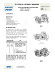
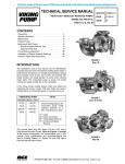
KK-124
INTRODUCTION
The illustrations used in this manual are for identification
purposes only and cannot be used for ordering parts. Obtain
a parts list from the factory or a Viking representative.
Always give complete name of part, part number and
material with model number and serial number of pump
when ordering repair parts. The pump model number and
serial number are on the nameplate.
In the Viking model number system, basic size letters are
combined with series number.
LL-124 – Shown with 180 Deg. Ports
UNMOUNTED PUMP
UNITS
J-124
K-124
KK-124
L-124
LQ-124
LL-124
LM-124
Units are designated by the
unmounted pump model numbers
followed by “Arrangement”
indicating drive style.
13-Direct Connected
53-Belt Driven
70-Commercial Speed Reducer
90-Commercial Gear Motor
This manual deals only with Series 120 and 124 Heavy
Duty Bracket Mounted Pumps. Pump specifications and
recommendations are listed in Catalog Section 3, series
124 Heavy Duty Bracket Mounted Pumps.
LM-124
VIKING PUMP, A Unit of Idex Corporation, 661 Grove Ave., Windsor, Ontario N9A 6M3 Canada
DANGER
BEFORE OPENING ANY VIKING PUMP LIQUID CHAMBER (PUMPING CHAMBER, RESERVOIR, RELIEF VALVE
ADJUSTING CAP FITTING ETC.) BE SURE:
1.
THAT ANY PRESSURE IN CHAMBER HAS BEEN COMPLETELY VENTED THROUGH SUCTION OR DISCHARGE
LINES OR OTHER APPROPRIATE OPENINGS OR CONNECTIONS.
2.
THAT THE DRIVING MEANS (MOTOR, TURBINE, ENGINE, ETC.) HAS BEEN “LOCKED OUT” OR MADE NONOPERATIONAL SO THAT IT CANNOT BE STARTED WHILE WORK IS BEING DONE ON PUMP.
3.
THAT YOU KNOW WHAT LIQUID THE PUMP HAS BEEN HANDLING AND THE PRECAUTIONS NECESSARY TO
SAFELY HANDLE THE LIQUID. OBTAIN A MATERIAL SAFETY DATA SHEET (MSDS) FOR THE LIQUID TO BE
SURE THESE PRECAUTIONS ARE UNDERSTOOD.
FAILURE TO FOLLOW ABOVE LISTED PRECAUTIONARY MEASURES MAY RESULT IN SERIOUS INJURY OR DEATH.
ROTATION: Rotary gear pumps operate equally well in a clockwise or counterclockwise
rotation. The shaft rotation determines which port is suction and which is discharge. Port in
area where pumping elements (gear teeth) come out of mesh is suction port.
PRESSURE RELIEF VALVES:
1. Viking pumps are positive displacement pumps and must be provided with some sort of
pressure protection. This may be a relief valve mounted directly on the pump, an inline
pressure relief valve, a torque limiting device or a rupture disk.
2. There are relief valve options available on pump models. Options may include a return to
tank relief valve and a jacketed relief valve. Pumps equipped with a jacketed head are not
available with a relief valve.
3. If pump rotation is reversed during operation, pressure protection must be provided on both
sides of pump.
4. Relief valve bonnet (see page 11) must always point towards suction side of pump. If pump
rotation is reversed, remove pressure relief valve and turn end for end. Figures 2 and 3
show 2 possible configurations, both have side suction and top discharge. A right-hand
pump turns in the opposite direction to the left-hand pump.
5. Pressure relief valves cannot be used to control pump flow or regulate discharge pressure.
SPECIAL INFORMATION
SPECIAL MECHANICAL SEALS can be installed either next to rotor hub or behind the bracket
bushing.
Extra care must be taken in repair of pumps with mechanical seals. Read and follow all special
information supplied with pump.
MAINTENANCE
Series 124 pumps are designed for long, trouble-free service life under a wide variety of
application conditions with a minimum of maintenance. The points listed below will help provide
long service life.
Figure 2, Right Hand Pump
LUBRICATION: All pumps are greased at the factory. External lubrication must be applied
slowly with a grease gun to all lubrication fittings every 500 hours of operation with multi-purpose
grease. Do not over-grease. Applications involving very high or low temperatures will require
other types of lubrication. Consult factory with specific lubrication questions.
PACKING ADJUSTMENT: New packed pumps require initial packing adjustment to control
leakage as packing “runs in”. The adjustment should be made while the pump is operating with
normal operating pressure on the discharge of the pump. Make adjustments carefully and do not
over-tighten packing gland. Evenly tighten the gland fasteners until the leak is reduced to a very
slow drip. If over tightened the packing will over heat, score the shaft and reduce life. After initial
adjustment, inspect periodically for increased leakage and re-adjust. Once the gland has been
tightened to the stuffing box face, loosen the packing gland and add one ring to the stuffing box,
then adjust again. Refer to instructions under Disassembly, page 5, and Assembly, page 6,
regarding repacking pump.
2
Figure 3, Left Hand Pump
CLEANING PUMP: Keep pump as clean as possible. This will facilitate inspection,
adjustment and repair work and help prevent overlooking a dirt covered grease fitting.
STORAGE: If pump is to be stored, or not used for six months or more, pump must be
drained and a light coat of lubricant and rust preventative suitable to the application must
be applied to all internal pump parts. Lubricate fittings and apply grease to pump shaft
extension. Rotating the pump shaft by hand, one complete revolution every 30 days to
circulate the oil.
SUGGESTED REPAIR TOOLS: The following tools must be available to properly repair
Series 124 pumps. These tools are in addition to standard mechanics’ tools such as openend wrenches, pliers, screwdrivers, etc. Most of the items can be obtained from an
industrial supply house.
1. Soft Headed hammer
Figure 4, Idler bushing press fit
2. Allen wrenches (some mechanical seals and set collars)
3. Packing hooks, flexible (packed pumps)
Small for 0.25 inch and 0.31 inch cross section packing
Large for 0.38 inch and up cross-section packing
4. Mechanical seal installation sleeve
5. Bearing locknut wrench or hammer and punch
6. Spanner wrench, adjustable pin type for use on end caps (Source: #482 J. H. Williams
& Co. or equal) or hammer and punch
7. Brass bar
8. Arbor press
Strainers: Use a strainer on the suction side of the pump to prevent foreign material from
entering the pump causing damage to the gears, and casing or lock-up the pump. Keep the
strainer on the suction side of the pump clean and free of debris. A blocked strainer will not
allow sufficient liquid to reach the pump. The lack of liquid reaching the pump will create
cavitation. Cavitation is when the liquid vaporizes on its way to the pump, then returns to a
liquid form on the surfaces of the pump. This is very noisy, damaging to a pump, and
seriously affects the output.
Figure 5, Pressing the idler pin
Figure 6, Inner lipseal orientation
Figure 7, Outer lipseal orientation
3
PACKED PUMPS
Exploded View for Packed Models: J-124, K-124, KK-124, L-124, LQ-124, LL-124,
and LM-124 (Model LL-124 shown)
ITEM
1
2
3
4
5
6
7
8
9
NAME OF PART
Lip Seal (Outer)
End Cap (Outer)
Lock nut
Lock washer
Ball Bearing
Bearing Spacer
Lip Seal (Inner)
End Cap
Setscrew
ITEM
10
11
12
13
14
15
16
17
18
NAME OF PART
Grease Fitting
Pipe Plug
Bracket
Packing Gland Fasteners
Packing Gland
Packing Rings
Bracket Bushing
Casing Gasket
Casing
Packing area cross-section
Gland
Packing Rings
4
ITEM
19
20
21
22
23
24
25
26
NAME OF PART
Rotor and Shaft Ass’y
Idler
Idler Bushing
Idler Pin
Casing Gasket
Head
Head Fasteners
Grease Fitting
DISASSEMBLY
1. Mark head and casing before disassembly to insure proper reassembly. The idler pin,
which is offset in pump head, must be positioned toward and centered between the port
connections to allow for proper flow of liquid through pump. Figure 18, page 9.
Remove head from pump. Do not allow idler to fall from idler pin. Tilt top of head back
and down when removing to prevent this. The idler and bushing should stay on the idler
pin. If pump is furnished with pressure relief valve, remove it from the head and refer to
Pressure Relief Valve Instructions, page 11.
The gaskets must be totally removed. Use new gasket when assembling pump.
1. Remove idler and bushing assembly from the idler pin.
1. Loosen the setscrews on the bearing end of the bracket, and remove the outer end cap.
Figure 22, page 10.
2. Remove the packing gland fasteners.
3. Insert a length of hardwood or brass through a port opening between rotor teeth to keep
shaft from turning. Bend up the tab of lock washer, which is engaging the lock nut, and
with a lock nut wrench remove the lock nut and lock washer from the shaft. Remove the
wood or brass from the rotor.
Figure 8, Pressing the Bracket bushing
4. Remove the packing gland fastener, and pull the gland out of the stuffing box.
5. Tap the shaft forward with a soft headed hammer, and pull it out of the bracket and
bushing assembly being careful not to damage the bracket bushing.
6. Remove the packing gland through the side of the bracket.
7. The packing may be removed with a packing puller. In some cases two pullers will be
required, or pushed out with a chisel and a hammer from the bushing side (be careful
not to damage the bushing). If removal still cannot be done with the pullers or chisel,
stand the pump on the bearing end of the bracket and press the bushing out through
the packing area. This will remove all of the packing with the bushing.
8.
Remove the inner end cap with lip seal. To remove the bearing from the bracket. Tap
the bearing forward with a soft headed hammer
9.
Clean all parts thoroughly and examine for wear and damage. Check lip seals, ball
bearing, bushings and idler pin and replace if necessary. Check all other parts for nicks,
burrs, excessive wear and replace if necessary.
Figure 9, Alternate the packing cuts
10. Wash bearings in clean solvent. Blow out bearings with compressed air. Do not allow
bearings to spin; turn them slowly by hand. Spinning bearings will damage race and
balls. Make sure bearings are clean, then lubricate with non-detergent SAE 30-weight
oil and check for roughness. Roughness can be determined by turning the inner and
outer race opposite directions by hand. Note if the motion is smooth and free or rough
and stiff. Smooth and free is desired. Figure 10.
11. The casing can be checked for wear or damage while mounted on the bracket.
12. The bracket bushing can also be inspected while still in the bracket. If replacement is
necessary, stand the unit on the casing and push the bushing out with a round bar
through the bearing end of the bracket.
Figure 10, Pushing in the packing rings into
the stuffing box
5
ASSEMBLY
Viking supplies pumps with a wide variety of bushing materials. These materials should not
all be treated the same. See “Bushing Material” page 10.
1. Press the idler bushing into the idler gear. If carbon graphite, refer to Installation of
Carbon Graphite Bushings, page 10. Figure 4, page 3
2. Using the idler and bushing assembly as a guide, press the idler pin into the head with
the tapped hole into the head and the lubrication hole or groove directed toward the
center of the crescent on the head. Figure 5, page 3
3. Press lip seals into the end caps, figure 6 and 7 page 3 (lip facing away from the
threads). Put the inner end cap in the bracket as shown in figure 11.
4. Install the bracket bushing. If bracket bushing has a lubrication groove, install bushing
with the lubrication hole aligned with the grease-fitting hole on the bracket. Figure 8,
page 5. If carbon graphite, refer to Installation of Carbon Graphite Bushings, page 10.
Figure 11, Endcap and inner lip seal
5. Use only new packing suitable for the liquid being pumped. Install the packing,
staggering the joints from one side of shaft to other, Figure 9, page 5. If needed,
lubricate packing rings with oil, grease or graphite to aid assembly. A length of pipe will
help to seat each packing ring, Figure 10, page 5.
6. Install packing gland, cap screws and nuts. Make sure the gland is installed square and
nuts are loosely assembled. Figure 12. Refer to “Packing Adjustment” page 2 after the
pump is assembled and installed.
7. Coat the shaft of the rotor and shaft assembly with non-detergent SAE 30 weight oil.
Start the end of shaft in the bracket bushing while turning counter clockwise, slowly
push the shaft through the packing. Continue until the rotor and shaft assembly cannot
move any further.
8. Slide bearing spacer over shaft, past the threads and against the shoulder on the shaft.
Figure 13.
Figure 12, Gland & shaft installed
9. With the ball bearing on the bench, hold the grease gun tip against the bearing and
apply grease to the top of the bearing all the way around the diameter. Place the ball
bearing on the shaft and push it against the bearing spacer. See figure 14, page 8. Hold
the grease gun tip against the bearing and apply grease to the top of the bearing as
before.
10. Put the lock washer and lock nut on shaft. Insert length of hardwood or brass through
port opening between rotor teeth to keep shaft from turning. Tighten the lock nut. One
tab of the lock washer will line up with a slot in the lock nut. Bend that tab into the slot.
Figure 15, page 8.
11. Put the outer end cap and lip seal assembly on the shaft and turn it into the bracket until
it is against the bearing.
12. Place one casing gasket and the bracket on the casing. Start the bolts into the casing
threads, Figure 16, page 8. Turn the shaft to determine if the rotor is rotating freely
inside the casing. If not, tap the casing with a softheaded hammer until the rotor does
not touch the casing. Tighten the bolts evenly on the casing.
13. Install the head and idler assembly on pump with two casing gaskets between them. If
the pump head and casing were marked before disassembly simply match up the
markings. If not, be sure the idler pin, which is offset in pump head, is positioned
between the ports. Tighten head cap screws evenly. Figure 1 page 2 shows the pin and
crescent in the appropriate orientation to the ports.
14. Adjust pump end clearance. Refer to End Clearance Adjustment, page 10.
15. Lubricate all grease fittings with multi-purpose grease.
6
Figure 13, Bearing spacer
MECHANICAL SEAL PUMPS
Exploded View for Mechanical Seal Models: J-124, K-124, KK124, L-124, LQ-124, LL-124, and LM-124 (Model LL-124 shown)
ITEM
1
2
3
4
5
6
7
8
NAME OF PART
Lip seal (Outer)
End cap (Outer)
Lock Nut
Lock Washer
Ball Bearing
Bearing Spacer
Lip Seal (Inner)
End cap (Inner)
ITEM
9
10
11
12
13
14
15
16
NAME OF PART
ITEM
Set Screws
Grease Fitting
Pipe Plug
Bracket
Retainer Fasteners
Seal Seat Retainer
Retainer O-ring
Stationary Seal Seat
17
18
19
20
21
22
23
24
Mechanical Seal Cross-Section
NAME OF PART
Rotating Seal Element
Seal Spring
Driving Ring
Set crews
Bracket Bushing
Casing Gasket
Casing
Rotor and Shaft Ass’y
ITEM
25
26
27
28
29
30
31
NAME OF PART
Idler
Idler Bushing
Idler Pin
Casing Gasket
Head
Head Fasteners
Grease Fitting
Spring
Seal Rotating Member
Shaft
Access hole plug
Setscrew
Tapered Installation Sleeve
Retainer
O-ring
Stationary Rotating
Element
Element
Spring
Driving
Ring
Coat the shaft, tapered installation sleeve and inner diameter of
mechanical seal with lubricant as recommended by your seal
supplier.
7
DISSASSEMBLY
1. Mark head and casing before disassembly to insure proper reassembly. The idler pin,
which is offset in pump head, must be positioned toward and equal distance between
port connections to allow for proper flow of liquid through pump.
2. Remove head from pump. Do not allow idler to fall from idler pin. Tilt top of head back
when removing to prevent this. If pump is furnished with pressure relief valve, it need
not be removed from head or disassembled at this point. Refer to Pressure Relief Valve
Instructions, page 11
The gaskets must be totally removed. Use new gaskets when assembling a pump.
3. Remove idler and bushing assembly from the head and idler pin.
4. Loosen the setscrews on the end caps and remove the outer end cap only. Figure 22,
page 10.
5. Insert length of hardwood or brass through port opening between rotor teeth to keep
shaft from turning. Bend up tab of Iockwasher and remove the lock nut and lock washer
from shaft.
Figure 14, Ball bearing
6. Remove the fasteners from the seal seat retainer and pull it away from the seal
chamber to free the spring on the seal. Remove the pipe plug from the bracket in the
side of the seal chamber and loosen the 2 setscrews on the driving ring through the
tapped hole in the side of the seal chamber.
7. Carefully tap the shaft forward and remove the rotor and shaft assembly from the pump.
Hold the seal seat retainer so that it does not fall and damage the stationary seat of the
seal.
8. Remove the rotating seat of seal and the driving ring from the bracket.
9. The stationary seal seat can be removed from the seal seat retainer by gently prying
the seal seat out with a small flat screwdriver.
10. Remove the inner end cap.
11. To remove the bearing from the bracket. Tap the bearing forward with a soft headed
hammer
Figure 15, Lock-nut & lock-washer
12. Clean all parts thoroughly and examine for wear or damage. Check lip seals, ball
bearing, bushing and idler pin and replace if necessary. Check all other parts for nicks,
burrs, excessive wear and replace if necessary.
13. Wash bearings in clean solvent. Blow out bearings with compressed air. Do not allow
bearings to spin; turn them slowly by hand. Spinning bearings will damage race and
balls. Make sure bearings are clean, then lubricate with non-detergent SAE 30 weight
oil and check for roughness. Roughness can be determined by turning outer race by
hand. Be sure shaft is free from nicks, burrs and foreign particles that might damage
bracket bushing. Scratches on shaft in seal area will provide leakage paths under
mechanical seal.
14. Casing and bracket bushing can be checked for wear or damage while assembled.
15. If needed, remove the bracket bushing with the casing still mounted by standing the unit
on the casing in a press and proceed to push the bushing out of the bracket.
Figure 17, Head mounted
Figure 16, Mounting the casing
Figure 18, Tighten down the outer
endcap
8
ASSEMBLY
Standard Mechanical Seal
The seal used in this pump is simple to install and good performance will result if care is taken during
installation.
The principle of the mechanical seal is that contact between the rotary and stationary members.
These parts are lapped to a high finish and their sealing effectiveness depends on complete contact.
Viking furnishes a number of heavy-duty pumps with special mechanical seals. These special seals
are not discussed in TSM124. Information is available by contacting the factory. When requesting
special seal information, be sure to give pump model number and serial number.
Figure 19, Stationary set install
Viking supplies pumps with a wide variety of bushing materials. These materials should not all be
treated the same. See “Bushing Material” page 10.
1.
Perform steps 1 through 4 of Packed Pump Assembly.
Never touch sealing faces with anything except clean hands or clean cloth. Minute particles
can scratch the seal faces and cause leakage.
2.
Press the stationary seat into the seal seat retainer while protecting the face as pictured in
figure 19.
Prior to installing rotating portion of mechanical seal, prepare and organize rotor shaft, head
and idler assemblies and appropriate gaskets for quick assembly.
Once rotating portion of mechanical seal is installed on rotor shaft, it is necessary to assemble
parts as quickly as possible to insure that seal does not stick to shaft in wrong axial position.
The seal should be expected to stick to the shaft after several minutes setting time.
Figure 20, Installing the Seal
3.
Clean the bracket seal housing bore and the shaft. Make sure both are free from dirt and grit.
Coat the inner diameter of the seal housing bore, and the shaft with a lubricant recommended
by your seal supplier.
4.
Place the sleeve installation guide on the shaft.
5.
Start the end of shaft in the bracket bushing and slowly push the shaft through. Continue until
the shaft begins to emerge from the seal chamber.
6.
Place the spring on driving ring and with the setscrews already started in the threads of the
driving ring, put the spring and ring on the shaft.
7.
Slide rotary member, lapped contact surface facing away from spring, over installation sleeve
on shaft until it is against spring. Do not compress spring.
8.
Place the seal seat retainer with the stationary seat facing the seal chamber on the shaft.
Figure 20, page 9.
9.
Guide the rotating element past the steps in the shaft, and over the tapered guide. Carefully push the rotor and shaft assembly all of the
way into the bracket.
Figure 21, Tightening the seal.
10. Remove the tapered installation sleeve from the shaft.
11. Do steps 8 through 14 of the "Packed Pump Assembly"
12. Push the spring into the seal chamber until the driving ring is visible through the tapped hole in the seal chamber. Then turn the shaft until
the setscrews can be tightened down.
13. Push the seal assembly into the seal chamber and attach the fasteners loosely. Figure 21.
14. Check that the retainer is centered and square with the shaft.
15. Tighten the fasteners evenly and in small increments.
16. Replace the pipe plug in the hole on the side of the stuffing box.
17. Pneumatic test your pump for leaks. See Page 12
18. Lubricate all grease fittings with multi-purpose grease.
9
INSTALLATION OF CARBON GRAPHITE BUSHINGS
When installing carbon graphite bushings, extreme care must be taken to prevent breaking. Carbon graphite is a brittle material and easily
cracked. If cracked, the bushing will quickly disintegrate. Using a lubricant and adding a chamfer on the bushing and the mating part will help in
installation. The additional precautions listed below must be followed for proper installation:
1. A press must be used for installation.
2. Lubricate the bushing and bore with soapy water.
3. Be certain bushing is started straight.
4. Do not stop pressing operation until bushing is in proper position. Starting and stopping will result in a cracked bushing.
5. Check bushing for cracks after installation.
BUSHING MATERIALS
Viking bushing material recommendations.
Material
Appearance
Bronze
Carbon
Iron
Nitralloy
Tungsten
Yellowish
Black
Steel
Steel
Steel
Installation
Lubricant
Not required
Soapy Water
Oil or anti-seize
Oil or anti-seize
Oil or anti-seize
Operating
Lubrication
Required
Not required
Required
Required
Not required
Figure 22, Loosening the set screws
END CLEARANCE ADJUSTMENT
1.
Loosen setscrews over outer and inner end caps. Figure 22.
2.
Turn inner end cap clockwise, viewed from shaft end, about 2 or 3 turns.
3.
Turn outer end cap clockwise until the rotor is tight against the head and the
shaft cannot be turned.
4.
Make a reference mark on bracket end, opposite a notch on outer end cap.
5.
Back off the outer end cap required number of notches to obtain the required
end clearance. Each notch is 0.0025 inches. Consult the factory for your
specific end clearance requirement. Tighten down the setscrews on the outer
and inner end caps.
Bearing Cross-section
Inner
Lipseal
Endcap
Outer
Lipseal
Bearing
Locknut
Lockwasher
10
Bearing Spacer
ITEM
1
2
3
NAME OF PART
Bonnet
Adjusting Screw
Lock nut
ITEM
4
5
6
NAME OF PART
ITEM
Bonnet o-ring
End cap
Spring Guide
7
8
9
NAME OF PART
Cap Gasket
Spring
Casing
ITEM
10
11
NAME OF PART
Poppet
Relief valve port gasket
PRESSURE RELIEF VALVE INSTRUCTIONS
DISASSEMBLY
Mark valve and head before disassembly to insure proper reassembly.
1. Remove bonnet.
2. Measure and record length of adjusting screw protruding out of the end cap.
3. Loosen lock nut and back out adjusting screw until spring pressure is released.
4. Remove relief valve cap, spring guide, spring and poppet from valve body. Clean and inspect
all parts for wear or damage and replace as necessary.
Figure 23, Poppet, spring, & spring retainer
ASSEMBLY
Reverse procedures outlined under Disassembly. If valve is removed for repairs, be sure to replace
in same position. Relief valve adjusting screw cap must always point towards suction side of pump.
If pump rotation is reversed, remove the relief valve and turn end for end. Refer to Figures 2, 3,
page 2.
PRESSURE ADJUSTMENT
If a new spring is installed or if pressure setting of pressure relief valve is to be changed from that
which the factory has set, the following instructions must be carefully followed:
1. Carefully remove the bonnet, which covers the adjusting screw. Figure 26, page 12.
2. Loosen the lock nut, which locks the adjusting screw so that the pressure setting will not
change during operation of pump. Figure 25, Page 12
3. Install a pressure gauge in discharge line for actual adjustment operation.
Figure 24, Spring & Retainer
4. Turn adjusting screw in to increase pressure and out to decrease pressure.
5. Closing a valve in the piping will stop all flow. A pressure gauge on the discharge port of the pump will show the maximum pressure that the
relief valve will allow while pump is in operation.
11
IMPORTANT
In ordering parts for pressure relief valve, always give model number and serial number
of pump as it appears on nameplate and name of part wanted. When ordering springs, be
sure to give pressure setting desired.
PNEUMATIC TESTING
1.
Seal the ports with pipe plugs or plates and gaskets. Be sure to provide a male air
line connection to one of the ports.
2.
Apply air pressure to the pump.
3.
Spray or brush the externals with soapy water and watch for growing air bubbles
around the seal, fitting, and gaskets. Figure 27.
4.
Relieve the pressure from the pump.
5.
Carefully disconnect the air supply.
6.
Remove the plugs or covers from the ports.
7.
Return the pump to service.
Figure 25, End cap, screw, & nut
Figure 26, Bonnet
Figure 27, Pneumatic testing
12
Troubleshooting
No Discharge:
Insufficient Discharge Volume
Insufficient Pressure
Loss of suction after a period
Of operation
Excessive power requirement
Noisy operation with good
Performance
Noisy operation with poor or
No performance
Leaking around the shaft
Pump priming may be required
Suction lift is too great
Relief valve is stuck open
Strainer needs cleaning
Wrong direction of rotation
Air leeks in suction
Speed is to slow
Relief valve is set to low
Suction lift too high for liquid handled. This is very important on hot or
volatile fluids
Suction line is not submerged
Suction piping too small in diameter, or foot valve is to small
Wrong rotation
Pump internals worn
Air or gases in suction piping
Viscosity is higher than expected
Relief valve set to low
Air or gases in the fluid
Pump internals are worn
Insufficient volume being pumped
Wrong rotation
Improper clearances in the internals
Suction line is leaking (letting air into the pump)
Packing is too loose or the mechanical seal is leaking
Leaking Gaskets
Viscosity to high
Discharge pressure is to high
Insufficient lubrication
Shaft or rotor bent, misalignment or packing gland is to tight
Misalignment of coupling
Worn bearings
Cavitation – Not enough fluid getting to the pump
Worn bearings or bushings
Packing is loose, or needs replacement
Mechanical seal is damaged or misaligned
Shaft is scored
Shaft is bent
13
PUMP INSPECTION REPORT
PUMP MODEL:
DATE:
SERIAL NUMBER:
CUSTOMER:
SALES ORDER NUMBER:
REFERENCE:
APPLICATION AND/OR PROBLEM:
DESCRIPTION
STANDARD
DIMENSIONS
ROTOR O.D.
ROTOR I.D.
ROTOR TOOTH LENGTH
IDLER O.D.
IDLER (BUSHING) I.D.
IDLER TOOTH LENGTH
IDLER PIN O.D.
SHAFT O.D.
SHAFT BUSHING I.D.
CRESCENT LENGTH
CASING I.D.
END CLEARANCE
COMMENTS & RECOMMENDATIONS:
14
EX. CL.
(IF ANY)
ACTUAL
WEAR
NOTES
15
TECHNICAL SERVICE MANUAL
HEAVY-DUTY BRACKET MOUNTED PUMPS
SERIES 120 and SERIES 124
SIZES J, K, KK, L, LQ, LL AND LM
SECTION 3
BULLETIN TSM-120-124-V
ISSUE A-2004
WARRANTY
Viking warrants all products manufactured by it to be free
from defects in workmanship or material for a period of one (1)
year from date of startup, provided that in no event shall this
warranty extend more than eighteen (18) months from the date of
shipment from Viking. If, during said warranty period, any
products sold by Viking prove to be defective in workmanship or
material under normal use and service, and if such products are
returned to Viking’s factory at Windsor, Ontario, transportation
charges prepaid, and if the products are found by Viking to be
defective in workmanship or material, they will be replaced or
repaired free of charge, FOB. Windsor, Ontario.
Viking assumes no liability for consequential damages of any
kind and the purchaser by acceptance of delivery assumes all
liability for the consequences of the use or misuse of Viking
products by the purchaser, his employees or others. Viking will
assume no field expense for service or parts unless authorized by
it in advance.
Equipment and accessories purchased by Viking from outside
sources which are incorporated into any Viking product are
warranted only to the extent of and by the original
manufacturer’s warranty or guarantee, if any.
THIS IS VIKING’S SOLE WARRANTY AND IS IN
LIEU
OF
ALL
OTHER
WARRANTIES,
EXPRESSED OR IMPLIED, WHICH ARE HEREBY
EXCLUDED, INCLUDING IN PARTICULAR ALL
WARRANTIES OF MERCHANTABILITY OR
FITNESS FOR A PARTICULAR PURPOSE. No
officer or employee of IDEX Corporation or Viking Pump
Canada is authorized to alter this warranty.
VIKING PUMP, A Unit of IDEX Corporation, 661 Grove Ave., Windsor, Ontario N9A 6M3 Canada