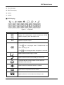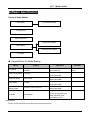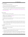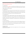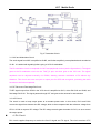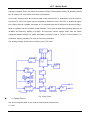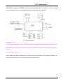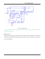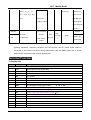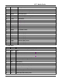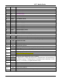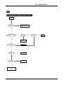
1
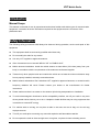
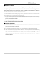
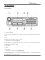
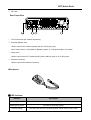
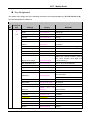
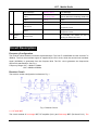
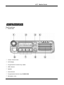
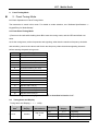
HYT Mobile Radio
Contents
Introduction............................................................................................................................................... 2
Safety Information .................................................................................................................................... 3
Radio Overview ........................................................................................................................................ 5
Software Specification ............................................................................................................................. 8
Circuit Description ................................................................................................................................. 19
Semiconductor Data............................................................................................................................... 24
Component Description......................................................................................................................... 29
Parts List 1 .............................................................................................................................................. 30
Tuning Description ................................................................................................................................. 93
Terminal Function................................................................................................................................. 105
Troubleshooting Flow Chart ............................................................................................................... 108
Disassembly and Reassembly for Repair.......................................................................................... 112
Exploded View ...................................................................................................................................... 115
Parts List 2 ............................................................................................................................................ 116
Packing .................................................................................................................................................. 117
PCB View ............................................................................................................................................... 118
Block Diagram ...................................................................................................................................... 118
Schematic Diagram .............................................................................................................................. 118
Specifications ....................................................................................................................................... 118
1
HYT Mobile Radio
Introduction
Manual Scope
This manual is intended for use by experienced technicians familiar with similar types of communication
equipment. It contains all service information required for the equipment and is current as of the
publication date.
Safety Information
The following safety precautions shall always be observed during operation, service and repair of this
equipment.
This equipment shall be serviced by qualified technicians only.
Do not modify the radio for any reason.
Use only HYT supplied or approved antenna.
Gain of antenna must not exceed 3dBi for VHF or 5.5dBi for UHF.
Mobile antenna Installation: Install the mobile antenna at least 82cm (32 inches) away from your
body, in accordance with the requirements of the antenna manufacturer/supplier.
Transmit only when people inside and outside the vehicle are at least the minimum distance away
from a properly installed, externally mounted antenna.
Mobile antenna substitution: Don’t substitute HYT supplied or approved antenna, or excessive radio
frequency radiation will result. Please contact your dealer or the manufacturer for further
instructions.
Please make sure there’s no stress on the antenna joint during transportation or installation.
To avoid electromagnetic interference and/or compatibility conflicts, turn off your radio in any area
where posted notices instruct you to do so. Hospital or health facilities may be using equipment that
is sensitive to external RF energy.
For vehicles with an air bag, do not place a radio in the area over an air bag or in the air bag
deployment area.
Turn off your radio prior to entering any area with explosive and flammable materials.
Do not expose the radio to direct sunlight over a long time, nor place it close to heating source.
2
HYT Mobile Radio
▇ Operation Guidelines
For vehicles equipped with electronic anti-skid braking systems, electronic ignition systems or electronic
fuel injection systems, interferences may occur during radio transmission. If the foregoing electronic
equipments are installed on your vehicle, please contact your dealer for further assistance to make sure
that radio transmission will not interfere with these equipments.
For radio installation in vehicles fueled by LP gas with LP gas container within interior of the vehicles, the
following precautions are recommended for personal safety.
1. Any space containing radio equipment shall be isolated by a seal from the space in which the LP gas
container and its fittings are located.
2. Remote (outside) fitting connections shall be used.
3. Good ventilation is required for the container space.
▇ Installation Guidelines
Vehicle installation: The antenna can be mounted at the center of a vehicle metal roof or trunk lid if
the minimum safe distance is observed.
Do not mount the mobile radio overhead or on a sidewall unless you take special precautions.
If the mobile radio is not properly installed, road shock could bump the radio loose, and the falling
radio could, in some circumstances, cause serious injury to the driver or a passenger. In case of
vehicle accidents, even when properly installed, the radio could break loose and become a
dangerous projectile.
3
HYT Mobile Radio
Radio Overview
Front Panel View
① Volume Control Knob
Turn the Volume Control Knob clockwise to increase the volume, or counter-clockwise to decrease the
volume.
② LCD
Please refer to the “LCD Display” section for details.
③ Programmable Functions Keys ([▲] / [▼])
The [▲] / [▼] keys are programmable with auxiliary functions by your dealer. Please refer to the
“Programmable Functions Keys” section.
④ LED Indicator
⑤ Speaker
⑥ Power Switch
⑦ Programmable Functions Keys ([P1]/[P2]/[P3]/[P4])
The [P1]/[P2]/[P3]/[P4] keys are programmable with auxiliary functions by your dealer. Please refer to
the “Programmable Functions Keys” section.
4
HYT Mobile Radio
⑧ Mic Jack
Rear Panel View
① 15-Pin Connector (for external expansion)
② External Speaker Jack
Used to connect the external speaker (for the 3.5mm plug only).
Note: Please refer to “Test Cable for Speaker Output” in “Tuning Description” for details.
③ Power Inlet
Used to connect the HYT -authorized DC power cable for input of 13.6V DC power.
④ Antenna Connector
Used to connect the external connector.
Microphone
▇ LED Indicator
Indicator
Description
Solidly glows red
The radio is transmitting signals.
Solidly glows green
The radio is receiving signals.
Flashes orange
The radio has received encoding squelch, select calls or 2-tone calls.
5
HYT Mobile Radio
▇ Programmable Function Keys
The P1-PF4 and ▲/▼ keys can be programmed with auxiliary functions below:
1. Off
2. CH Up
3. Channel Down
4. Zone Up
5. Zone Down
6. MONI A
7. MONI B
8. MONI C
9. MONI D
10. Display Frequency
11. Display Mode Switch
12. User Selectable Tone
13. Sel 2-Tone
14. TX Power
15. Scan
16. Add/Del
17. Reverse frequency
18. TalkAround
19. Selectable Squelch Level
20. Home Channel
21. Public Address
22. Scrambler
23. Compander
24. Emergency Call
25. HDC Encode
26. Lone Worker
27. Whisper
6
HYT Mobile Radio
28. Short Message
29. Rent Time Inquiry
30. AUX A
31. AUX B
▇ LCD Display
Figure 1
LCD panel
Indicator
Description
Displays CH number/name, zone number/name, DTMF
number, frequency, menu and options, etc.
Lo
Indicates low power output.
Press the Monitor key:
1. The
icon is displayed when CTCSS/CDCSS and
2-Tone decoding is off.
2. The
icon is displayed when the speaker is unmuted.
Appears when the radio begins to scan
Appears when the radio is transmitting a selected call.
C indicates that the current channel is in the scan list.
Z indicates multi zone scan.
Appears when the Scrambler feature is enabled.
Appears when the Compandor feature is enabled.
Appears when the current channel is already in use.
7
HYT Mobile Radio
Indicates the current channel is the priority channel. P•
indicates priority channel 1, P. indicates priority channel 2,
P: indicates priority channels 1 and 2.
8
HYT Mobile Radio
Software Specification
Frame of Radio Modes
Conventional Mode
User Mode
Tuning Mode
Model Set Mode
Wired Clone Mode
Clone Mode
Wireless Clone Mode
PC Mode
Keypad Entry for Mode Startup
Mode
Display
Operation
User Mode
Welcome Screen and then CH
number
The radio enters User Mode
upon power-on.
Panel Tuning Mode
TXHIGH
Power the radio on while
holding down P1.
Model Set Mode
DESTINA0
Power the radio on while
holding down P2.
Clone Mode
CLONE
Power the radio on while
holding down P3.
Firmware Version
Display Mode
Firmware Version VX.XX.XX
Power the radio on while
holding down P4.
PROGRAM
Connect the mobile radio to
PC via the programming
cable, and then send
commands via PC.
PC Mode
User Mode
Power on the radio and you will enter this conventional mode.
9
Remarks
Conventional
Mode
HYT Mobile Radio
Panel Tuning Mode
You can perform tuning in the following steps:
1) Power on the radio while holding down P1 to enter the tuning mode.
2) Use ▲/▼ to select the tuning item, and press P4 to enter.
3) After you enter the sub-item by pressing P4, use ▲/▼ to adjust the parameter, and press P4 to save
and enter the next sub-item; or press P1 to return to the previous menu without saving the settings.
Tuning items and display (***: 1-256): Please go to Tuning Description---Panel Tuning Mode---Tuning
items and Display for details.
Model Set Mode
You can go with operations in this mode as follows:
1) Power on the radio while holding down P2 to enter the Model Set mode. At this time, the LCD displays
“DESTINA.*”, where “*” represents the model number.
2) Use ▲/▼ to select the model number 0-5.
3) Press P4 to confirm your selected model number. The LED glows orange and the LCD displays
“WAIT”. After reset, the radio enters User mode.
Note:
1. Once a new model is set by pressing P4, the previously stored channel information (such as
frequency, CTCSS/CDCSS and functions assigned to each channel) will be cleared, and some
functions will also be changed. Therefore, do not perform this operation unless it’s very necessary
(e.g. when EEPROM is replaced).
Clone Mode
Data can be transferred from radio to radio either by wired cloning or wireless cloning. Operation
methods are given in the following paragraphs.
Wired Clone Mode
1)
Power on the source radio while holding down P3. The radio displays “CLONE” and enters Clone
mode or enters User Mode if Clone Mode is set OFF by your dealer.
2)
Press P3 to switch between Dealer Clone Mode and Factory Clone Mode, with “DEACLONE” and
“FACCLONE” displayed respectively. The radio restores its original display mode in 5 seconds.
Dealer Clone Mode is the default mode in which tuning data and embedded messages will not be
10
HYT Mobile Radio
cloned. However, in Factory Clone Mode, all data will be cloned.
3)
Connect two radios using a clone cable, and then turn on the target radio.
4)
Press P4 on the source radio to start cloning. LED on the source radio glows red, and it begins to
transmit data to the target radio. During the cloning process, LCD of the target radio displays
“PROGRAM” and its LED glows green. Upon completion of cloning, LCD of the source radio
displays “END”. And the target radio automatically enters User Mode after receiving all data.
5)
Press P4 on the source radio to return to Clone Mode, and “CLONE” is displayed. Repeat the above
steps for further wired cloning.
Wireless Clone Mode
1)
Power on the source radio while holding down P3. The radio displays “CLONE” and enters Clone
mode or enters User Mode if Clone Mode is set OFF by your dealer.
2)
Press P1 to enter Wireless Clone Mode. The LCD displays “WIRELESS” for about two seconds,
and then displays its channel frequency (wireless cloning is performed at this frequency). Press P1
again to return to Clone Mode, or press ▼ to switch the channel for wireless cloning.
3)
Press P3 to switch between Dealer Clone Mode and Factory Clone Mode, with “DEACLONE” and
“FACCLONE” displayed respectively. The radio restores its original display mode in 5 seconds.
Dealer Clone Mode is the default mode in which tuning data and embedded messages will not be
cloned. However, in Factory Clone Mode, all data will be cloned.
4)
For the target radio, repeat the above steps 1) and 2), and set its cloning frequency the same as that
of the source radio. Place the target radio close to the source radio, and press P4 of the source
radio to start cloning.
5)
The source radio is transmitting data to the target radio. During data transmission, the source radio
displays the percentage of the transmitted data, with red LED glowing. During data receiving, the
target radio displays the percentage of the received data and a “BUSY” icon, with orange LED
glowing.
6)
Upon completing of data transmission, LCD of the source radio displays “END” and the LED flashes
red. Press P1 to read the cloning frequency and repeat the above steps to continue. The target
radio enters User Mode automatically after receiving all data.
Note: Clone Mode can be enabled or disabled by your dealer. You can perform cloning only when such
mode is enabled by your dealer.
11
HYT Mobile Radio
Firmware Version Display Mode
Power on the radio while holding down P4. The LCD displays the firmware version accordingly. Release
P4 to enter User Mode automatically.
PC Mode
Connect the mobile radio to a PC using a programming cable. Data can be transmitted to the mobile
radio and saved in the EEPROM.
You can configure the parameters and tune the mobile radio via the programming software.
1) Once PC starts to transfer data to the mobile radio, “PROGRAMM” will be displayed on the LCD.
When the data is written to the mobile radio, the LED glows green; and when the data is read from
the mobile radio, the LED glows red. The mobile radio will reset automatically when programming is
completed.
2) The following items can be set via programming software:
TX High Power
TX Low Power
Maximum Frequency Deviation
CDCSS Balance
CTCSS Deviation (67.0Hz)
CTCSS Deviation (151.4Hz)
CTCSS Deviation (254.1Hz)
CDCSS Deviation
DTMF Deviation
MSK Deviation
Single Tone Deviation
RX Sensitivity
Squelch ON Level (9)
Squelch ON Level (3)
Squelch OFF Level (9)
Squelch OFF Level (3)
12
HYT Mobile Radio
Key Assignment
Your dealer may assign one of the following functions to the programmable key (P1/ P2/ P3/ P4/ ▲/ ▼).
See the table below for reference.
Key Assignment
Function
No.
Key
1
P1-P4
&
▲/▼
Settings
Remarks
Display
Off
No function
CH Up
CH Information
Channel up
CH Down
CH Information
Channel down
Zone Up
Zone Information
Zone up
Zone Down
Zone Information
Zone down
Monitor
A:
Monitor
Unmute
–
MONI A
MoniA Icon
Momentary
MONI B
MoniB Icon
Monitor B: Monitor Unmute – Toggle
MONI C (default)
MoniC Icon
Monitor C: Carrier Unmute – Momentary
MONI D
MoniD Icon
Monitor D: Carrier Unmute – Toggle
Display Frequency
CH Frequency
Displays the channel frequency
Displays the channel number, channel
label, zone number, zone label and
Display Mode Switch
Mode Information
channel frequency.
User Selectable Tone
UST Information
Tone 01-32 (CTCSS/CDCSS)
Sel 2-Tone
2-Tone Information
Selects 2-Tone encode
TX Power
Power Icon
Displays when the TX power is low
Scan
SCAN and Icon
Scan
Adds
Add/Delete
or
deletes
scan
channel
non-scan status
CH Information
Temporarily deletes nuisance channel
Reverse
RE and CH Number
Reverse frequency
Talk Around
TA and CH Number
Talk Around
SEL SQL
SQL Level
Selects squelch level
HOME
and
CH
Home CH
Number
Home Channel
Public Address
PA
Public Address
Scrambler
Scrambler Icon
Scrambler
Compander
Compander Icon
Compander
Emergency Call
Emergency
Emergency Call
HDC Encode
HDC Menu
HDC call
Lone Worker
LONE ON/OFF
Lone Worker
Whisper
WHISP ON/OFF
Whisper
13
in
HYT Mobile Radio
Short Message
Message Menu
Short Message
Inquiry
Remaining Time
Inquires about the remaining rental time
AUX A
AUX A
AUX A
AUX B
AUX B
AUX B
Remaining
2
HOOK/ MONI
Rental
Time
This option should be selected when palm
Hook Check
microphone is used.
This option should be selected when desktop
Monitor
3
Selector
Knob
microphone is used.
For controlling the volume as well as
Selector Knob
selecting the channel and zone
Circuit Description
Frequency Configuration
The receiver utilizes double conversion superheterodyne. The first IF is 49.95MHz and the second IF is
450KHz. The first local oscillator signal is supplied by the PLL circuit, while the second local oscillator
signal (49.5MHz) is generated from the frequenc MHz The PLL circuit generates the frequencies
required for transmission. See Fig.1.
Frequency Range VHF: 136MHz-174MHz
UHF: 400MHz-470MHz;
Receiver Circuit
The receiver section configuration is shown as Fig. 1.
Fig. 1 Receiver Circuit
2.1 RF AMP BPF
The circuit consists of front-stage BPF, RF amplifier (Q111) and final-stage BPF (D110 and D111). The
14
HYT Mobile Radio
bandpass frequency range varies with the radio models. The BPF is used to eliminate unwanted signals
and let only wanted signals go to the mixer.
2.2 First Mixer Circuit
The signal output from RF AMP&BPF is mixed with the first LO signal from the PLL circuit at the mixer
(D112) to generate a 49.95MHz first IF signal. Then the first IF signal will feed through a crystal filter
(IF200) to further remove spurious signals.
2.3 IF Amplifier Circuit
After amplified at Q113, the first IF signal enters IC102 (TA31136FN), where it is mixed with the second
LO signal (50.4MHz) to generate a 450KHz second IF signal. Then the second IF signal feeds through a
pair of ceramic filters (N: CF202; W: CF203) where unwanted signals are removed. Finally the signal
goes to the frequency discriminating circuit of IC102 to output audio signal from Pin 9.
2.4 Audio Amplifier Circuit
The audio signal from IC102 is amplified and filtered at IC402, and then amplified again at IC401 (the
received signaling is separated and sent to CPU for decoding). Then the signal passes through Q406
(AF MUTE), and enters IC405 for further amplification. After the volume is controlled at K301 on the
control panel, and SP MUTE is controlled at Q511, the signal feeds into IC511 to output audio signal to
drive the speaker.
2.5 Squelch Control Circuit
One flow of the audio signals from IC102 feeds into IC102 (from Pin8) for amplification, filtering and
rectification, and then a SQL level is derived. Then the SQL level is sent to CPU (IC502) for comparison
with the reference level to generate a level which controls AFMUTE and SP MUTE. The level controls
Q406 and Q511 to open or close the audio channel.
Transmitter Circuit
The transmitter circuit is composed of MIC circuit, modulation circuit, RF driver, final-stage power
amplifier circuit and APC circuit.
15
HYT Mobile Radio
Fig. 2 Transmitter Circuit
3.1 MIC and Modulation Circuit
The audio signal from MIC is amplified at IC405, and further amplified, pre-emphasized and encoded at
IC 401. It is added with signaling before going to VCO for modulation.
The DI modulation circuit is composed of IC407 and peripheral circuits (see the figure above). The signal
goes to the DI modulation circuit via the TXAF_DI port, and then goes to the VCO unit. The signal
amplitude can be adjusted manually via VR802, allowing accurate modulation of DI without any
distortion. This circuit can serve as input or output port for GPS and encryption, promoting the radio
functions to be further expanded.
3.2 RF Driver and Final-stage PA Circuit
TX-RF signal output from Q703 in the VCO circuit is amplified at Q101, driver PA Q110 and Q109, and
final-stage PA IC101. The signal passes through LPF and goes to the antenna for transmission.
3.3 APC Circuit
The circuit is used to keep output power at a constant preset value. In this circuit, D101 and D102
convert the signal from detector into DC voltage, which is then compared with the reference voltage from
CPU in IC104 to output a DC voltage. The DC voltage controls gate electrode of IC101, so as to control
the output power.
4. PLL Circuit
PLL circuit supplies frequency to receive the first LO signal and TX signal. The circuit consists of TX
16
HYT Mobile Radio
frequency oscillator (Q701), RX frequency oscillator (Q702), buffer amplifier (Q703), RF amplifier (Q102),
PLL IC (IC801), LPF and TX/RX VCO switch (Q704/Q706).
In TX mode, IC502 provides the frequency data to and activates PLL IC. Meanwhile, Q704 is turned on
to activate TX VCO. The output signal is amplified by Q703 and Q102. Then PLL IC divides the signal
into 2.5KHz, 5KHz or 6.25KHz. And phase of it is compared with that of reference frequencies 2.5KHz ,
5KHz or 6.25KHz from the 16.8MHz crystal oscillator. The crystal oscillator has operating frequency of
16.8MHz and frequency stability of 2.5ppm. The frequency control voltage output from the phase
comparator passes through LPF (Q802 and Q803), and then is sent to TX VCO. In the meantime, TX
modulation signal is passed to TX VCO for frequency modulation.
The working principle of RX mode is similar to that of TX mode.
Fig. 3 PLL Circuit
5. Control Circuit
The circuit comprises CPU circuit, reset circuit and power control circuit.
5.1 CPU
17
HYT Mobile Radio
IC120 (CPU) operates at 9.8304MHz, and controls EEPROM (IC501), RX circuit, TX circuit, control
circuit and display circuit, as well as data transmission with peripheral equipment.
Fig. 4 Control Circuit
5.2 Reset Circuit
The reset circuit consists of a reset IC (CN813LESA) and peripheral circuits. When a breakdown occurs
due to change of external voltage, the CPU would automatically reboot your radio through the reset IC
(IC901).
5.3 Power Control Circuit
Power supply of the radio is derived from +B. D515 and D516 are diodes for over-voltage protection. The
power can be switched on or off via software (see the figure below):
18
HYT Mobile Radio
Fig. 5 Power Supply Circuit
Vout supplies power for IC601, IC602 and IC803, which generate 8V, 5V and 3.3V voltage respectively
to supply the whole circuit.
6. Display Circuit
Display circuit comprises CPU (IC502), LCD, LED and other components. Application can be operated
manually through programmable keys P1-P4 as well as ▲ and ▼. Channel information is displayed on
the 14-segment display.
19
HYT Mobile Radio
Semiconductor Data
1. Positive voltage regulator: TA7805F (Power Unit IC602), TA7808S (Power Unit IC601)
2. EEPROM: CAT24C256WI 256K CATALYST (CPU Unit IC501)
2-1. Pin Function
Pin Function
Pin No.
Name
I/O
Function
1~3
A0~A2
I
Address input
4
GND
5
SDA
I/O
Serial data input/output
6
SCL
I
Serial clock input
7
Write Protect
Write protect
8
VCC
+5V
Ground
20
HYT Mobile Radio
3.
Audio processor: AK2346 (AFPwr Unit IC404)
Pin Function
Pin No.
Pin Name
I/O
Function
1
AGNDIN
I
Analog ground input
2
AGND
O
Analog ground output
3
TXIN
I
TX audio signal input
4
TXINO
O
TXA1 feedback output
5
LIMLV
I
Limit level tuning
6
EXTLIMIN
I
External signal input for pre-limiter
7
MOD
O
Modulated TX signal output
8
VSS
9
TCLK
O
Clock output pin for MSK transmission data
10
TDATA
I
MSK transmission data input
Data are latched synchronizing with the TCLK
rising edge.
11
DI/O
I/O
Serial data input and output
Input for register setting data and output for MSK
receiving data
12
RDF/FC
O
Rx flag, frame detection signal output pin
13
SCLK
I
Clock input
14
DIR
I
Serial data input
15
XOUT
I
Crystal oscillator input pin
16
XIN
17
VDD
18
EXPOUT
O
Signal output (after audio processing)
19
RXAFIN
I
RX audio input pin
20
RXAF
O
RX audio output pin
21
RXLPFO
O
Rx LPF output pin
22
RXINO
O
RXA1 feedback output pin
23
RXIN
I
Demodulated signal input pin
24
TEST
I
Test register control input pin
Ground
I/O
Crystal oscillator input/output pin
Positive power supply pin
4. Audio Power Amplifier: TDA7297D(AFPwr Unit IC511)
Pin Function
Pin No.
Name
I/O
Function
1
PW GND
2
OUT1+
3
N.C
4
N.C
5
OUT1-
O
Output 1-
6
VCC
I
Supply voltage
7
IN1
I
Input 1
Power ground 1
O
Output 1+
.
21
HYT Mobile Radio
8
MUT
I
Operating Switch
9
STAND-BY
I
Operating Switch
10
PW GND
Power ground 2
11
PW GND
Power ground 3
12
N.C
13
SGND
14
IN2
I
Input 2
15
VCC
I
Supply voltage
16
OUT2-
O
Output 2-
17
N.C
18
N.C
19
OUT2+
20
PW GND
5.
.
O
Output 2+
Power ground
LCD driver: PCF8576DH (Display Unit IC501)
Pin No.
1
Pin Name
I/O
Function
NC
2~7
S34~S39
O
LCD output
8~9
NC
10
SDA
I/O
I2C bus serial data input/output
11
SCL
O
I2C bus clock output
12
NC
13
NC
14
VDD
15
OSC
I
Internal quartz crystal oscillator enable input
A0~A2
I
Address line
19
SA0
I
I2C bus slave address (bit 0)
20
Vss
Ground
21
VLCD
5C power supply
22~24
NC
25~28
BP0~BP3
O
LCD bottom board output
29~32
S0~S4
O
LCD output
O
LCD output
16~18
33
34~47
48
5.
Signal ground
Power Supply
NC
S5~S18
NC
49, 50
S19, S20
O
LCD output
51~64
S21~S34
O
LCD output
Amplifier: TA75W558FU (AFPr Unit IC404), TC75W51FU (AFPr Unit IC402, AFPr Unit IC405, AFPr
Unit IC403), TA75S01F (RF Unit IC1037), TA75W01FU (RF Unit IC404).
6.
IF detector: TA31136FN (RF Unit IC102).
22
HYT Mobile Radio
7.
Dual D-type trigger: TC4013BF (AFPwr Unit IC512).
8.
RF PLL frequency synthesizer: MB15A02 (PLL Unit IC801).
9. Reset IC: CN813LESA (Reset Unit IC901)
10. CPU: SCM M3062LFGPGP (CPU Unit IC502)
Pin Function
Pin No.
Port
Pin Name
I/O
Function
1
P94/DA1
APC
O
Modulation sensitivity output
2
P93/DA0
DTMF
O
DTMF/2-Tone/5-Tone/BEEP output
3
P92/TB2in
2TN/5TN
I
2-Tone/5-Tone decoded pulse input
4
P91
AFDIO
I/O
AK2346 data input/output
5
P90
AFSCLK
O
AK2346 Clock output
6
BYTE
BYTE
I
+5V (5C)
7
CNVSS
CNVSS
I
Ground (via 0 resistance)
8
P87
PA
O
MIC PA switch control
9
P86
HMBL
O
Palm MIC backlight control
10
RESET
RESET
I
Reset
11
XOUT
XOUT
O
Clock output
12
VSS
VSS
I
Ground
13
XIN
XIN
I
Clock input
14
VCC
VCC
I
+5V
15
P85/NMI
NMI
I
NMI
16
P84/INT2
AFRDF
I
MSK RX detect for baseband chip
17
P83/INT1
DTMFSTD
18
P82/INT0
AUX1
19
P81/TA4in
SBC
20
P80/TA4out CTC_OUT
O
CDCSS balance output
21
P77/TA3in
SPMUTE
O
SP Mute control
22
P76/TA3out CTC_PLL
O
CTCSS/CDCSS modulation output
23
P75/TA2in
O
External MIC control
24
P74/TA2out AFTDATA
O
MSK serial data output of baseband chip
25
P73/TA1in
I
MSK clock input of baseband chip
26
P72/TA1out AFDIR
O
Baseband chip control
27
P71/RXD2
RXD2
Not used
28
P70/TXD2
TXD2
Not used
29
P67/TXD1
TXD1
O
Serial data output
30
P66/RXD1
RXD1
I
Palm MIC HOOK input/serial data input
31
P65
AUX4
I/O
AUX 4
32
P64
AUX5
I/O
AUX 5
33
P63
TXD2
O
Acc comm0 (serial data output)
34
P62
RXD2
I
Acc comm0 (serial data input)
35
P61
MICDAT
O
Palm MIC key code output
EMICC
AFTCLK
H: PA
Not used (left open)
I/O
AUX 1
Power switch control
23
H: Off
L: On
H: Mute
H: External MIC
L: PTT On
L: On
HYT Mobile Radio
36
P60
AUX2
I/O
37
P57
RDY
I
38
P56
NC
Not used (left open)
39
P55
HOLD
Not used (left open) (used for downloading)
40
P54
NC
Not used (left open)
41
P53
NC
Not used (left open)
42
P52
RD
43
P51
NC
44
P50
WR
O
External expansion for writing signal (not used)
45
P47
HNC
O
Horn alert control
46
P46
SHIFT
O
Clock frequency shift
47
P45
W/N
O
Wideband/Narrowband switch
48
P44
CS0
49
P43
MicMute
O
MIC Mute
50
P42
KEYBL
O
Keypad backlight control
51
P41
UP/LED4
O
UP/LED4
52
P40
LED6
O
LED6
53
P37
LCDCI/LED3
I/O
LCD Driver CI PIN/LED3
54
P36
DOWN/LED5
O
DOWN/LED5
55
P35
LCDCL/LED2
O
LCD Driver CL PIN/LED2
56
P34
LCDBL/LED0
O
LCD Driver BL PIN/LED0
57
P33
LED7
O
LED7
58
P32
LCDCE/LED1
O
LCD Driver CE PIN/LED1
59
P31
RLED
O
Red indicator
60
VCC
VCC
I
+5V
61
P30
GLED
O
Green indicator
62
VSS
VSS
I
Ground
63~66
A7~A4
A7~A4
67
P23
PLLDAT
O
PLL data output
68
P22
PLLCLK
O
PLL clock output
P21
SLED
O
Scan status indicator
P20
PLED
O
High/Low power indicator
71
P17
8RC
O
8R power supply control
H: RX
72
P16
8TC
O
8T power supply control
H: TX
73
P15
RX
O
TX/RX VCO switch
74
P14
EEPDAT
I/O
EEPROM data input/output
75
P13
EEPCLK
O
EEPROM clock output
76
P12
PLLUL
I
PLL unlock detect
77
P11
PLLSTB
O
PLL strobe output
78
P10
AFMUTE
O
RX audio mute
79
P07
/IGN
I
Ignition sensor input
80
P06
PWR
I
Power On/Off key
69
70
O
AUX 2
Pulled Up
External expansion for reading signal (not used)
Not used (left open)
H: On (not used)
H: On
H: Wideband
Not used (left open)
H: Mute
Not used (left open)
24
L: RX
L: Unlock
L: Lock
H: Mute
H: Off L: On
L: On
HYT Mobile Radio
81
P05
TYPE
I
selection input
82
P04
NC
83
P03
P4
I
P4 key input
L: On (external resistor pulled up)
84
P02
P3
I
P3 key input
L: On (external resistor pulled up)
85
P01
P2
I
P2 key input
L: On (external resistor pulled up)
86
P00
P1
I
P1 key input
L: On (external resistor pulled up)
87
AN7
Not used (left open)
88
AN6
Not used (left open)
89
AN5
Reserved for DTMF decoding
90
AN4
Reserved for DTMF decoding
91
AN3
Temp
I
Temperature data input
92
AN2
RSSI
I
RSSI input
93
AN1
SQL
I
SQL analog input
94
AVss
AVss
95
AN0
TI
I
CTCSS/CDCSS signal input
96
VREF
VREF
I
Reference voltage input
97
AVCC
AVCC
I
+5V
98
P97/Sin4
AUX3
I/O
AUX 3
99
P96/Sout4
AUX6
I/O
AUX 6
100
P95/Clk4
APCO
O
Audio PA control
Not used (left open)
Ground
25
HYT Mobile Radio
Component Description
1. TX-RX Unit
Ref. No.
Part Name
Type
Description
IC101
IC
Power module
Power module
IC501
IC
AT2408N12.5S
EROM
IC401
IC
AK2346
Audio processor
IC404
IC
TA75W558FU
Dual operational amplifier
IC403
IC
TC75W51FU
Dual operational amplifier
IC803
IC
XC62FP3302P
Positive voltage regulator
IC602
IC
TA7805F
Positive voltage regulator
IC103
IC
TA75S01F
Single operational amplifier
IC104
IC
TA75W01FU
Dual operational amplifier
IC102
IC
TA31136FN
IF detector
IC502
IC
M30624FCPGP#U5C
CPU
IC121
IC
BU4066BCFV
Quad analog switch
IC122
IC
LC73872M
DTMF Receiver
IC125
IC
M62364FP
D/A converter with buffer amplifier
IC126
IC
TDA8561Q
Power amplifier
IC127
IC
TC4013BF
Dual D-type trigger
IC301
IC
PCF8576DH
LCD driver
IC901
IC
CN813LESA
Reset IC
26
HYT Mobile Radio
Parts List 1
VHF Parts List 1 (Main Board Unit)
27
HYT Mobile Radio
28
HYT Mobile Radio
VHF/UHF Parts List 1 (Display Unit)
29
HYT Mobile Radio
Tuning Description
Key Functions
1. Front Panel
① Volume Control Knob
② LCD Display
③ Programmable Function Keys ▲/▼
④ LED Indicator
⑤ Speaker
⑥ Power Switch
⑦ Programmable function keys P1/P2/P3/P4
⑧ Microphone Jack
30
HYT Mobile Radio
2.
Panel Testing Mode
2. Panel Tuning Mode
2-1 Basic Operations in Panel Tuning Mode
The transceiver is tuned in this mode. For details on mode selection, see “Software Specifications ->
Keypad Entry for Mode Startup”.
2-2 Enter Panel Tuning Mode
1) Power on the radio while holding down P1 to enter the tuning mode, and the LED would flash red
twice.
As for the tuning items, all the frequencies and signaling, other than the maximum frequency deviation
and sensitivity, return to the values valid for the test frequency channels and test signaling channels
before entering the panel tuning mode.
No.
Tuning Item
1
TX High Power
2
TX Low Power
3
Maximum Frequency Deviation
4
CDCSS Balance
5
CTCSS Deviation (67.0Hz)
6
CTCSS Deviation (151.4Hz)
7
CTCSS Deviation (254.1Hz)
8
CDCSS Deviation
9
DTMF Deviation
10
MSK Deviation
11
Single Tone Deviation
12
RX Sensitivity
13
Squelch ON Level (9)
14
Squelch ON Level (3)
15
Squelch OFF Level (9)
16
Squelch OFF Level (3)
Note: The tuning items are displayed on the LCD as described in Section “2-3”.
2-3
Tuning Items and Display
Tuning Items and Display (***: 1-256)
Tuning
Item
Tuning Item
Display
Wideband/
Narrowband
Frequency
Tx Power
TXHIGH
W
31
Description
_C ***
No signaling
Low
_L ***
No signaling
High
_H ***
No signaling
Center
High Power
Sub-item
Display
HYT Mobile Radio
_C ***
No signaling
Low
_L ***
No signaling
High
_H ***
No signaling
_C ***
No signaling
Low
_L ***
No signaling
High
_H ***
No signaling
Center
M_C ***
No signaling
Center
N_C ***
No signaling
Low
N_L ***
No signaling
High
N_H ***
No signaling
Center
TXLOW
Low Power
W
Center
W
Maximum
Frequency
MAXDEV
M
Deviation
N
_C ***
100Hz square wave
Low
_L ***
100Hz square wave
High
_H ***
100Hz square wave
Center
M_C ***
100Hz square wave
Center
N_C ***
100Hz square wave
Center
_C ***
CTCSS: 67.0Hz
Low
_L ***
CTCSS: 67.0Hz
High
_H ***
CTCSS: 67.0Hz
Center
M_C ***
CTCSS: 67.0Hz
Center
N_C ***
CTCSS: 67.0Hz
Center
_C ***
CTCSS: 151.4Hz
Low
_L ***
CTCSS: 151.4Hz
High
_H ***
CTCSS: 151.4Hz
Center
M_C ***
CTCSS: 151.4Hz
Center
N_C ***
CTCSS: 151.4Hz
Center
_C ***
CTCSS: 254.1Hz
Low
_L ***
CTCSS: 254.1Hz
High
_H ***
CTCSS: 254.1Hz
Center
M_C ***
CTCSS: 254.1Hz
Center
N_C ***
CTCSS: 254.1Hz
Center
_C ***
CDCSS: 023N
Low
_L ***
CDCSS: 023N
High
_H ***
CDCSS: 023N
Center
M_C ***
CDCSS: 023N
Center
N_C ***
CDCSS: 023N
Center
_C ***
DTMF: 9
Low
_L ***
DTMF: 9
High
_H ***
DTMF: 9
M
Center
M_C ***
DTMF: 9
N
Center
N_C ***
DTMF: 9
Center
W
CDCSS
Balance
CDCSSBAL
M
N
W
CTCL_DEV
M
N
W
CTCSS
Deviation
CTCC_DEV
M
N
W
CTCH_DEV
M
N
W
CDCSS
Deviation
CDCSS_DEV
M
N
W
DTMF Deviation
DTMFDEV
32
HYT Mobile Radio
W
MSK
MSKDEV
Deviation
M
N
Tone
Deviation
Low
_L ***
0XAAA…
High
_H ***
0XAAA…
Center
M_C ***
0XAAA…
N_C ***
0XAAA…
_C ***
1KHz
Low
_L ***
1KHz
High
_H ***
1KHz
M
Center
M_C ***
1KHz
N
Center
N_C ***
1KHz
TONEDEV
SENSITVI
0XAAA…
Center
-
RX Sensitivity
_C ***
Center
W
Single
Center
_L ***
Low
-
Low-center
_LC ***
No signaling, SQL off
-
Center
_C ***
No signaling, SQL off
-
High-center
_CH ***
No signaling, SQL off
-
High
_H ***
No signaling, SQL off
_C ***
No signaling
Low
_L ***
No signaling
High
_H ***
No signaling
Center
M_C ***
No signaling
N_C ***
No signaling
Low
N_L ***
No signaling
High
N_H ***
No signaling
_C ***
No signaling
Low
_L ***
No signaling
High
_H ***
No signaling
Center
M_C ***
No signaling
N_C ***
No signaling
Low
N_L ***
No signaling
High
N_H ***
No signaling
_C ***
No signaling
Low
_L ***
No signaling
High
_H ***
No signaling
Center
M_C ***
No signaling
N_C ***
No signaling
Low
N_L ***
No signaling
High
N_H ***
No signaling
_C ***
No signaling
Low
_L ***
No signaling
High
_H ***
No signaling
Center
M_C ***
No signaling
N_C ***
No signaling
Center
SQL 9 W
OPENSQL9
SQL 9 M
Center
SQL 9 N
Squelch On
Level
Center
SQL 3 W
OPENSQL3
SQL 3 M
Center
SQL 3 N
Center
SQL 9 W
CLOSSQL9
SQL 9 M
Center
Squelch
SQL 9 N
Off
No signaling, SQL off
Level
Center
SQL 3 W
CLOSSQL3
SQL 3 M
SQL 3 N
Center
33
HYT Mobile Radio
2-4
Flow Chart
You can perform tuning in the following steps:
34
Low
N_L ***
No signaling
High
N_H ***
No signaling
HYT Mobile Radio
[P4]
Rx Sensitivity (Low)
Sensitivity
[P4]
Rx Sensitivity (CL)
[P4]
Rx Sensitivity (Center)
[P4]
Rx Sensitivity (HC)
[P4]
Rx Sensitivity (High)
[P4]
[▲]/[▼] KEY
[P4]
Squelch On (Center)
[P4]
Squelch On 9/3
Squelch On (Low)
[P4]
Squelch On (High)
[P4]
Squelch On (middle Center)
[P4]
Squelch On (narrow Center)
[P4]
Squelch On (narrow Low)
[P4]
Squelch On (narrow High)
[▲]/[▼] KEY
[P4]
Squelch Off 9/3
[P4]
Squelch Off (Center)
[P4]
Squelch Off (Low)
[P4]
Squelch Off (High)
[P4]
Squelch Off (middle
Center)
[P4]
Squelch Off (narrow
Center)
[P4]
Squelch Off (narrow Low)
[P4]
Squelch Off (narrow
High)
[P4]
[▲]/[▼] KEY
TxHIGH
35
HYT Mobile Radio
3. Instruments for Tuning
Instrument
Method
Specifications
Frequency Range
VHF: 136-174 MHz;
Standard Signal
UHF: 400-470 MHz
Generator
(SSG)
Frequency modulation and external modulation
Modulation Method
0.1uV and above
Power Output
Input Impedance
50Ω
Frequency Range
VHF: 136-174 MHz;
Power Meter
UHF: 400-470 MHz
Measurement Capability
Frequency Range
About 50W/45W (high power)/5W (low power)
VHF: 136-174 MHz;
Tuning Meter
UHF: 400-470 MHz
Digital Voltmeter
Measuring Range
(DVM)
Accuracy
1 to 20V DC
High input impedance for minimum circuit load
DC to 30MHz AC
Oscilloscope
High Sensitivity
Frequency Range
10Hz to 600MHz
Frequency Counter
Frequency Stability
0.2ppm or less
Ammeter
AF Vacuum Tube
Voltmeter
13A or more
Frequency Range
Voltage Range
(AF VTVM)
Audio Generator
Frequency Range
(AG)
Power Output
Distortion Meter
50Hz to 10kHz
3mV to 3V
50Hz to 5kHz
0 to 1V
Measurement Capability
Input Level
3% or less (1KHz)
50mV to 10Vrms
4Ω Dummy Load
About 4Ω, 20W
Regulated Power
13.6V, about 20A (adjustable within 9~20V)
Supply
Test Cable for Speaker Output
8ohm/15
3-1
Applicable when an antenna is used.
To Audio VIVM
DUMMY
SP
Distortion
Meter
SP
36
HYT Mobile Radio
3-2
Test Cable for Microphone Input
The following test cable is recommended:
HOOK
To AG
Audio VTVM
MIC
MICG
PTT
CUT
8 PIN
END
1:CM
2:HOOK/RXD
3.MIC
4:ME
5:PTT/TXD
6:GND
7:PSB
8:MBL
4. Tuning Instructions
The mobile radio can be tuned manually or through PC programming software. For information on
manual tuning, see “Software Specifications -> Panel Tuning Mode”.
Instruments:
Communication Test Set
1 set
Spectrum Analyzer
1 set
20A/30V Power Supply
1 set
Digital Voltmeter
1 set
Power Meter
1 set
Signal Cable (with dummy load)
1 set
37
HYT Mobile Radio
Method and Procedure:
1) Downloading
Connect the mobile radio with PC via programming cable; and turn the radio on.
Click “Download” on software interface.
Click “Exit” when download is completed.
Turn the radio off and remove the programming cable.
2) Initialization
It’s necessary to set the frequency and initialize the mobile radio before tuning, because there is no
required information in EEPROM when the radio is delivered from the factory.
Turn on the power while holding down P2, and press P4 after the LCD displays “DESTINA +
initialized value” (Refer to “Model No.” in the Frequency Table).
Initialization is done when the red LED on the front panel goes out.
3) Tuning
Some items can be tuned in conventional mode and the others in manual tuning mode.
Turn on the power to enter conventional mode by default.
Turn the radio off and restart it by holding down P1; then the radio will enter manual tuning
mode. The tuning items are displayed on the LCD.
Frequency Table
Model No.
RX/TX
1(C)
2(L)
3(H)
4
5
6
7
8
0
RX(MHz)
155.15
136.15
173.85
145.55
164.50
155.00
155.20
155.40
(V)
TX(MHz)
155.00
136.00
174.00
145.50
164.50
155.00
155.20
155.40
1
RX(MHz)
435.15
400.15
469.85
417.55
452.50
435.00
435.20
435.40
(U1)
TX(MHz)
435.00
400.00
470.00
417.50
452.50
435.00
435.20
435.40
38
HYT Mobile Radio
VCO Tuning
Measurement
Item
1. Power
Supply
Condition
13.6V DC
Tuning
Test
Terminal Part
Instrument
Specification/ Remarks
Method
Note: 1. This radio can be installed in negative ground electrical systems only. Reverse
polarity will cause the cable fuse to blow. Check the vehicle ground polarity before
installation.
2. If DC power is to be controlled by the vehicle ignition switch, a switch relay should be
used to switch the positive power lead. The vehicle ignition switch then controls DC to the
relay coil.
6.1V±0.1V
U1
6.0V±0.1V
V
2. CH: TX LO
Check
>1.0V
1. CH: RX HI
6.0V±0.1V
1. CH: TX HI
2. VCO Lock
Voltage (TX)
3. VCO Lock
Digital Voltmeter
Digital Voltmeter
Voltage (RX)
CV
TC701
CV
U1
V
TC702
2. CH: RX LO
>1.0V
Check
Transmitter Tuning
Measurement
Item
Condition
Test
Terminal
Instrument
4. TX
Switch to CH_4 (Do not Communication
Frequency
enter any tuning item).
Test Set
ANT
Tuning
Part
Adjust VR801.
Method
Adjust Channel
frequency.
Specification/
Remarks
Error <50Hz
Each channel
Adjust software
High Power:
corresponds to a
settings; press
PO=50W(V)
Check high
P4 to save and
PO=45W(U)
power
enter the next
I≤13A
specific TX frequency.
Communication
5. TX Power Enter the item
Test Set
“TXHIGH” and
Ammeter
ANT
item. Note:
“TXLOW” in turn, and
VR101 is
press P4 to enter “_C”,
required to be
39
Low Power:
PO=5±0.5W
I≤5.0A
Check low power
HYT Mobile Radio
“_L” or “_H” to tune the
tuned for VHF
high or low power.
high power (not
required for
UHF).
Check deviation at CH “_C”, “_L” and
Each channel
corresponds to a
6. Maximum
Frequency
Deviation
specific TX frequency.
Enter the tuning item
“MAXDEV” to adjust
among “_C”, “_L”, “_H”,
“M_C”, “N_C”, “N_L”
and “N_H”.
L/C/H: 4.0±0.2KHz (W) “_H” for wideband
Radio
Communication
Test Set
FILTER:
0.05-15KHz
Adjust software
ANT
MIC Jack
AF:1KHz
settings; press
Check deviation at CH “M_C” for
P4 to save and
L/C/H: 3.2±0.2KHz (M) mediumband
enter the next
item.
Check deviation at CH “N_C”,” N_L” and
75mV
L/C/H: 2.0.0±0.2KHz "N_H” for
(N)
7. Modulation
Sensitivity
Each channel
corresponds to a
specific TX frequency.
8. Modulation
narrowband
Check deviation:
2.7KHz-3.4KHz (W)
2.2KHz-2.7KHz (M)
1.3KHz-1.7KHz (N)
Communication
Test Set
Filter:
ANT
0.05-15KHz
MIC Jack
AF: 1KHz
7.5mV
Check
≤5%
Distortion
“_C”,
“_L”
and
“_H” indicate the
widebands
Each channel
respectively
corresponds to a
9. CDCSS
Balance
Use
specific TX frequency.
Communication
Enter the tuning item
Test Set
“CDCSSBAL”, and
press P4 to adjust
Filter
<20Hz-300Hz
AF: OFF
ANT
among “_C”, “_L”, “_H”,
“M_C” and “N_C”.
to
center, low and
software
high frequencies ;
▲/▼
adjust
settings;
of
press
“M_C”
indicates
P4 to save and
the mediumband
enter the next
of
center
item.
frequency
(20K);
“N_C”
indicates
the narrowband of
center frequency
(12.5K).
40
HYT Mobile Radio
Each channel
“_C”, “_L” and
corresponds to a
“_H” indicate the
specific TX frequency.
widebands of
Enter tuning items
“CTCL_DEV”,”CTCC_
10. CTCSS
DEV” and
Deviation
“CTCH_DEV” (to tune
the CTCSS at
67Hz/151.4Hz/254.1Hz
Test Set
Filter
each frequency;
Use ▲/▼ to
Communication
ANT
<20Hz-300Hz
AF: OFF
adjust software
Adjust the deviation to “M_C” indicates
settings; press
0.75KHz±0.15KHz (W) the medium band;
P4 to save and
0.60KHz±0.15KHz (M) “N_C” indicates
enter the next
0.37KHz±0.15KHz (N) the narrowband of
item.
center frequency.
). Press P4 to adjust
among “_C”, “_L”, “_H”,
“M_C” and “N_C”.
“_C”, “_L” and
Each channel
corresponds to a
specific TX frequency.
11. CDCSS
Enter tuning item
Deviation
“CDCSS_DEV”, and
press P4 to adjust
among “_C”, “_L”, “_H”,
Use
Communication
adjust
Test Set
Filter
▲/▼
ANT
<20Hz-300Hz
settings;
software Adjust the deviation to
press 0.75KHz±0.15KHz (W)
P4 to save and 0.60KHz±0.15KHz (M)
enter the next 0.37KHz±0.15KHz (N)
AF: OFF
item.
“M_C” and “N_C”.
specific TX frequency.
12. DTMF
Enter tuning item
Deviation
“DTMFDEV”, and
press P4 to adjust
among “_C”, “_L”, “_H”,
Use ▲/▼ to
Communication
adjust software
Test Set
Filter
ANT
300Hz--3KHz
settings; press
P4 to save and
enter the next
AF: OFF
item.
13. MSK
Enter tuning item
Deviation
“MSKDEV”, and press
P4 to adjust among
“_C”, “_L”, “_H”, “M_C”
“M_C” indicates
mediumband;
“N_C” indicates
the narrowband of
“_H” indicate the
widebands of
3.0KHz±0.2KHz (W) each frequency;
2.4KHz±0.2KHz (M) “M_C” indicates
1.5KHz±0.2KHz (N) the medium band;
“N_C” indicates
the narrowband of
center frequency.
“_C”, “_L” and
Each channel
specific TX frequency.
each frequency;
“_C”, “_L” and
“M_C” and “N_C”.
corresponds to a
widebands of
center frequency.
Each channel
corresponds to a
“_H” indicate the
to
Use ▲/▼ to
Communication
adjust software
Test Set
Filter
ANT
300Hz--3KHz
settings; press
P4 to save and
enter the next
AF: OFF
item.
and “N_C”.
“_H” indicate the
widebands of
3.0KHz±0.2KHz (W) each frequency;
2.4KHz±0.2KHz (M) “M_C” indicates
1.5KHz±0.2KHz (N) the medium band;
“N_C” indicates
the narrowband of
center frequency.
41
HYT Mobile Radio
“_C”, “_L” and
Each channel
corresponds to a
14. Single
Tone
Deviation
specific TX frequency.
Communication
Test Set
Enter tuning item
Filter
“TONEDEV”, and
ANT
300Hz--3KHz
press P4 to adjust
AF: OFF
among “_C”, “_L”, “_H”,
“_H” indicate the
Use ▲/▼ to
adjust software
Adjust the deviation to
settings; press
3.0KHz±0.2KHz (W)
P4 to save and
2.4KHz±0.2KHz (M)
enter the next
1.5KHz±0.2KHz (N)
item.
widebands of
each frequency;
“M_C” indicates
the medium band;
“N_C” indicates
the narrowband of
“M_C” and “N_C”.
center frequency.
Communication
Test Set
Each channel
15. TX S/N
Filter
corresponds to a
0.3-3KHz
specific TX frequency.
AF: 1KHz
ANT
Check
S/N≥45 (W)
S/N≥40 (N)
7.5Mv
DEV: 3KHz
Receiver Tuning
Measurement
Item
Condition
Test
Instrument
Terminal
Tuning
Part
Method
Specification
/ Remarks
UHF waveform
Adjust the gain to
Use ▲/▼
16. RF Bandpass
Filter
Each channel corresponds
to adjust
to a specific RX frequency.
manually,
Enter tuning item
and then
“SENSITVI”, and press P4
Scanner
ANT
press P4
to adjust among “_L”,
to save
“_LC”, “_C”, “_CH” and
and enter
“_H”.
the next
item.
the maximum
value; the
corresponding
frequencies of VHF
and UHF are
respectively at the
rightmost and
VHF waveform
leftmost of the
bandpass
waveform. Press
P4 to save.
Communication
Test Set
Freq: RX Center;
17. Maximum
Volume:
go to CH_1 (C), which
corresponds to a specific
frequency.
SSG output:
Check the
-47dBm
MOD: 1KHz
DEV: ±3KHz (W)
±1.5KHz (N)
Filter:
0.3-3.0KHz
42
ANT
K301
SP Jack
maximum
volume:
4.4V-5.2V
HYT Mobile Radio
1. Test mode
Switch
CH: RX Center; manually
switch to CH_1 (C).
between
Communication
wideband
Test Set
and
SSG output:
narrowban
-118dBm
18. Sensitivity
2. Test mode
CH: RX LO; manually
switch to CH_2 (L).
MOD: 1KHz
ANT
DEV: ±3KHz (W)
SP Jack
±2.4KHz (M)
d (turn
Adjust K301 to
power on provide rated
while
volume output.
SINAD:
12dB or above
holding
±1.5KHz (N)
down P1
FILTER:
to enter
0.3-3.0KHz
3. Test mode
Channel
CH: RX HI; manually
Set Mode).
switch to CH_3 (H).
Communication
Press P3 and
Test Set
P4 in turn for the
Enter tuning items
SSG output:
CPU to read
“OPENSQL9” and
Press P3 and P4 to
-120dBm (Level 3)
and write
“OPENSQL3” in turn, and
save (no need to
squelch level.
19. Squelch On then press P4 to adjust
adjust software
(Note: Do not
among “_C”, “_L”, “_H”,
Adjust
SSG output:
settings at Level 3
press P4 until
ANT
“M_C”, “N_C”, “N_L” and
software and Level 9).
the LED glows
-114dBm (Level 9) SP Jack
“N_H”.
settings
green after P3 is
pressed.)
Enter tuning items
Communication
“CLOSESQL9” and
Test Set
Press P3 and P4 to Press P3 and
save (no need to
P4 in turn for the
adjust software
CPU to read
20. Squelch Off
“CLOSESQL3” in turn, and
then press P4 to adjust
SSG output:
-122dBm (Level 3)
43
settings at Level 3 and write
HYT Mobile Radio
among “_C”, “_L”, “_H”,
and Level 9).
“M_C”, “N_C”, “N_L” and
“N_H”.
squelch level.
(Note: Do not
press P4 until
SSG output:
the LED glows
-116dBm (Level 9)
green after P3 is
pressed.)
21. Distortion
Communication
Test Set
Test mode
CH: RX Center
22. S/N
DIS≤5%
ANT
SSG output:
SP Jack
Filter:
0.3-3.0KH
Check
z
S/N≥47 (W)
S/N≥42 (N)
-60dBm
Note: The radio must be covered with aluminum chassis during adjustment of sensitivity, TX power,
signaling waveform, frequency deviation and RX squelch; the RF power meter must be
connected to the antenna connector during transmission; and the SINAD meter with a 16ohm
load must be connected to the external speaker jack.
Terminal Function
1. Display Unit
Pin No.
Name
Description
J301 (To MIC Jack)
1
CM
Serial data input for keypad MIC
2
HOOK/RXD
Hook signal/serial data input
3
MIC
MIC signal input
4
ME
MIC ground
5
PTT/TXD
PTT signal input/ Serial data output
6
GND
Ground
7
PSB
Power output upon power switch (13.6V+15%).
8
MBL
MIC backlight control signal output
H: On, L: Off.
J303 (To Display Unit)
1
VCC
+5V
2
BS
Power output upon power switch (13.6V+15%)
3
VCC
+5V
4
BS
Power output upon power switch (13.6V+15%)
5
NC
6
MICDAT
7
NC
8
ME
Serial data input for keypad MIC
MIC ground
44
HYT Mobile Radio
9
MIC
MIC signal output
10
GND
Ground
11
VO
Audio input after tuned by K301
12
PSW
Power switch control signal output
13
RXD2
Serial data output
14
TXD2
Serial data output
15
VI
Audio output after tuned by K301
16
TYPE
Model select
17
P4
P4 signal output
18
P3
P3 signal output
19
P2
P2 signal output
20
P1
P1 signal output
21
SLED
Scan indicator
22
PLED
Low power indicator
23
RLED
TX indicator control
24
GLED
RX indicator control
25
LED1
Channel display control
26
LED7
Channel display control
27
LED0
Channel display control
28
LED2
Channel display control
29
LED5
Channel display control
30
LED3
Channel display control
31
LED6
Channel display control
32
LED4
Channel display control
2. Tx-Rx Unit
Pin No.
Name
Description
J501 (To Display Unit)
1
VCC
+5V
2
BS
Power output upon power switch (13.6V+15%)
3
VCC
+5V
4
BS
Power output upon power switch (13.6V+15%)
5
NC
NC
6
MICDAT
Serial data input for keypad MIC
7
NC
NC
8
ME
MIC ground
9
MIC
MIC signal input
10
GND
Ground
11
VO
Audio output after tuned by K301
12
PSW
Power switch control signal output
13
RXD2
Serial data output
14
TXD2
Serial data input
15
VI
Audio input after tuned by K301
45
HYT Mobile Radio
16
TYPE
Model select
17
P4
P4 signal output
18
P3
P3 signal output
19
P2
P2 signal output
20
P1
P1 signal output
21
SLED
Scan indicator
22
PLED
Low power indicator
23
RLED
TX indicator control
24
GLED
RX indicator control
25
LED1
Channel display control
26
LED7
Channel display control
27
LED0
Channel display control
28
LED2
Channel display control
29
LED5
Channel display control
30
LED3
Channel display control
31
LED6
Channel display control
32
LED4
Channel display control
J504 (To Speaker)
1
SP1
BTL Input for external speaker
2
SP2
BTL Input for external speaker
J503 of new version mobile radio (to Repeater)
1
TXD2
Transmit and read
2
RXD2
Write
3
MIC2
External MIC input
4
ME
5
AF_O
DI
External MIC ground
RX audio output (300-3KHz, de-emphasized)
(default)
Digital signal modulation input (optional)
PA1
SPEAKER1 signal output (optional)
RSSI
RSSI detect (default)
PA2
SPEAKER2 signal output (optional)
PCO
RF power control (default)
8
AUX1
9
AUX2
10
AUX3
11
AUX4
Functions to be expanded (for AUX1 to AUX4):
1. External PTT; 2. Data Transmission PTT; 3.Speaker Mute; 4.External Monitor;
5. ▲ Key; 6. ▼ Key; 7. External Hook; 8. Emergency Call; 9. MIC Mute; 10. RX
Carrier; 11. RX Audio; 12. Digital Modulation Input
6
7
12
13
14
15
DET
RX audio output, AK2346 (default)
TI
Filtered CTCSS/CDCSS output (optional)
E
Ground
SB
13.6V power (default)
5C
5V power, maximum current is 1A (optional)
IGN
Ignition sensor input
46
HYT Mobile Radio
VCO
Troubleshooting Flow Chart
VCO
Check
Normal power
supply?
No
Check power supply
circuit of 8C circuit
No
Q706 works
normal?
Yes
Rx oscillates? And
CV voltage is normal?
Yes
Q705 works
normal?
No
Yes
Replace Q706
Q703 outputs
normally?
No
Yes
Check Q703
`
Yes
Normal
feedback?
No
Check Q102
Yes
16.8MHz
oscillates?
No
Check power
supply circuit.
Yes
Check CPU data
circuit.
47
No
Replace
Q705
HYT Mobile Radio
MCU
MCU
Check
Normal Power-on
alert tone?
Yes
RF circuit can’t
be driven
No
Replace the
speaker
Yes
Read available
or not?
Check the
control circuit
No
Speaker works
well?
Yes
9.8304MHz works
normally?
`
Yes
Yes
Q117 works
normally?
No
Replace
Q117
Yes
Pin10 is of
high level?
No
No
Check 5V
Yes
MCU works well
48
Check read
circuit
Reset
HYT Mobile Radio
Receive Circuit
49
HYT Mobile Radio
Transmit Circuit
Yes
Yes
Current is
normal?
No
Power supply
works normally?
No
Check power
supply circuit
Low
Check Q603 &
Q604
Control voltage is
normal?
High
Check transistor
Bias voltage and
low pass network
Check driver stage.
Repair
transmission
network.
Driver stage is
normal?
No
No
Check the matching
network.
Normal Power
Yes
Yes
Completed
Normal power?
Completed
Replace Q109
Yes
Completed
Normal power?
No
Replace Q110
50
Yes
VCO
maintenance
Flow chart
HYT Mobile Radio
PCB View
PCB View (Main Board Unit)
PCB View (Main Board Unit)
VHF/UHF PCB View (Display Unit)
Block Diagram
Schematic Diagram
VHF Schematic Diagram
UHF Schematic Diagram
Specifications
General
Frequency Range
VHF: 136-174MHz
UHF: 400-470MHz
Channel Capacity
128
Channel Spacing
25KHz/20KHz/12.5KHz
Operating Voltage
13.6V±15%
Current Drain
Standby
0.2A
Receive
≤2A
Transmit
≤13A (High power); ≤5A (Low power)
Operating Temperature
-30℃~+60℃
Dimensions (H×W×D)
125×152×43mm
Weight
1.23 kg
Frequency Stability
±2.5ppm
Receiver
Reference Sensitivity
0.28µV/0.33µv/0.35µV
Selectivity
75dB/70dB/65dB
Intermodulation
70dB/70dB/70dB
Spurious Response Rejection
Rated Audio Power Output
(Internal)
Rated Audio Power Output
(External)
70dB
Rated: 3W (@16Ω 3% distortion), Max.: 6W(@16Ω 5% distortion)
Rated: 10W (@8Ω 3% distortion), Max.: 12W(@8Ω 5% distortion)
51
HYT Mobile Radio
Transmitter
RF Power Output
Spurious and Harmonics
V:50W/5W U:45W/5W
-36dBm<1GHz
-30dBm>1GHz
Modulation Limiting
5KHz/4KHz/2.5KHz
FM Noise
≥45dB(25KHz/20KHz)/40dB(12.5KHz)
Audio Distortion
<3%
All Specifications are tested according to TIA/EIA-603, and subject to change without notice due to
continuous development.
HYT endeavors to achieve the accuracy and completeness of this manual, but no warranty of accuracy
or reliability is given. All the specifications and designs are subject to change without notice due to
continuous technology development. Changes which may occur after publication are highlighted by
Revision History contained in Service Manual.
No part of this manual may be copied, reproduced, translated, stored in a retrievable system, distributed,
or transmitted in any form or by any means, electronic or mechanical, for any purpose without the
express written permission of HYT。
52