1
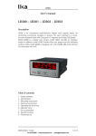
LD25x User's manual LD250 – LD251 – LD252 - LD253 Description LD25x is a SSI display for connecting single-turn or multi-turn SSI encoders. The user's interface is a multi-function keyboard fitted with 3 keys and a 7-segment and 6-digit LED display. Model LD250 is a SSI display only version; model LD251 provides an analogue output in addition; model LD252 further offers two presets and two switching outputs; finally model LD253 is equipped with a RS-232/RS-485 serial interface for connection with a PC. Table of contents 1 - Safety summary 2 - Identification 3 - Mounting instructions 4 - Electrical connections 5 - Operating the front keys 6 - Operator menu 7 - Setup procedure 8 - Hints for application 9 - Special functions 10 - Parameters list MAN LD25x E 1.0.odt PH SYSTEMS - www.phsystems.be - [email protected] 1 of 42 LD25x 1 Safety summary 1.1 Safety • • • • • • • Always adhere to the professional safety and accident prevention regulations applicable to your country during device installation and operation; installation and maintenance operations have to be carried out by qualified personnel only, with power supply disconnected and stationary mechanical parts; device must be used only for the purpose appropriate to its design: use for purposes other than those for which it has been designed could result in serious personal and/or the environment damage; high current, voltage and moving mechanical parts can cause serious or fatal injury; warning ! Do not use in explosive or flammable areas; failure to comply with these precautions or with specific warnings elsewhere in this manual violates safety standards of design, manufacture, and intended use of the equipment; Lika Electronic s.r.l. assumes no liability for the customer's failure to comply with these requirements. 1.2 Electrical safety • • • Turn OFF power supply before connecting the device; connect according to explanation in section ”4 - Electrical connections”; in compliance with 2004/108/EC norm on electromagnetic compatibility, following precautions must be taken: - before handling and installing the equipment, discharge electrical charge from your body and tools which may come in touch with the device; - power supply must be stabilized without noise; install EMC filters on device power supply if needed; - always use shielded cables (twisted pair cables whenever possible); - avoid cables runs longer than necessary; - avoid running the signal cable near high voltage power cables; - mount the device as far as possible from any capacitive or inductive noise source; shield the device from noise source if needed; - minimize noise by connecting the unit to ground (GND). Make sure that ground (GND) is not affected by noise. The connection point to ground can be situated both on the device side and on user’s side. The best solution to minimize the interference must be carried out by the user. 1.3 Mechanical safety • • • • • Install the device following strictly the information in the section “3 Mounting instructions”; do not disassemble the unit; do not tool the unit; delicate electronic equipment: handle with care; do not subject the device and the shaft to knocks or shocks; respect the environmental characteristics of the device. MAN LD25x E 1.0.odt Safety summary PH SYSTEMS - www.phsystems.be - [email protected] 2 of 42 LD25x 2 Identification Device can be identified through the ordering code and the serial number printed on the label applied to its body. Information is listed in the delivery document too. Please always quote the ordering code and the serial number when reaching Lika Electronic s.r.l. for purchasing spare parts or needing assistance. For any information on the technical characteristics of the product, refer to the technical catalog. 3 Mounting instructions WARNING Mount the unit with power supply disconnected. Mount the display into the provided cut-out (approx. 91 x 44 mm) without panel clips. Install panel clips on the display housing and screw until fixed. 110,0 (4.331’’) 91,0 (3.583) 48,0 (1.890) 10,0 (.394) 44,0 (1.732) 8,0 (.315) 96,0 (3.780’’) 9,0 (.345) 129,0 (5.079) 140,5 (5.531) Panel cut out: 91 x 44 mm (3.583 x 1.732’’) MAN LD25x E 1.0.odt Mounting instructions PH SYSTEMS - www.phsystems.be - [email protected] 3 of 42 LD25x 4 Electrical connections WARNING Turn OFF the power supply before connecting the device. LD250 Display unit only 6 7 8 9 10 Input A Input B Input C (Reset) GND +24 VDC OUT GND analogue +/- 10 V analogue DAT DAT 4 1 2 3 4 5 6 7 8 9 10 Input C (Reset) +24 VDC OUT COM+ OUT 1 GND 5 6 7 Input B DAT 4 1 2 3 4 Input A (transm.) Input B PE Input A DAT 2 3 PE TxD / B (-) 8 9 10 GND RxD / A (+) +24 VDC OUT GND Input C (Reset) GND MAN LD25x E 1.0.odt 17-30 VCD IN GND 17-30 VCD IN 1 OUT 2 GND GND PE 17-30 VCD IN CLK 3 0/4-20 mA analogue GND CLK 2 CLK LD253 Display unit with serial interface 1 CLK LD252 Display unit with 2 presets and transistor outputs 0 VAC 5 115 VAC 4 0 VAC 3 0 VAC 2 230VAC 1 115 VAC 4 115 VAC 3 GND DAT 2 230VAC DAT 1 230VAC CLK LD251 Display unit with analogue output CLK All connections are as shown below, except for terminals 8, 9 and 10 which are not connected. Electrical connections PH SYSTEMS - www.phsystems.be - [email protected] 4 of 42 LD25x 4.1 Power supply The unit accepts DC power supply from 17 V to 30 V when using terminals 1 and 2. The consumption depends on the level of the supply voltage (typically 130mA at 30V or 190mA at 17V, plus current taken from aux. output). For AC supply the terminals 0 VAC, 115 VAC or 230 VAC can be used. The total AC power is 7.5 VA. The pictures in the previous page show a dotted line for grounding to PE. This connection is not really necessary, neither for safety nor for EMC. However, for specific applications, it may be useful to ground the common potential of all signal lines. NOTE When using this earthing option, please note that: 1. all terminals and potentials marked “GND“ will be earthed; 2. you should avoid multiple earthing, e.g. when you use a DC power supply where the Minus is already connected to earth etc. 4.2 Aux. voltage output Terminal 7 provides a 24 VDC / 120 mA max. auxiliary output for supply of sensors and encoders. 4.3 Control inputs A, B and C In LD253 model input A is used to activate a serial transmission (rising edge, see section “7.5.2 Printer-Mode” on page 26). Input B is not used. Input C operates as a Set / Reset input (static function, active "HIGH", see section “8.3 Scaling of the display” on page 29). In the basic setup menu, the inputs can be configured to PNP (signal must switch to +) or to NPN (signal must switch to -). This configuration is valid for all three inputs at the same time. The factory setting is always PNP. NOTE 1. When NPN setting is used, please be aware that open NPN inputs will always represent a logical HIGH state. Consequently, Input C has to be connected to GND externally to allow normal operation. If unconnected, the unit would be kept in a continuous Reset state. In model LD253, also Input A must be connected to GND and opening this connection will generate a rising edge to start a serial transmission. 2. When you use 2-wire NAMUR type sensors, please select NPN, connect the negative wire of the sensor to GND and the positive wire to the corresponding input. MAN LD25x E 1.0.odt Electrical connections PH SYSTEMS - www.phsystems.be - [email protected] 5 of 42 LD25x Typical input circuit of control input: PNP NPN +24V int. +24V int. 4,7k Input Input 4,7k GND GND GND The minimum pulse duration on the Reset input (C) must be 5 msec. 4.4 Adjustable analogue output (LD251 model only) A voltage output is available, operating in a range of 0 ... +10 V or –10 V ... +10 V according to setting. At the same time, a current output 0/4 – 20 mA is available. Both outputs refer to the GND potential and the polarity changes with the sign in the display. The outputs are proportional to the display value and provide a 14-bit resolution. The maximum current for the voltage output is 2 mA and the load on the current output can vary between 0 and max. 300 ohms. The response time of the analogue output at each change of the encoder position is approx. 7 msec. 4.5 Optocoupler (transistor) outputs (LD252 model only) Outputs provide programmable switching characteristics and are potential-free. Please connect terminal 8 (COM+) to the positive potential of the voltage you want to switch (range 5V....35V). You must not exceed the maximum output current of 150 mA. If you switch inductive loads, please provide filtering of the coil by means of an external diode. The optocoupler outputs provide a response time of approx. 5 msec with resistive load. Preset 2 Opto Preset 1 Opto (8) Com+ (5 ... 35 V) (9) Output 1 (max. 150 mA) (10) Output 2 (max. 150 mA) Electrical connections 6 of 42 33 R 33 R MAN LD25x E 1.0.odt PH SYSTEMS - www.phsystems.be - [email protected] LD25x 4.6 Serial RS-232 / RS-485 interface (LD253 model only) Ex factory the unit is set to RS-232 communication. This setting can be changed to RS-485 (2-wire) by means of an internal DIL switch. To access the DIL switch, you must remove the screw terminal connectors and the back panel. Then pull the board to the rear to remove the PCB from its housing. ON DIP DIL-Switch Removal of the back panel Location of the DIL switch RS-232 RS-485 ON 10 9 8 TxD RxD GND ON 10 9 8 B (-) A (+) GND WARNING 1. Never set DIL switch positions 1 and 2 or DIL switch positions 3 and 4 to ON at the same time! 2. After setting the switch, shift the print carefully back to its housing, in order to avoid damaging the front pins for connection with the front keypad plate. Connection of the RS-232 interface Connection of the RS-485 interface MAN LD25x E 1.0.odt Electrical connections PH SYSTEMS - www.phsystems.be - [email protected] 7 of 42 LD25x 5 Operating the front keys For setup and other operations the unit is fitted with three front keys which will be denominated as follows in the next pages: ENTER (Input) SET (Setting) CMD (Command) The functions of the keys are depending on the actual operating state of the unit. The following three operating states apply: • Normal display state (see section “5.1 Normal display state” on page 8) • Setup state (see section “5.2 Selection and setting of parameters” on page 9) - Basic setup (see section “7.1 Basic settings” on page 14) - Operational parameters setup (see section “7.2 Operational parameters” on page 16) • Teach operation (see section “5.3 Teach operation” on page 10) 5.1 Normal display state NOTE You can only change over to other operation states while the unit is in the normal display state. Change over to Key operation Basic setup Keep ENTER and SET down simultaneously for 3 seconds Operational parameter setup Keep ENTER down for 3 seconds Teach operation Keep CMD down for 3 seconds The CMD key is only used to execute the Teach procedure with linearization. For more details please refer to sections “9.1 Linearization“ and “9.2 Manual input or „teaching“ of the interpolation points” on page 35. MAN LD25x E 1.0.odt Operating the front keys PH SYSTEMS - www.phsystems.be - [email protected] 8 of 42 LD25x 5.2 Selection and setting of parameters 5.2.1 Selecting a parameter The ENTER key will scroll through the menu. The SET key allows to select the corresponding item and change the setting or the numeric value. After this, the selection can be saved by pressing the ENTER key again, which automatically changes over to the next menu item. 5.2.2 Changing parameter settings With numerical entries, at first the lowest digit will blink. When keeping the SET key continuously down, the highlighted digit will scroll in a continuous loop from 0 to 9 and again from 0 to 9; and so on. After releasing the SET key, the actual value will remain and the next digit will be highlighted (blink). This procedure allows setting all digits to the desired values. After the most significant digit has been set, the low order digit will blink again and you can make corrections if necessary. With signed parameters, the high order digit will scroll from “0” to "9" (positive) followed by “-“ and "-1" (negative). 5.2.3 Saving settings To save the actual setting, press the ENTER key, which will also automatically scroll forward the menu. NOTE At any time the unit changes from programming mode to normal display operation, when you keep the ENTER key down again for 3 seconds at least. 5.2.4 Time-out function A “time-out” function will automatically terminate every menu level, when for a break period of 10 seconds no key has been pressed. In this case, all changes which have not been confirmed by ENTER yet would remain unconsidered. MAN LD25x E 1.0.odt Operating the front keys PH SYSTEMS - www.phsystems.be - [email protected] 9 of 42 LD25x 5.3 Teach operation NOTE The time-out function remains disabled during all Teach operations. Key Function ENTER will terminate or abort any Teach operation in progress SET function is fully similar to normal set-up operation CMD will save the display value in the register and change over to the next interpolation point For further details on the Teach procedure see section “9.2 Manual input or „teaching“ of the interpolation points” on page 37. 5.4 Setting all registers to “Default“ values At any time you can return all settings to the factory default values. WARNING This action will reset all parameters to factory default values and your own settings will be lost. You will have to repeat your individual setup procedure. Factory default values are shown in the subsequent parameter tables (see section “Parameters list” on page 39). To reset the unit to default values: • switch power off; • press the ENTER key on the front; • keep ENTER down while you power up again. MAN LD25x E 1.0.odt Operating the front keys PH SYSTEMS - www.phsystems.be - [email protected] 10 of 42 LD25x 5.5 Code locking of the keypad When the code locking of the keypad has been switched on (see on page 15), any key access first results as follows: -----To access the menu you must press the following key sequence: within 10 seconds, otherwise the unit will automatically return to the normal display mode. MAN LD25x E 1.0.odt Operating the front keys PH SYSTEMS - www.phsystems.be - [email protected] 11 of 42 LD25x 6 Operator menu The menu provides one section with “Basic Parameters” (see section “7.1 Basic settings” on page 14)and another section with “Operational Parameters” (see section “7.2 Operational parameters” on page 16). On the display you will only find those parameters which have been enabled by basic settings. E.g. when the Linearisation function has been disabled in the basic set-up, the associated linearization parameters will also not appear in the parameter menu. All parameters, as good as possible, are designated by text fragments. Even though the possibilities of forming texts are very limited with a 7-segment display, this method has proved to be most suitable for simplification of the programming procedure. The subsequent table shows the general structure of the menu. Detailed descriptions of all parameters will follow in section “7 - Setup procedure“ on page 14. 6.1 Overview of basic parameters LD250 LD251 LD252 LD253 SSI-Mode SSI-Mode SSI-Mode SSI-Mode SSI-Bits SSI-Bits SSI-Bits SSI-Bits SSI-Format SSI-Format SSI-Format SSI-Format SSI-Baud Rate SSI-Baud Rate SSI-Baud Rate SSI-Baud Rate SSI-Test SSI-Test SSI-Test SSI-Test Characteristics Characteristics Characteristics Characteristics Brightness Brightness Brightness Brightness Code Code Code Code Linearization mode Linearization mode Linearization mode Linearization mode Analogue characteristics Preselection mode 1 Serial unit number Analogue offset Preselection mode 2 Serial format Analogue gain Hysteresis 1 Serial baud rate Hysteresis 2 MAN LD25x E 1.0.odt Operator menu PH SYSTEMS - www.phsystems.be - [email protected] 12 of 42 LD25x 6.2 Overview of operational parameters LD250 M-Factor D-Factor P-Factor Decimal point Display Hi_Bit (MSB) Lo_Bit (LSB) Direction Error Error_Polarity Round Loop Time Reset Zero Position LD251 M-Factor D-Factor P-Factor Decimal point Display Hi_Bit (MSB) Lo_Bit (LSB) Direction Error Error_Polarity Round Loop Time Reset Zero Position LD252 Preselection 1 Preselection 2 M-Factor D-Factor P-Factor Decimal point Display Hi_Bit (MSB) Lo_Bit (LSB) Direction Error Error_Polarity Round Loop Time Reset Zero Position Analogue Begin Analogue End P01_X * P01_Y* ... P16_X * P16_Y * P01_X * P01_Y* ... P16_X * P16_Y * LD253 M-Factor D-Factor P-Factor Decimal point Display Hi_Bit (MSB) Lo_Bit (LSB) Direction Error Error_Polarity Round Loop Time Reset Zero Position Ser_Timer Ser_Mode Ser_Value P01_X * P01_Y* ... P16_X * P16_Y * P01_X * P01_Y* ... P16_X * P16_Y * * This only appears if the linearization function has been enabled in the Basic menu. MAN LD25x E 1.0.odt Operator menu PH SYSTEMS - www.phsystems.be - [email protected] 13 of 42 LD25x 7 Setup procedure For better understanding the following sections “7.1 Basic settings” and “7.2 Operational parameters” explain settings related to the display only model (LD250). Model-specific settings for analogue output model (LD251), Preselections model (LD252) and Serial Link model (LD253) will be explained separately under sections from “7.3 Model LD251: additional settings for the analogue output“ to “7.5 Model LD253: additional settings for the serial interface“. 7.1 Basic settings Customarily these settings have to be carried out one time only upon the very first use of the unit. The basic setup selects the desired operation mode of the unit, the input characteristics PNP/NPN and the desired brightness of the LED display. NOTE To access the Basic Setup press the ENTER and SET keys simultaneously for at least 3 seconds. Menu Setting range modE bitS SSI-Mode Setting of Master mode or Slave mode. For details see section “8.1 Master and Slave Operation“ on page 27. SSI-Bits Bit length of the SSI string. For more details see section “8.2 Evaluation of encoder bits“ on page 28. MASte mASte SLA 08 32 bin ... 25 ... bin Form SSI-Format Setting of the SSI code (Binary or Gray). bAUd SSI-Baud Rate 0.1 … 1000.9 kHz SSI Test SSI Self test functions. For more details see section “8.5 Testing functions” on page 34. Characteristics * Switching characteristics of the Reset input. Cd tESt ChAr NPN, switch to “-“ * PNP, switch to “+“ briGht * Brightness Brightness of the 7-segment LED display. Default GrAy 100.0 kHz 11 etc. PnP nPn PnP 20%, 40%, 60%, 80%, 100% Please follow the hints given in section “4.3 Control inputs A, B and C” on page 5 carefully. MAN LD25x E 1.0.odt Setup procedure PH SYSTEMS - www.phsystems.be - [email protected] 14 of 42 100% LD25x Menu Setting range Keypad protection code (for more details see section “5.5 Code locking of the keypad” on page 11). CodE Keypad enabled continuously. Keypad locked for any access. LinEAr Keypad locked, except for access to preselections 1 and 2 (LD252 only, see section “7.4 Model LD252: additional settings for preselections and switching outputs” on page 21). Linearization mode * For details please refer to sections “9.1 Linearization“ and “9.2 Manual input or „teaching“ of the interpolation points“ on page 35. The linearization is switched off. * Linearization settings for the positive range only (negative values will appear as a mirror). Linearization over the full numeric range. * Default no no All P_frEE no no 1-qUA 4-qUA If “no” is set next to this item, the menu will not display any further linearization parameter. MAN LD25x E 1.0.odt Setup procedure PH SYSTEMS - www.phsystems.be - [email protected] 15 of 42 LD25x 7.2 Operational parameters Menu m FAc d FAc p FAc dPoiA diSPLA Hi bit Lo bit Setting Range Default -9.999 … 9.999 1.000 0.001 … 9.999 1.000 -199999 … 999999 0 Decimal Point Setting according to the decimal formats shown in the display. 000000 00000.0 ... 0.00000 00000.0 Display Display mode of the unit: norm: regular scaling of the display; 359.59: angular display format 359° 59' with use of the “Round-Loop” function. For more details see section “8.4.2 “Round-Loop” function” on page 32. norm 359.59 Norm 1 … 32 25 1 … 31 1 M-Factor * Multiplying factor for the SSI value (after consideration of possible bit blanking). D-Factor * Dividing factor for the SSI value (after consideration of possible bit blanking). P-Factor * This signed value will be added to the SSI result (after consideration of possible bit blanking). Hi Bit ** “Bit Blanking” function: defines the highest bit for evaluation. To evaluate all encoder bits this parameter has to be set to the total number of bits according to setting. For more details see section “8.2 Evaluation of encoder bits” on page 28. Lo Bit ** “Bit Blanking” function: defines the lowest bit for evaluation. To evaluate all encoder bits this parameter has to be set to "01". For more details see section “8.2 Evaluation of encoder bits” on page 28. * Scaling details are explained in section “8.3 Scaling of the display” on page 29. ** For more details about “Bit Blanking” function see section “8.2 Evaluation of encoder bits” on page 28. MAN LD25x E 1.0.odt Setup procedure PH SYSTEMS - www.phsystems.be - [email protected] 16 of 42 LD25x Menu Setting Range dir Direction Parameter to negate the SSI value, resulting in a reversal of the direction of the encoder count. riGht: increasing values with forward motion. LEFt: decreasing values with forward motion. Error (please refer to section “8.6 Error messages” on page 34). Defines the control of presence of an encoder and the location of the error bit in case of error. 00: No error bit available 0 ... 32 0 Control of presence of an encoder is off 01: No error bit available Control of presence of an encoder is on >01: Location of the error bit Control of presence of an encoder is on Error-Polarity * Defines the polarity of the error bit in case of error. 0 0 1 0: Error Bit is Low in case of error 1: Error bit is High in case of error When an error occurs, Err-b message is invoked to appear on the display (see section “8.6 Error messages” on page 34). The same function can also be used to monitor the Power Failure Bit of an encoder (mostly called “PFB“). RiGht riGht LEFt Error ErrorP r-LooP Round-Loop Defines the number of encoder steps per revolution when using the “Round-Loop” function (for further information see section “8.4.2 “Round-Loop” function” on page 32). 0: timE Default 0 ... 999999 0 0.000 ... 1.009 sec 0.01 sec Normal display of the encoder data, no “Round-Loop” function. Number of steps per “Round-Loop” cycle. >0: Time Sets the update cycle of the display (and of the analogue output or the switching outputs where applicable). The fastest possible update time is 3 msec. or the time period corresponding to one telegram with 4 pause clocks. With “Slave” operation the next update will occur when the unit synchronizes again to the Master pause following to the expiration of the update time. *) Please observe that parameter p FAc will cause an additional displacement of the zero position. MAN LD25x E 1.0.odt Setup procedure PH SYSTEMS - www.phsystems.be - [email protected] 17 of 42 LD25x Menu Setting Range FE rES 0-PoS P01_X P01_Y P16_X P16_Y Reset A Reset command is available to store the actual SSI position to next register 0-PoS. As a result, the display value will become zero at the actual encoder position and all further operation will refer to this new datum point. The zero position remains memorized also after power-down. no: Reset function disabled Front: Reset operation performed by means of the front SET key E_tErn: Reset operation performed by means of the remote Reset input FR u E: Reset operation performed by means of both key and remote input Zero Position * Defines the zero position of the display. When you set this parameter to e.g. "1024", the unit will display zero when the encoder position is 1024. 0-PoS can be set directly via keypad or by means of an external Reset command. Linearization point 1_X ** X value of the first interpolation point. Linearization point 1_Y ** Y value of the first interpolation point. … Linearization point 16_X ** X value of the 16. interpolation point. Linearization point 16_Y ** Y value of the 16. interpolation point. No Front E_tErn Fr u E Default no -199999 ... 999999 -199999 ... 999999 -199999 ... 999999 -199999 ... 999999 -199999 ... 999999 *) Please observe that parameter p FAc will cause an additional displacement of the zero position. **) Parameters P01_X to P16_Y appear only when the linearization has been enabled in the basic menu. For more details about linearization please refer to section “9.1 Linearization“ on page 35. MAN LD25x E 1.0.odt Setup procedure PH SYSTEMS - www.phsystems.be - [email protected] 18 of 42 0 999999 999999 999999 999999 LD25x 7.3 Model LD251: additional settings for the analogue output The Basic menu provides the following additional settings: Menu Setting Range A-ChAr Analogue characteristics Select one of the following options: +/-10 V (bipolar) 0-10 V (positive output only) 4-20 mA current output 0-20 mA current output OFFSEt GAin Default -0_10 -10_10 0_10 4_20 0_20 With setting +/-10 Volts the polarity of the output voltage will follow the sign in the display. Analogue Offset Set this parameter to 0 when you expect your analogue signal to start with 0 V (or 0 mA / 4 mA respectively). When another zero definition is -9,999 ... +9,999 desired it can be set via this parameter. Setting of e.g. “5.000” will already produce 5 volts with the output in zero state. Analogue Gain It is meant to set the analogue output swing. Setting 10.00 will allow full swing of 10 V or 20 00,00 ... 99,99 mA, setting 8.00 will reduce the swing to 8 V or 16 mA. 0 10 The following Operational parameters provide scaling of the analogue output: Menu AnAbEG AnAEnd Analogue-Begin Start value of the analogue conversion range. Analogue-End End value of the analogue conversion range. Setting Range -199999 ... 999999 -199999 ... 999999 By means of the two above parameters any window of the whole display range can be mapped onto the analogue output. MAN LD25x E 1.0.odt Setup procedure PH SYSTEMS - www.phsystems.be - [email protected] 19 of 42 Default 0 10000 LD25x The subsequent example shows how to convert the display range from 1400 to 2000 into an analogue signal of 2 - 10 volts. Volts Analogue Output 10 8 6 4 2 SSI Display Value 1000 2000 3000 4000 A-ChAr = 0 - 10 V AnAbEG = 1400 OFFSEt = 2.000 AnAEnd = 2000 GAin 5000 = 8.00 NOTE All settings refer to the scaled values which are shown in the display of the unit and not to the original SSI encoder data. MAN LD25x E 1.0.odt Setup procedure PH SYSTEMS - www.phsystems.be - [email protected] 20 of 42 LD25x 7.4 Model LD252: additional settings for preselections and switching outputs The basic setup menu provides the following additional parameters: Menu Default CHAr 1 __r GE Switching characteristics of output 1 __r GE __r LE _n_ GE Greater/Equal: output to switch statically ”ON” when display value ≥ preselection 1. Lower/Equal: output to switch statically ”ON” when display value ≤ preselection 1. Greater/Equal: output to switch dynamically ”ON” when display value ≥ preselection 1. (timed pulse output *) Lower/Equal: output to switch dynamically ”ON” when display value ≤ preselection 1. (timed pulse output *) Switching characteristics of output 2 _n_ LE CHAr 2 __r __r _n_ _n_ __r GE LE GE LE 1-2 _n_ 1-2 HYSt 1 HYSt 2 CHAr See CHAr See CHAr See CHAr See __r GE 1, referred to preselection 2. 1, referred to preselection 2. 1, referred to preselection 2. 1, referred to preselection 2. Output switches statically ON when display value ≥ Preselection 1 – Preselection 2 **. Output switches dynamically ON when display value ≥ Preselection 1 – Preselection 2 **. Hysteresis 1: adjustable hysteresis for output 1. Setting range 0 ... 99999 display units. Hysteresis 2: adjustable hysteresis for output 2. Setting range 0 ... 99999 display units. 0 0 * Timed output pulses have a fixed duration of 500 msec (factory adjustable only). ** Trailing Preset to generate an anticipation signal with a fixed distance to the main signal. MAN LD25x E 1.0.odt Setup procedure PH SYSTEMS - www.phsystems.be - [email protected] 21 of 42 LD25x The following operational parameters provide setting of the switching thresholds: Menu PrES_1 PrES_2 Setting Range -199999 ... 999999 -199999 ... 999999 Preselection 1 Preselection 2 The working direction of the Hysteresis depends on the setting of the switching characteristics. With settings „GE“ or „LE“ respectively, the following switch points will result: Display Value Preselection Hysteresis GE=Greater/Equal Hysteresis effect with "Greater / Equal" Hysteresis Preselection Display Value LE=Lower/Equal Hysteresis effect with "Lower / Equal" It is possible to check up on the actual switching state of the outputs at any time. For this, just tap on the ENTER key shortly. The display will then show for the next two seconds one of the following information: Display Meaning 1_2oFF 1_2on 1 on 2on Both outputs are actually off. Both outputs are actually on. Output 1 is on. Output 2 is off. Output 1 is off. Output 2 is on. MAN LD25x E 1.0.odt Setup procedure PH SYSTEMS - www.phsystems.be - [email protected] 22 of 42 Default 10000 5000 LD25x 7.5 Model LD253: additional settings for the serial interface The basic setup menu contains the main parameters for configuration of the serial interface. Menu S-Un it S-Forn Serial Unit Number You can assign any address number between 11 and 99 to your unit. The address must not contain a “0“ because such numbers are reserved for collective addressing of several units. Default 0 ... 99 11 7 E 1 Serial data format The first character indicates the number of Data Bits. The second character specifies the Parity Bit (“even” or “odd” or “none”). The third character indicates the number of Stop Bits. S-bAUd Setting Range 7 E 1 7 E 2 7 0 1 7 0 2 7 no 1 7 no 2 8 E 1 8 0 1 8 no 1 8 no 2 9600 Baud rate The following baud rates can be selected. MAN LD25x E 1.0.odt 9600 4800 2400 1200 600 19200 38400 Setup procedure PH SYSTEMS - www.phsystems.be - [email protected] 23 of 42 LD25x The following operational parameters provide setting of the communication profile: Menu S-tim Serial Timer Setting 0,000 allows manual activation of a serial data transmission at any time. All other settings specify the cycle time for automatic transmission (provided the Smod item is set to "Printer-mode" (see the next item and on page 26). Setting Range Default 0,000 0,010 sec … 9,999 sec 0,100 sec Between two transmission cycles the unit will allow a pause depending on the baud rate. The minimum cycle times for timer transmissions are shown in the table. Baud Rate 600 1200 2400 4800 9600 19200 38400 S-mod S-CodE Minimum Cycle Time [msec] 384 192 96 48 24 12 6 PC Serial Mode Operation according to communication profile (see section “7.5.1 PC-Mode“ on page 25). Transmission of string type 1 (see section “7.5.2 Printer-Mode” on page 26). Transmission of string type 2 (see section “7.5.2 Printer-Mode“ on page 26). Serial Register-Code PC Print1 Print2 Specifies the register code of the data to be transmitted. The most important register codes are: Register S-Code Original 111 SSI value ASCII ;1 SSI value 113 ;3 Display value 101 :1 MAN LD25x E 1.0.odt Description Direct encoder data Encoder data after Bit Blanking Value with full scaling as it appears in the display Setup procedure PH SYSTEMS - www.phsystems.be - [email protected] 100 ... 120 24 of 42 101 LD25x 7.5.1 PC-Mode Communication with PC mode allows free readout of all parameters and registers of the unit. The subsequent example shows the details of communication for serial readout of the actual display value. This is the general format of a serial request string: EOT AD1 AD2 C1 C2 EOT = Control character (Hex 04) AD1 = Unit address, High Byte AD2 = Unit address, Low Byte C1 = Register code, High Byte C2 = Register code, Low Byte ENQ = Control character (Hex 05) ENQ Example Request for the actual display value from unit number 11. ASCII-Code Hexadecimal Binary EOT 04 0000 0100 1 31 0011 0001 1 31 0011 0001 Upon correct request the unit will respond as shown on the right. Leading zeros will be suppressed. BCC represents a block check character generated from an Exclusive-OR of all characters from C1 through ETX (inclusively). : 3A 0011 1010 1 31 0011 0001 STX C1 C2 x x x x x x x ETX STX = Control character (Hex 02) C1 = Register code, High Byte C2 = Register code, Low Byte x x x x x = Register data ETX = Control character (Hex 03) BCC = Block check character ENQ 05 0000 0101 BCC With incorrect request strings, the unit only responds STX C1 C2 EOT or just NAK. Provided the actual display value of the unit is "-180" for instance, the full response of the unit will be as shown below: ASCII Hex Binary STX 02 0000 0010 : 3A 0011 1010 1 31 0011 0001 2D 0010 1101 1 31 0011 0001 8 38 0011 1000 0 30 0011 0000 ETX 03 0000 0011 Again BCC represents the block check character formed from the Exclusive-OR of all characters from C1 through ETX. MAN LD25x E 1.0.odt Setup procedure PH SYSTEMS - www.phsystems.be - [email protected] 25 of 42 BCC 1C 0001 1100 LD25x 7.5.2 Printer-Mode The Printer mode allows cyclic or manual activation of transmissions of the specified register data. The corresponding register can be specified by means of parameter S-CodE. Another parameter called S-mod allows the selection between two different string types: „S-mod“ „Print1“ Transmission string type Space Sign Data +/„Print2“ Sign X X X X X X Data +/- X X X X X X Line feed LF Carriage return CR The mode of activation of serial transmissions can be determined as follows: Cyclic (timed) transmissions Set the S-tim item (see on page 23) to any value ≥ 0.010 sec. Select the desired string type next to parameter Smod. After exiting the menu the timed transmissions will start automatically. Manual activation of Set the S-tim item (see on page 23) to 0.000. transmissions Select the desired string type by means of parameter S-mod. After exiting the menu a transmission can be activated at any time either by shortly pressing the ENTER key or by the rising edge of input A. MAN LD25x E 1.0.odt Setup procedure PH SYSTEMS - www.phsystems.be - [email protected] Carriage return CR 26 of 42 LD25x 8 Hints for application 8.1 Master and Slave Operation Set register modE (see section “7.1 Basic settings” on page 14) to position “Master” when the unit should generate the clock signal for the encoder. In this case the clock terminals (CLK) are configured as clock outputs. SSI Encoder (+24V) Screen SSI Indicator (optional) 7 (+24V out) Clock- CLK CLK Clock+ DataData+ DAT GND 6 (GND) DAT SSI Indicator with Master Operation When your encoder receives its clock from another device already and the unit should only “listen” to the communication, then set register modE to “Slave”. In this case, both clock terminals (CLK) are configured as inputs. SSI Indicator Remote Master Screen Data+ Data- Clock- + Clock+ ClockClock+ CLK CLK Data- DAT Data+ DAT 6 (GND) - SSI Encoder SSI Indicator with Slave Operation Set registers bitS, Form and bAUd (section “7.1 Basic settings” on page 14) according to the encoder you use. You are free to set any baud rate in a range from 0.1 kHz to 1000.0 kHz. However, for technical reasons, in the upper frequency range the unit in “Master” mode can only generate one of the following baud rates accurately: 1000,0 kHz 615,0 kHz 444,0 kHz 347,0 kHz 285,0 kHz 888,0 kHz 571,0 kHz 421,0 kHz 333,0 kHz 275,0 kHz MAN LD25x E 1.0.odt 800,0 kHz 533,0 kHz 400,0 kHz 320,0 kHz 266,0 kHz 727,0 kHz 500,0 kHz 380,0 kHz 307,0 kHz 258,0 kHz Hints for application PH SYSTEMS - www.phsystems.be - [email protected] 666,0 kHz 470,0 kHz 363,0 kHz 296,0 kHz 250,0 kHz 27 of 42 LD25x With Master operation, therefore other settings will result in generation of the next upper or lower value according to above list. With all settings <250.0 kHz the error between set rate and generated rate becomes negligible. It is mandatory to set the baud rate also with “Slave” operation. In this case, however, the setting is only used to determine the pause time for correct synchronization (pause is detected after 4 clock cycles). The unit automatically synchronizes with every remote clock signal within the specified baud rate range. 8.2 Evaluation of encoder bits This section is meant to explain the correlation between the basic parameter bitS (section “7.1 Basic settings” on page 14) and the operational parameters Hi bit and Lo bit (see section “7.2 Operational parameters” on page 16). The example below assumes that the encoder has a 16-bit resolution. NOTE • Unused bits may be blanked out according to individual need. • Whenever the number of bits (clock cycles) requested from the SSI Master is higher than the real number of encoder bits, all excessive bits must be blanked by corresponding setting of parameters Hi bit and Lo bit (see section “7.2 Operational parameters” on page 16). 8.2.1 Basic settings In general, parameter bitS will always be set according to the real resolution of the encoder (i.e. bitS = 16 with a 16-bit encoder). In this normal case the SSI telegram will not contain any excessive bits. With some applications (e.g. with Slave operation) however it may happen that the Master transmits more clock cycles than the number of encoder bits (e.g. 21 clocks with a 16-bit encoder). In such a case the master would always request 21 bits from the encoder, where the encoder responds with 16 usable bits only, followed by 5 waste bits. These 5 excessive bits must be blanked. All standard SSI telegrams start with the most significant bit (MSB) and close with the least significant bit (LSB). Unusable waste bits (X) will follow at the end of the string. To blank these bits out, in our example we would have to set Hi bit to 21 and Lo bit to 6 for proper evaluation of the encoder information. Hi Bit Lo Bit Requested bits (clocks) 21 2 0 1 9 1 8 1 7 1 6 1 5 1 4 1 3 1 2 1 1 1 0 9 8 7 6 5 4 3 2 1 Usable bits (encoder) 16 1 5 1 4 1 3 1 2 1 1 1 0 9 8 7 6 5 4 3 2 1 X X X X X MAN LD25x E 1.0.odt Hints for application PH SYSTEMS - www.phsystems.be - [email protected] 28 of 42 LD25x 8.3 Scaling of the display Under consideration of the scaling parameters which have been described previously, the final display value of the unit will result from: DISPLAY = { [Encoder SSI Data] - [0-Position] } x M-Factor D-Factor +/- P-Factor NOTE • Encoder SSI data are always positive only. When also negative values should be indicated, this can be achieved by corresponding setting of the parameters 0-PoS or P FAc (see section “7.2 Operational parameters” on page 16). • The LED display provides 6 decades. For this reason all parameter settings (including 0-PoS) are also limited to a maximum range of 6 decades. SSI encoders having a resolution of more than 19 bits will however generate SSI data with more than 6 decades. In such a case it can become difficult to set the 0-PoS value and the other scaling parameters while the mechanical encoder position is in the overflow zone (the unit would insistently display "overflow"). To avoid this kind of problem with encoders of more than 19 bits, we recommend to use the “Bit Blanking” function and evaluate 19 bits only (see section “8.2 Evaluation of encoder bits” on page 28). • If you intend to use the "Round Loop" function later (see r-LooP parameter in the section “7.2 Operational parameters” on page 16 and section “8.4.2 “Round-Loop” function” on page 32), it is mandatory to blank all unused bits. • Remote Reset/Set commands via keyboard or external input will overwrite the current value of parameter 0-PoS by the actual SSI position of the encoder. Therefore, in the formula above, the content between the brackets { } will become zero and the unit will display the same value as set to parameter P FAc. This scaling is also automatically stored to the Flash Prom for full data retention in power-down state. MAN LD25x E 1.0.odt Hints for application PH SYSTEMS - www.phsystems.be - [email protected] 29 of 42 LD25x 8.4 Basic modes of operation 8.4.1 Normal SSI display Normal operation provides calculation of the display value from the SSI encoder data and the settings of the scaling factors. Negative values can be achieved by corresponding setting of the zero position (0-Pos item) or by inversion of the direction bit (dir item). To set the unit up without problem, it is advisable to use the following sequence of steps: • Set all basic registers according to the encoder type you use, as shown in section “7.1 Basic settings” on page 14. • For better comprehension, use first all initial settings as shown in the list (xxx = according to need). M-Factor D-Factor P-Factor Decimal Point Display Hi bit 1.000 Direction 1.000 Error 0 Error P 000000 Round-Loop 0 Time see sections 8.2 Reset and 8.3 on page : 28 * Lo bit 0-Position * Please evaluate 19 bits only to avoid overflow. : : : : : : : : : : : : 0 xxx xxx 0 xxx no : 0 These settings ensure that the unit displays the pure SSI encoder information at first. • • • Move your encoder now from a “lower” position towards a “higher” position according to your own definition of "low" and "high". When also the display changes from lower to higher values, your own definition of directions matches with the encoder definition. If not, change the setting of “Direction” (dir item) from “0” to “1” now to receive the desired sense of direction (changes after further parameter settings may cause different results) **. Set the desired zero position, either by entering the numeric value to the “0-Position” register (0-Pos item) or by using the Reset function as described previously. Your zero definition will divide the range into a positive and a negative zone. At this time you are free to set all other registers according to your needs. The subsequent drawings show the principle of evaluation with use of a 13-bit single-turn encoder, with the direction bit (dir item) set to either “0” or to “1” and with the zero position register (0-Pos item) set to “1024” **. ** Subject of correct sequence with parameter settings. MAN LD25x E 1.0.odt Hints for application PH SYSTEMS - www.phsystems.be - [email protected] 30 of 42 LD25x 8192 7168 Original encoder signal Encoder 13Bit Direction = 0 0-Position = 1024 Display 1024 0o 45 o 180o 360 o 0-PoS = 1024 degrees Data display with positive counting direction 8192 Original encoder signal Encoder 13Bit Direction = 1 0-Position = 1024 1024 0o 180o 45 o 0-PoS = 1024 360 o degrees Display -7168 Data display with negative counting direction MAN LD25x E 1.0.odt Hints for application PH SYSTEMS - www.phsystems.be - [email protected] 31 of 42 LD25x 8.4.2 “Round-Loop” function This operational mode is often used with rotating round tables or similar applications, where the absolute encoder information is only used for a limited and repeating range of the encoder (as for instance one revolution of the table, which does not necessarily result in one revolution of the encoder shaft). The “Round-Loop” function never uses any negative display value. The “Round-Loop” function allows a programmable number of encoder steps to be assigned to one complete 360º rotation of the table. To avoid miscounting when passing the mechanical overflow of the encoder range, the total encoder resolution should be an integer multiple of the number of steps for one loop. To proceed with setup operation, please first proceed as explained in section “8.4.1 Normal SSI display” on page 30. Then set the “Round-Loop” register (r-LooP item) to the number of steps corresponding to one revolution of the table. You are free to scale the display to any engineering units desired, by setting the scaling factors correspondingly. If you like to scale your display with the angular display format 359º59’, just change the “Display” register (diSPLA item) from “0” to “359,59”. This will also automatically disable the general scaling factors. The subsequent diagram shows the “Round-Loop” function with a 13-bit encoder, assuming that one table revolution corresponds to 2048 encoder steps and the zero position is set to “1024”. 8192 Original encoder signal Encoder 13Bit Direction = 0 0-Position = 1024 r-Loop = 2048 Round-Loop display 2048 1024 180 0 0-PoS = 1024 360 degrees r-LooP = 2048 “Round-Loop” operation with 2048 steps / revolution when using a 13-bit encoder MAN LD25x E 1.0.odt Hints for application PH SYSTEMS - www.phsystems.be - [email protected] 32 of 42 LD25x 8.4.3 Operation with “Zero-Crossing” As a special advantage, the “Round-loop” function mode can be used to bypass the mechanical encoder overflow position, because in this mode the unit continues with steady operation, even while the SSI encoder signal passes the mechanical overflow position from maximum value back to zero. This feature can help to avoid mechanical adjusting of the encoder zero position with many applications, when no other means for the mechanical zero definition is available. As a general rule, the Reset input will be used to define the zero position. The following picture explains the details of this operation. 8192 Original encoder signal Overflow Encoder: 13 Bit Direction = 0 r-LooP = 6000 0-PoS = 3500 Display 3500 0o 360 o 0-PoS = 3500 degrees r-LooP = 6000 Overflow suppression with a 13-bit SSI encoder 8.4.4 Splitting of SSI encoder information into two separate displays The “Bit Blanking” function also allows to distribute one SSI telegram to two different SSI indicator units. As a typical application the figure below shows how to separate the angular information within one turn and the number of turns in a 16 x 16 multi-turn encoder. Master: bits 17 - 32 (number of turns) Multiturn SSI 16 + 16 = 32 Bit Slave: bits 01 - 16 (angular position) Parameters: Bits = 32 HiBit = 32 LoBit = 17 MAN LD25x E 1.0.odt Parameters: Bits = 32 HiBit = 16 LoBit = 01 Hints for application PH SYSTEMS - www.phsystems.be - [email protected] 33 of 42 LD25x 8.5 Testing functions The test menu can be accessed while programming the basic set up, as shown in section “7.1 Basic settings” on page 14, see tESt item. Most of these tests are for factory use only, but the following tests may be useful also to the user: Menu Selection Text Cd 11 Cd 10 Cd iO C__ d__ Cd__ Description Cd (Clock- and data wiring test) When the wiring of clock line and data line is ok, the display shows “Cd 11”. “Cd 10” message means that the clock line is ok but data wires are false (wrong polarity), while "Cd 01" indicates a problem with the clock lines. In “Master” mode, only data lines are subject to this test. Cd (Clock- and data function test) The next test generates clock and data signals and feeds them directly into the rear terminals. Therefore please remove the encoder connection. “Cd iO” informs that clock and data interface are all right. All remaining messages indicate there is a problem with the SSI interface circuit. 8.6 Error messages The unit can detect and display the errors listed below. If you find an error message, please check again the encoder wiring and the settings of all SSIrelevant parameters. Menu Err -0 Err -b Err -t Err -F Err-E1 Err-E2 Description Overflow The selected SSI baud rate is too high. Please set a lower baud rate value. Bit error The error bit or the power failure bit of the encoder (PFB) are set. Time-out error In “Slave” mode, during the last 0.6 seconds (plus wait time setting) the unit did not receive any valid data. Format error In “Slave” mode, a telegram having a too short length has been received. Missing encoder (1) Right after power-up the unit detects that all SSI telegrams are empty (all bits = 1). Missing encoder (2) During normal operation the unit detects that regular SSI telegrams are suddenly followed by empty telegrams (all bits = 1). MAN LD25x E 1.0.odt Hints for application PH SYSTEMS - www.phsystems.be - [email protected] 34 of 42 LD25x 9 Special functions 9.1 Linearization This function allows a non-linear input signal to be converted into a linear representation or vice versa. 16 interpolation points are available, they can be freely arranged over the whole measuring range at any distance. Between two points the unit will interpolate automatically straight lines. It is advisable to set several points into areas with strong bending and to use only a few points in areas with little bending. “Linearisation Mode“ has to be set to either 1-quA or 4-quA (see LinEAr item in section “7.1 Basic settings”) to enable the linearization function (see subsequent drawing). Parameters P01_x to P16_x select 16 x- coordinates, representing the display values which the unit would normally show in the display. With parameters P01_y to P16_y you can specify which values you would like to display instead of the corresponding _x values. This means e.g. that the unit will replace the previous P02_x value by the new P02_y value. NOTE • With respect to the consistency of the linearization, the x- registers have to use continuously increasing values, e.g. the x- registers must conform to the constraint P01_x < P02_x < … < P15_x < P16_x. • Independently of the selected linearization mode, the possible setting range of all registers P01_x, P01_y,…, P16_x, P16_y is always -199999 … 999999. • With measuring values lower than P01_x the display will always show P01_y. • With measuring values higher than P16_x, the display will always show P16_y. y P1(x)= -1000 P1(y)= 900 P16(x)= 1000 P16(y)= 800 x *) y P8(x)= 0 P8(y)= 750 x P16(x)= +1000 P16(y)= - 600 P1(x)= 0 P1(y)= 0 Linearization M ode = 1_quA Linearization M ode = 4_quA * Mirror of positive range MAN LD25x E 1.0.odt Special functions PH SYSTEMS - www.phsystems.be - [email protected] 35 of 42 LD25x EXAMPLE The picture below shows a sluiceway where the gate is controlled by means of a SSI encoder. We would like to display the clearance of the gate "d", but the existing encoder information is proportional to the angular information φ. Display value d = d0 (1-cos φ ) SSI Encoder d φ Display (d) P16_y P15_y P07_y P05_y MAN LD25x E 1.0.odt P16_x P15_x P07_x P05_x SSI Data (φ) P03_x P01_x P03_y P01_y Special functions PH SYSTEMS - www.phsystems.be - [email protected] 36 of 42 LD25x 9.2 Manual input or „teaching“ of the interpolation points Interpolation points to form the linearization curve can be entered one after each other, using the same procedure as for all other numeric parameters. This means you will have to enter all parameters P01_x to P16_x and P01_y to P16_y manually using the keypad. WARNING During manual input of interpolation points the unit will not examine the settings P01_x to P16_x. Therefore the operator is responsible for adherence to the constraint P01_x < P02_x < … < P15_x < P16_x. In most cases it should however be much more convenient to use the Teach function. For this method we have to move the encoder, step by step, from one interpolation point to the next. After each step we enter the desired display value through the keypad. How to use the “Teach” function • Please select the desired range of linearization (see section “7.1 Basic settings”). • Hold down the CMD key for 3 seconds, until the display shows tEACh. Now the unit has switched over to the Teach mode. To start the teach procedure please press again the CMD key within the next 10 seconds. The display will then show P01_X. • With respect to the consistency required for linearization, all parameters from P01_x to P16_ y will be overwritten by suitable initial values first. Initial values for P01_x and P01_y are -199999 and all other values will start with 999999. • Press once more the CMD key to display the actual encoder position. Then move the encoder to the first of the desired interpolation points. • When you read the x-value of your first interpolation point in the display, press CMD key again. This will automatically store the actual display value in the P01_x register. For about 1 second you will read P01_y on the display, followed by the same reading again that has been stored previously. • This display value now can be edited like a regular parameter and you can change it to the desired P01_Y value. • When you read the desired P01_Y value in your display, save it by pressing CMD key again. This will cause the display to automatically scroll to the next interpolation point P02_x. MAN LD25x E 1.0.odt Special functions PH SYSTEMS - www.phsystems.be - [email protected] 37 of 42 • • LD25x Once we have reached and saved the last interpolation points P16_x/y, the routine will restart with P01_x again. You are free to double-check your settings once more or to make corrections. To finish the Teach procedure, keep ENTER key down for about 2 seconds. In the display you will read StOP for a short time and then the unit returns to the normal operation. At the same time all linearization points have been finally saved. NOTE • The unit will examine the constraint valid for the x-values of interpolation points. Every interpolation point must be higher than its preceding point. If this constraint is breached, all 6 decimal points will blink automatically as a warning. Pressing the CMD key will not store the illegal value, but result in an error text E.r.r.-.L.O.. • To exit the teach mode again, you have the following two possibilities: 1. Press the ENTER key for 2 seconds. On the display you will read StOP for a short time and then the unit will switch back to the normal mode. 2. Just do nothing. After 10 seconds the unit will switch back to the normal mode automatically. In both cases the parameters of linearization P01_x to P16_Y will not change. MAN LD25x E 1.0.odt Special functions PH SYSTEMS - www.phsystems.be - [email protected] 38 of 42 LD25x 10 Parameters list 10.1 General Description SSI-Mode SSI-Bits SSI-Format SSI-Baudrate SSI-Test NPN / PNP Brightness Code locking M-Factor D-Factor P-Factor Decimal point Display Hi_Bit MSB Lo_Bit LSB Direction Error bit Error polarity Round-Loop Wait time Reset Zero position Text modE bitS Form bAUd tESt CHAr briGht Code mFAc dFAc PFAc dPoint diSPLA Hi_bit Lo_bit dir Error ErrorP r-looP timE FErES 0-PoS MAN LD25x E 1.0.odt Min. value 0 08 0 0.1 0 0 0 0 -9.999 0.001 -199999 0 0 1 1 0 0 0 0 0.000 0 -199999 Max. value 1 32 1 1000.9 2 1 4 2 +9.999 9.999 +999999 5 1 32 31 1 32 1 999999 1.009 3 +999999 Default value 0 25 0 100.0 0 1 0 0 1.000 1.000 0 0 0 25 1 0 0 0 0 0.010 0 0 Positions Characters 1 2 1 5 1 1 1 1 +/- 4 4 +/- 6 1 1 2 2 1 2 1 6 4 1 +/- 6 Parameters list PH SYSTEMS - www.phsystems.be - [email protected] 0 0 0 1 0 0 0 0 3 3 0 0 0 0 0 0 0 0 0 3 0 0 39 of 42 Serial code 00 01 02 03 04 05 06 07 08 09 10 11 12 13 14 15 16 17 18 19 20 21 LD25x Description Text Min. value Max. value Default value Linear. mode LinEAr 0 2 0 1 0 D2 P01_H -199999 999999 999999 +/-6 0 A0 P01_Y -199999 999999 999999 +/-6 0 A1 P02_H P02_Y P03_H P03_Y P04_H P04_Y P05_H P05_Y P06_H P06_Y P07_H P07_Y P08_H P08_Y P09_H P09_Y P10_H P10_Y P11_H P11_Y P12_H P12_Y P13_H P13_Y P14_H P14_Y P15_H P15_Y P16_H P16_Y -199999 -199999 -199999 -199999 -199999 -199999 -199999 -199999 -199999 -199999 -199999 -199999 -199999 -199999 -199999 -199999 -199999 -199999 -199999 -199999 -199999 -199999 -199999 -199999 -199999 -199999 -199999 -199999 -199999 -199999 999999 999999 999999 999999 999999 999999 999999 999999 999999 999999 999999 999999 999999 999999 999999 999999 999999 999999 999999 999999 999999 999999 999999 999999 999999 999999 999999 999999 999999 999999 999999 999999 999999 999999 999999 999999 999999 999999 999999 999999 999999 999999 999999 999999 999999 999999 999999 999999 999999 999999 999999 999999 999999 999999 999999 999999 999999 999999 999999 999999 +/-6 +/-6 +/-6 +/-6 +/-6 +/-6 +/-6 +/-6 +/-6 +/-6 +/-6 +/-6 +/-6 +/-6 +/-6 +/-6 +/-6 +/-6 +/-6 +/-6 +/-6 +/-6 +/-6 +/-6 +/-6 +/-6 +/-6 +/-6 +/-6 +/-6 0 0 0 0 0 0 0 0 0 0 0 0 0 0 0 0 0 0 0 0 0 0 0 0 0 0 0 0 0 0 A2 A3 A4 A5 A6 A7 A8 A9 B0 B1 B2 B3 B4 B5 B6 B7 B8 B9 C0 C1 C2 C3 C4 C5 C6 C7 C8 C9 D0 D1 Linear. point 1 Linear. point 2 Linear. point 3 Linear. point 4 Linear. point 5 Linear. point 6 Linear. point 7 Linear. point 8 Linear. Point 9 Linear. Point 10 Linear. point 11 Linear. point 12 Linear. point 13 Linear. point 14 Linear. point 15 Linear. point 16 MAN LD25x E 1.0.odt Positions Characters Parameters list PH SYSTEMS - www.phsystems.be - [email protected] 40 of 42 Serial code LD25x 10.2 Analogue output (model LD251) See section “7.3 Model LD251: additional settings for the analogue output” on page 19 Description Analogue mode Offset Gain Analogue begin Analogue end Text A-CHAr OFFSEt GAin AnAbEG AnAEnd Min. value 0 -9,999 00,00 -199999 -199999 Max. value 3 +9,999 99,99 999999 999999 Default value 0 0,000 10,00 0 100000 Positions Characters 1 +/- 4 4 +/- 6 +/- 6 0 3 2 0 0 Serial code 33 34 35 31 32 10.3 Preselections (model LD252) See section “7.4 Model LD252: additional settings for preselections and switching outputs” on page 21 Description Presel. mode 1 Presel. mode 2 Hysteresis 1 Hysteresis 2 Preselection 1 Preselection 2 Text CHAr 1 CHAr 2 HYst1 HYst2 PrES 1 PrES 2 Min. value 0 0 0 0 -199999 -199999 Max. value 3 5 99999 99999 +999999 +999999 Default value 0 0 0 0 10000 5000 Positions Characters 1 1 5 5 +/- 6 +/- 6 0 0 0 0 0 0 Serial code 29 30 36 37 27 28 10.4 Serial interface (model LD253) See section “7.5 Model LD253: additional settings for the serial interface” on page 23 Description Text Serial address Serial format Baud rate Serial timer Serial mode Register-code S-Unit S-Form S-bAUd S-tim S-mod S-CodE MAN LD25x E 1.0.odt Min. value 0 0 0 10 0 100 Max. value 99 9 6 9999 2 120 Default value 11 0 0 100 0 101 Positions Characters 2 1 1 4 1 3 Parameters list PH SYSTEMS - www.phsystems.be - [email protected] 0 0 0 3 0 0 41 of 42 Serial code 90 92 91 38 39 40 Document release 1.0 Description 1st issue Lika Electronic Via S. Lorenzo, 25 - 36010 Carrè (VI) - Italy Tel. +39 0445 806600 Fax +39 0445 806699 Italy: eMail [email protected] - www.lika.it World: eMail [email protected] - www.lika.biz PH SYSTEMS - www.phsystems.be - [email protected]