1
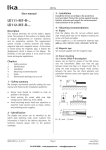
EBOX – SMB5 – SMB2 – SM - MT
1 Safety summary
User manual
EBOX
SMB5, SMB2
SM5, SM2
MT50, MT20
Description
This manual describes products of the EBOX, SMB5,
SMB2, SM and MT series. The purpose of these
sensors is to measure linear or angular
displacements on industrial machines and
automation systems. The measurement system
includes a magnetic tape and a magnetic sensor.
The tape has alternating magnetic north/south poles
are magnetized at a certain distance called the pole
pitch. As the sensor is moved along the magnetic
tape, it detects the displacement and produces an
output signal equivalent to that of an incremental
encoder or a linear scale. The flexibility of the tape
allows it to be used for both linear and angular
applications.
The sensor has to be matched with the appropriated
magnetic tape (see chap. 2.1).
We strongly recommend carefully reading this user
manual and following the following installation
guidelines:
- Sensor head should be installed as close as
possible to your control unit
- Always use shielded cables and twisted if possible
- Avoid running the sensor cable near high voltage
power cables (e.g. drive cables)
- Install EMC filters on sensor power supply if
needed
- Avoid mounting sensor head near capacitive or
inductive noise sources such as relays, motors, and
switching power supplies
Connect according to the supplied pin-out.
2 Identification
The sensor can be identified by the label's data
(ordering code, serial number). This information is
listed in the delivery document. The technical
features of the product can be determined by the
ordering code (see chap. 11 "Ordering code").
2.1 Sensor and tape combinations
Sensor
Tape
SM5
SM2
SMB5
SMB2
MT50
MT20
MT50
MT20
1 2 3
4
0
5
98 6
7
EBOX
SMx-C
Gap
sensor/tape
2.1 mm
1.0 mm
2.1 mm
1.0 mm
3 Installation
SMx-R
Chapters
1 Safety summary
2 Identification
3 Installation
4 Mounting recommendations
5 Output signals
6 Electrical connections
7 Parameters setup
8 Dimensional drawing
9 Maintenance
10 Troubleshooting
11 Ordering code
Rev.1.1
Resolution
max.
5 µm
10 µm
10 µm
10 µm
Install the product according to the protection level
provided.
Protect the system against knocks, friction, solvents,
temperatures under -10°C (14°F) and over +70°C
(+158°F).
Be sure that the system is mounted where hard or
sharp objects (e.g. metal chips) do not come into
contact with the magnetic scale and the bottom of
the sensor head. If these conditions cannot be
avoided provide a wiper or pressurized air.
Pag.9 di 16
PH SYSTEMS - www.phsystems.be - [email protected]
www.lika.it
EBOX – SMB5 – SMB2 – SM - MT
4 Mounting instructions
4.1 Magnetic tape
Total length of the magnetic tape should exceed
measuring length at least 10 mm (0.4") each side.
The magnetic tape has been delivered in a roll and
can be cut to the desired length with any sheet
metal cutting tool.
Make sure that mechanical installation meets the
system's requirements of planarity and parallelism
between sensor and tape. (see fig. 1. and chap. 2.1).
Attention!! The active side of magnetic tape (black
side), however installed, has to face the active part
of magnetic sensor ("scale side").
4.1.1 Mounting with the double-sided adhesive
tape
figure 3
Use this installation for applications in clean
environments with little contamination. For mounting in
highly contaminated places and under the effects of
spray water, use of liquid glue is recommended.
Step by step procedure:
D
5
<3°
6
4
3
2
<1°
1
figure 4
<3°
figure 1
D
figure 2
Rev.1.1
Marker
<3°
Mounting surface (1) must be dry and clean in order
to achieve secure bonding.
- Remove short parts of the protection film (2) from
the adhesive part of the tape (3) and adhere by
pressing the tape firmly on the mounting surface.
- Carefully clean the tape (4).
- Remove short parts of the protection film (6) from
the stainless steel protection tape (5) and adhere by
pressing firmly.
Attention!! For secure bonding, oil , grease,
moisture and dust must be removed without leaving
residues. Gluing should be carried out in dry
environment and at temperatures between 20°C
(60°F) and 30°C (85°F).
When mounting the magnetic tape, please ensure
that the bending radius is not less than 350 mm
(13").
Pag.10 di 16
PH SYSTEMS - www.phsystems.be - [email protected]
www.lika.it
EBOX – SMB5 – SMB2 – SM - MT
Remember that the maximum allowed gap is
between sensor and tape and NOT between sensor
and profile surface.
4.1.2 Mounting with double backed adhesive
tape and screws
4.1.5 Mounting on circular surfaces
figure 5
Carry out the mounting procedure as per chapter
4.1.1 and additionally attach the tape on both ends
only outside the measuring length with screws or
rivets. This is recommended only in contaminated
environments where the tape may peel.
Mounting
procedure
for
circular/angular
applications is same as for linear applications (see
chap. 4.1.1). The resolution of the system depends
on the diameter of the tape.
See fig. 9 for minimum radius of circular
applications.
4.1.3 Mounting in a groove
figure 6
figure 7
Provide a groove on the mounting surface. The tape
can be installed in the groove (fig. 6) and simply
fixed as described in chap. 4.1.1 or completely
covered (fig. 7) with nonmagnetic liquids (e.g.
Loctite liquid aluminum). In this case installation of
the protection tape is not necessary.
4.1.4 Mounting with PS1 profile (accessory)
figure 8
Step by step procedure:
- Place the tape on the mounting surface and
attach according to chap. 4.1.1. The protection
tape should not be mounted in this case.
- Cover the tape with PS1 profile (fig. 8) and make
attachment holes along the profile's groove
without damaging the tape.
- Fix the profile with screws or rivets
Rev.1.1
figure 9
4.2 Sensor mounting
4.2.1 Sensor type R (rectangular)
Sensor can be fixed by means of two M3 screws
over the buttonholes. Make sure that the gap
between sensor and tape is in respect with (fig. 1)
along the total measuring length. Avoid contact
between the parts. You can check planarity and
parallelism between sensor and magnetic tape using
a feeler gauge. The max. allowed gap is listed in
chap. 2.1.
4.2.2 Sensor type C (circular)
(Series SM2-C, SM5-C, SMB2-C, SMB5-C)
The sensor can be fixed in a corresponding
mounting hole by means of the two nuts. Make sure
that the gap between sensor and tape is in respect
with (fig. 1) along the total measuring length.
Observe the correct alignment of the marker on
the tape. Avoid contact between the parts. You can
check planarity and parallelism between sensor and
magnetic tape using a feeler gauge. The max.
allowed gap is listed in chap. 2.1.
Pag.11 di 16
PH SYSTEMS - www.phsystems.be - [email protected]
www.lika.it
EBOX – SMB5 – SMB2 – SM - MT
Specifications of the cable
5 Output signals
Type
: Flexible cable (according to VDE0295)
Wires
: 6 x 0.14mm2 + 2 x 0.24mm2
Diameter : Ø 5.2 mm ± 0.2 mm (Ø 0.2 in ± 0.01in)
Bend radius : > 55 mm (> 2")
Movement : max. 60 m/min. (max. 65ft/min.)
Impedance : 6 x 145 Ω, 2 x 87 Ω
A
B
0
PP*
PP*
PP*
6.2 Electrical connections with DB9 pin conn.
(only EBOX series)
REF
figura 10
As the sensor is moved along the magnetic tape, it
detects the displacement and produces an output
signal equivalent to that of an incremental encoder
or a linear scale. The signal output is proportional
to the measuring speed and to the displacement of
the sensor.
Resolution after quadrature can be setup by means
of resolution selection switch (see chap. 7.2).
Index signals are sent once per pole for the duration
of a measuring resolution increment. In connection
with these signals and external sensors (e.g.
inductive proximity switches), one reference point
can thus be produced per external sensor.
The output circuit is Push-Pull as per default but
can be set to Line Driver according to instructions in
chapter 7.1.
6 Electrical connections
6.1 Electrical connections
(only for SMB5 and SMB2 series)
Output
A
/A
B
/B
0
/0
GND
+Vdc
Rev.1.1
Color
yellow
blue
green
orange
white
grey
black
red
Pin
1
2
3
4
5
6
7
8
9
Function
A
/A
GND
B
/B
0
/0
+Vdc
GND
Notes: All sensors have AquadB and inverted
signals.
A = A signal
/A = inverted A signal (or complementary signal)
if the receiving device will accept them; otherwise
the outputs should to be insulated.
Attention!! Connecting /A, /B, or /0 together, to
+Vdc or 0Vdc may cause permanent damage to the
converter.
All EBOX and SMB series have A, /A, B, /B, 0, /0. We
recommend always connecting the inverted signals.
Notes:
- While connecting, power must be switched OFF
- Check correct connections before switching ON
- We recommend that the sensor head be mounted
as far as possible from any capacitive or inductive
noise source such as motors, relays and switching
devices.
- Avoid routing the sensor cable near high voltage
power cables in order to reduce influences of
electric noise
- Only use shielded cables and wire with a cross
section between 0,14mm 2 and 0,5 mm2
Pag.12 di 16
PH SYSTEMS - www.phsystems.be - [email protected]
www.lika.it
EBOX – SMB5 – SMB2 – SM - MT
- The shield of the cable and 0Vdc wire should be
connected to ground (GND)
- Electric noise sources should be linked with noise
suppression filters
- Total length of connection cable from sensor to
receiving device should not exceed 50 m (55')
1
2
3
0,0125 mm
0,025 mm
0,05 mm
4
5
6
0,005 mm
0,01 mm
0,02 mm
figure 13
8 Dimensional drawing
7 Parameters setup
8.1 Rectangular sensor
(SM-R, SMB5-R, SMB2-R series)
(only EBOX)
The following parameters can be setup manually.
- output circuit
- resolution
7.1 Step by step procedure for output circuit
setup
- open the EBOX cover by means of the four screws
- set the jumper as per fig. 11 or fig. 12 to the
desired position
- close cover with screws
Push-Pull output circuit @ 24Vdc
figure 11
8.2 Circular sensor
(SM-C, SMB5-C, SMB2-C series)
Line Driver output circuit @ 5Vdc
figure 12
7.2 Step by step procedure for resolution setup
Turn the resolution seletion switch using an
adeguate screwdriver. By setting a position you
select the corresponding resolution (after
quadrature) listed below.
Rev.1.1
Pag.13 di 16
PH SYSTEMS - www.phsystems.be - [email protected]
www.lika.it
EBOX – SMB5 – SMB2 – SM - MT
- The sensor touches the tape because tolerance gap
between sensor and tape are not observed. Check
sensor's active side if damaged.
- The sensor has been damaged by short circuit or
wrong connection.
8.4 EBOX
Problem:
The measured values are inaccurate
- The gap between sensor and tape is not observed
along the total measurement length. Check
according to chap. 4.
- The connection cable runs near to high voltage
cable or shield is not connected correctly. See chap.
6.
- The max. counting frequency of your receiving
device is too low.
- A section of the magnetic tape has been damage
mechanically or magnetically along the measuring
length
- The measuring error is caused by torsion of the
machine structure. Check parallelism and symmetry
of machine movement.
11 Ordering code
9 Maintenance
The magnetic measurement system doesn't need
any particular maintenance but as with all precision
devices it must be handled with care. From time to
time we recommend the following operations:
- Check the gap between sensor and magnetic tape
along the measuring length. Wear of the machine
may increase the tolerances.
- The surface of the magnetic tape should
occasionally be cleaned using a soft cloth to remove
dust, chips, moisture etc.
10 Troubleshooting
The following list shows some typical errors that
occur during installation and operation of the
magnetic measurement system.
Problem:
The system doesn't work (no pulse output)
- The tape or sensor has been mounted incorrectly
(the active part of the tape doesn't face the sensor's
active side). See chapter 4 for correct installation.
- A magnetic piece or tape is in between the sensor
and the tape. Only non-magnetic materials are
allowed between sensor and tape.
Rev.1.1
11.1 Sensor SM
(sensor SM2, SM5)
XXXX
- X - X
Serie
Series
SM5 - SM2
Sensore
Sensor
Rettangolare/Rectang.
Circolare/Circular
R
C
Lunghezza cavo a richiesta
XX Cable lenght on request
Es: 2,0 = 2 metri/meters
11.2 EBOX
XXXX
- X
Serie
Series
EBOX
Alimentazione
Power supply
+5Vdc ±5%
+10Vdc ÷ +30Vdc
1
2
Pag.14 di 16
PH SYSTEMS - www.phsystems.be - [email protected]
www.lika.it
EBOX – SMB5 – SMB2 – SM - MT
Rev.1.1
Pag.15 di 16
PH SYSTEMS - www.phsystems.be - [email protected]
www.lika.it
EBOX – SMB5 – SMB2 – SM - MT
Lika Electronic
Via S. Lorenzo, 25 – 36010 Carrè (VI) - Italy
Tel. +39 0445 382814
Fax +39 0445 382797
Italy : eMail [email protected] - www.lika.it
World : eMail [email protected] - www.lika.biz
Rev.1.1
Pag.16 di 16
PH SYSTEMS - www.phsystems.be - [email protected]
www.lika.it