1
Alpha Microprocessors Motherboard
Debug Monitor
User’s Guide
Order Number: EC–QHUVG–TE
Revision/Update Information:
Compaq Computer Corporation
This is a revised document. It supersedes
the Alpha Microprocessors Motherboard
Debug Monitor User’s Guide,
EC–QHUVF–TE.
April 1999
The information in this publication is subject to change without notice.
COMPAQ COMPUTER CORPORATION SHALL NOT BE LIABLE FOR TECHNICAL OR EDITORIAL
ERRORS OR OMISSIONS CONTAINED HEREIN, NOR FOR INCIDENTAL OR CONSEQUENTIAL DAMAGES RESULTING FROM THE FURNISHING, PERFORMANCE, OR USE OF THIS MATERIAL. THIS
INFORMATION IS PROVIDED “AS IS” AND COMPAQ COMPUTER CORPORATION DISCLAIMS ANY
WARRANTIES, EXPRESS, IMPLIED OR STATUTORY AND EXPRESSLY DISCLAIMS THE IMPLIED WARRANTIES OF MERCHANTABILITY, FITNESS FOR PARTICULAR PURPOSE, GOOD TITLE AND AGAINST
INFRINGEMENT.
This publication contains information protected by copyright. No part of this publication may be photocopied or
reproduced in any form without prior written consent from Compaq Computer Corporation.
© 1999 Digital Equipment Corporation.
All rights reserved. Printed in U.S.A.
The software described in this publication is furnished under a license agreement or nondisclosure agreement. The
software may be used or copied only in accordance with the terms of the agreement.
COMPAQ, the Compaq logo, the Digital logo, DIGITAL, and VMS Registered in U.S. Patent and Trademark Office.
AlphaPC, DECchip, DIGITAL UNIX, Ladebug, OpenVMS, and Tru64 are trademarks of Compaq Computer Corporation.
Microsoft, MS-DOS, and Windows NT are registered trademarks of Microsoft Corporation.
Intel is a registered trademark of Intel Corporation.
Other product names mentioned herein may be the trademarks of their respective companies.
8 April 1999
Contents
Preface
1
Introduction
1.1
1.2
1.3
2
Overview . . . . . . . . . . . . . . . . . . . . . . . . . . . . . . . . . . . . . . . . . . . . . . . . . . . . . . . . . . . . . . . .
General Features . . . . . . . . . . . . . . . . . . . . . . . . . . . . . . . . . . . . . . . . . . . . . . . . . . . . . . . . . .
Recommended Host System . . . . . . . . . . . . . . . . . . . . . . . . . . . . . . . . . . . . . . . . . . . . . . . . .
Getting Started
2.1
2.2
2.3
2.3.1
2.3.2
2.3.3
2.3.4
2.3.4.1
2.3.4.2
2.3.4.3
2.4
2.5
2.5.1
2.5.2
2.6
2.7
2.8
3
1–1
1–1
1–1
Overview . . . . . . . . . . . . . . . . . . . . . . . . . . . . . . . . . . . . . . . . . . . . . . . . . . . . . . . . . . . . . . . .
System Requirements . . . . . . . . . . . . . . . . . . . . . . . . . . . . . . . . . . . . . . . . . . . . . . . . . . . . . .
Configuring Your System . . . . . . . . . . . . . . . . . . . . . . . . . . . . . . . . . . . . . . . . . . . . . . . . . . . .
Connecting to a Terminal . . . . . . . . . . . . . . . . . . . . . . . . . . . . . . . . . . . . . . . . . . . . . . . .
Connecting to a PC . . . . . . . . . . . . . . . . . . . . . . . . . . . . . . . . . . . . . . . . . . . . . . . . . . . . .
Connecting from a System Running Windows NT . . . . . . . . . . . . . . . . . . . . . . . . . . . . .
Connecting from a System Running Tru64 UNIX . . . . . . . . . . . . . . . . . . . . . . . . . . . . . .
Connecting to a Serial Port . . . . . . . . . . . . . . . . . . . . . . . . . . . . . . . . . . . . . . . . . . .
Setting Up the Host System as a BOOTP Server . . . . . . . . . . . . . . . . . . . . . . . . . .
Setting Up the Host System as a Ladebug Client . . . . . . . . . . . . . . . . . . . . . . . . . .
Installing the Debug Monitor Firmware . . . . . . . . . . . . . . . . . . . . . . . . . . . . . . . . . . . . . . . . .
Debug Monitor Memory Map . . . . . . . . . . . . . . . . . . . . . . . . . . . . . . . . . . . . . . . . . . . . . . . . .
Stack . . . . . . . . . . . . . . . . . . . . . . . . . . . . . . . . . . . . . . . . . . . . . . . . . . . . . . . . . . . . . . . .
DMA Buffers . . . . . . . . . . . . . . . . . . . . . . . . . . . . . . . . . . . . . . . . . . . . . . . . . . . . . . . . . .
Downloading Files . . . . . . . . . . . . . . . . . . . . . . . . . . . . . . . . . . . . . . . . . . . . . . . . . . . . . . . . .
Execution Commands . . . . . . . . . . . . . . . . . . . . . . . . . . . . . . . . . . . . . . . . . . . . . . . . . . . . . .
Resetting the Debug Monitor . . . . . . . . . . . . . . . . . . . . . . . . . . . . . . . . . . . . . . . . . . . . . . . . .
2–1
2–1
2–1
2–1
2–2
2–2
2–2
2–3
2–3
2–5
2–5
2–6
2–7
2–7
2–7
2–8
2–8
Remote Debugging
3.1
3.2
3.3
3.4
3.4.1
3.4.2
3.4.2.1
3.4.3
3.5
3.6
3.7
8 April 1999
What Is a Debugger? . . . . . . . . . . . . . . . . . . . . . . . . . . . . . . . . . . . . . . . . . . . . . . . . . . . . . . .
What Is a Remote Debugger? . . . . . . . . . . . . . . . . . . . . . . . . . . . . . . . . . . . . . . . . . . . . . . . .
Remote Debug Server . . . . . . . . . . . . . . . . . . . . . . . . . . . . . . . . . . . . . . . . . . . . . . . . . . . . . .
Programming Guidelines . . . . . . . . . . . . . . . . . . . . . . . . . . . . . . . . . . . . . . . . . . . . . . . . . . . .
The Run-Time Environment . . . . . . . . . . . . . . . . . . . . . . . . . . . . . . . . . . . . . . . . . . . . . .
Types of Programs . . . . . . . . . . . . . . . . . . . . . . . . . . . . . . . . . . . . . . . . . . . . . . . . . . . . .
Restriction . . . . . . . . . . . . . . . . . . . . . . . . . . . . . . . . . . . . . . . . . . . . . . . . . . . . . . . .
PALcode Environment . . . . . . . . . . . . . . . . . . . . . . . . . . . . . . . . . . . . . . . . . . . . . . . . . .
Ladebug Command Line Options . . . . . . . . . . . . . . . . . . . . . . . . . . . . . . . . . . . . . . . . . . . . .
Building the Executable File . . . . . . . . . . . . . . . . . . . . . . . . . . . . . . . . . . . . . . . . . . . . . . . . . .
Starting a Ladebug Session . . . . . . . . . . . . . . . . . . . . . . . . . . . . . . . . . . . . . . . . . . . . . . . . . .
3–1
3–1
3–1
3–1
3–1
3–2
3–2
3–3
3–3
3–4
3–4
iii
4
User Commands
4.1
4.2
4.3
4.4
4.4.1
4.4.2
4.4.3
4.4.4
4.4.5
4.4.6
4.4.7
4.4.8
4.4.9
4.4.10
4.4.11
4.4.12
4.4.13
4.4.14
4.4.15
4.4.16
4.4.17
4.4.18
4.4.19
4.4.20
4.4.21
4.4.22
4.4.23
4.4.24
4.4.25
4.4.26
4.4.27
4.4.28
4.4.29
4.4.30
4.4.31
4.4.32
4.4.33
4.4.34
4.4.35
4.4.36
4.4.37
4.4.38
4.4.39
4.4.40
4.4.41
4.4.42
4.4.43
4.4.44
4.4.45
4.4.46
4.4.47
4.4.48
4.4.49
4.4.50
4.4.51
4.4.52
4.4.53
iv
Overview . . . . . . . . . . . . . . . . . . . . . . . . . . . . . . . . . . . . . . . . . . . . . . . . . . . . . . . . . . . . . . . .
Using the Commands. . . . . . . . . . . . . . . . . . . . . . . . . . . . . . . . . . . . . . . . . . . . . . . . . . . . . . .
User Commands Quick Reference . . . . . . . . . . . . . . . . . . . . . . . . . . . . . . . . . . . . . . . . . . . .
User Commands . . . . . . . . . . . . . . . . . . . . . . . . . . . . . . . . . . . . . . . . . . . . . . . . . . . . . . . . . .
apropos — Display Help Descriptions . . . . . . . . . . . . . . . . . . . . . . . . . . . . . . . . . . . . . .
arpshow — Display Known Address Resolution Protocol Entries. . . . . . . . . . . . . . . . . .
beep — Test Speaker . . . . . . . . . . . . . . . . . . . . . . . . . . . . . . . . . . . . . . . . . . . . . . . . . . .
boot — Download File Using XMODEM Protocol . . . . . . . . . . . . . . . . . . . . . . . . . . . . . .
bootadr — Display or Modify Default Boot Address . . . . . . . . . . . . . . . . . . . . . . . . . . . .
bootopt — Select Operating System and Firmware . . . . . . . . . . . . . . . . . . . . . . . . . . . .
bpstat — Display Breakpoint Status . . . . . . . . . . . . . . . . . . . . . . . . . . . . . . . . . . . . . . . .
cb — Edit Memory Bytes . . . . . . . . . . . . . . . . . . . . . . . . . . . . . . . . . . . . . . . . . . . . . . . .
cfreg — Modify CPU Floating-Point Register . . . . . . . . . . . . . . . . . . . . . . . . . . . . . . . . .
cl — Edit Memory Longwords . . . . . . . . . . . . . . . . . . . . . . . . . . . . . . . . . . . . . . . . . . . . .
cominit — Initialize Communications Ports . . . . . . . . . . . . . . . . . . . . . . . . . . . . . . . . . . .
compare — Compare Memory Range . . . . . . . . . . . . . . . . . . . . . . . . . . . . . . . . . . . . . .
cont — Continue Execution from Breakpoint . . . . . . . . . . . . . . . . . . . . . . . . . . . . . . . . .
copy — Copy Memory Block. . . . . . . . . . . . . . . . . . . . . . . . . . . . . . . . . . . . . . . . . . . . . .
cq — Edit Memory Quadwords . . . . . . . . . . . . . . . . . . . . . . . . . . . . . . . . . . . . . . . . . . . .
creg — Modify Register State . . . . . . . . . . . . . . . . . . . . . . . . . . . . . . . . . . . . . . . . . . . . .
cw — Edit Memory Words . . . . . . . . . . . . . . . . . . . . . . . . . . . . . . . . . . . . . . . . . . . . . . .
date — Display or Modify Date and Time . . . . . . . . . . . . . . . . . . . . . . . . . . . . . . . . . . . .
ddmq — Deposit Quadword in Memory . . . . . . . . . . . . . . . . . . . . . . . . . . . . . . . . . . . . .
delete — Remove Breakpoint from Address. . . . . . . . . . . . . . . . . . . . . . . . . . . . . . . . . .
dis — Disassemble Instructions . . . . . . . . . . . . . . . . . . . . . . . . . . . . . . . . . . . . . . . . . . .
dmb — Deposit Byte of Data in Memory. . . . . . . . . . . . . . . . . . . . . . . . . . . . . . . . . . . . .
dml — Deposit Longword of Data in Memory . . . . . . . . . . . . . . . . . . . . . . . . . . . . . . . . .
dmq — Deposit Quadword in Memory . . . . . . . . . . . . . . . . . . . . . . . . . . . . . . . . . . . . . .
dmw — Deposit Word in Memory . . . . . . . . . . . . . . . . . . . . . . . . . . . . . . . . . . . . . . . . . .
ebuff — Set Memory Address for Ethernet Buffers. . . . . . . . . . . . . . . . . . . . . . . . . . . . .
edevice — Set Debug Monitor to Use Ethernet Device . . . . . . . . . . . . . . . . . . . . . . . . .
edmp — Set Display of Packets . . . . . . . . . . . . . . . . . . . . . . . . . . . . . . . . . . . . . . . . . . .
einit — Initialize Ethernet Controller . . . . . . . . . . . . . . . . . . . . . . . . . . . . . . . . . . . . . . . .
emb — Specify Display of Data . . . . . . . . . . . . . . . . . . . . . . . . . . . . . . . . . . . . . . . . . . .
eml — Specify Display of Data . . . . . . . . . . . . . . . . . . . . . . . . . . . . . . . . . . . . . . . . . . . .
emq — Display Quadword in Memory . . . . . . . . . . . . . . . . . . . . . . . . . . . . . . . . . . . . . .
emw — Display Word in Memory . . . . . . . . . . . . . . . . . . . . . . . . . . . . . . . . . . . . . . . . . .
eprom — Set Flag for Receiving Packets . . . . . . . . . . . . . . . . . . . . . . . . . . . . . . . . . . . .
ereg — Display Ethernet Controller Registers . . . . . . . . . . . . . . . . . . . . . . . . . . . . . . . .
eshow — Display Ethernet Devices . . . . . . . . . . . . . . . . . . . . . . . . . . . . . . . . . . . . . . . .
estat — Display Ethernet Statistics . . . . . . . . . . . . . . . . . . . . . . . . . . . . . . . . . . . . . . . . .
estop — Stop Ethernet Controller . . . . . . . . . . . . . . . . . . . . . . . . . . . . . . . . . . . . . . . . . .
fill — Specify Address for Fill Value . . . . . . . . . . . . . . . . . . . . . . . . . . . . . . . . . . . . . . . .
flash — Program Data into Flash Memory . . . . . . . . . . . . . . . . . . . . . . . . . . . . . . . . . . .
flasherase — Erase Data from Flash Memory . . . . . . . . . . . . . . . . . . . . . . . . . . . . . . . .
flboot — Download and Execute File from Diskette . . . . . . . . . . . . . . . . . . . . . . . . . . . .
flcd — Display or Change Working Directory or Drive . . . . . . . . . . . . . . . . . . . . . . . . . .
flcopy — Copy File . . . . . . . . . . . . . . . . . . . . . . . . . . . . . . . . . . . . . . . . . . . . . . . . . . . . .
fldir — Display File Listing. . . . . . . . . . . . . . . . . . . . . . . . . . . . . . . . . . . . . . . . . . . . . . . .
flload — Download File from Diskette . . . . . . . . . . . . . . . . . . . . . . . . . . . . . . . . . . . . . . .
flread — Read Logical Sectors from Diskette . . . . . . . . . . . . . . . . . . . . . . . . . . . . . . . . .
flsave — Write Memory Range to File . . . . . . . . . . . . . . . . . . . . . . . . . . . . . . . . . . . . . .
flwrite — Write Data to Diskette’s Logical Sectors . . . . . . . . . . . . . . . . . . . . . . . . . . . . .
fwupdate — Load and Run Firmware Update from Diskette. . . . . . . . . . . . . . . . . . . . . .
go — Begin Executing Instructions . . . . . . . . . . . . . . . . . . . . . . . . . . . . . . . . . . . . . . . . .
help — Display Command Information . . . . . . . . . . . . . . . . . . . . . . . . . . . . . . . . . . . . .
iack — Perform Interrupt Acknowledge Cycle . . . . . . . . . . . . . . . . . . . . . . . . . . . . . . . .
4–1
4–2
4–3
4–8
4–9
4–10
4–11
4–12
4–13
4–14
4–16
4–17
4–18
4–19
4–20
4–21
4–22
4–23
4–24
4–25
4–26
4–27
4–28
4–29
4–30
4–31
4–32
4–33
4–34
4–35
4–36
4–37
4–38
4–39
4–40
4–41
4–42
4–43
4–44
4–45
4–46
4–47
4–48
4–49
4–52
4–53
4–54
4–56
4–57
4–58
4–59
4–60
4–61
4–62
4–63
4–64
4–65
8 April 1999
4.4.54
4.4.55
4.4.56
4.4.57
4.4.58
4.4.59
4.4.60
4.4.61
4.4.62
4.4.63
4.4.64
4.4.65
4.4.66
4.4.67
4.4.68
4.4.69
4.4.70
4.4.71
4.4.72
4.4.73
4.4.74
4.4.75
4.4.76
4.4.77
4.4.78
4.4.79
4.4.80
4.4.81
4.4.82
4.4.83
4.4.84
4.4.85
4.4.86
4.4.87
4.4.88
4.4.89
4.4.90
4.4.91
4.4.92
4.4.93
4.4.94
4.4.95
4.4.96
4.4.97
4.4.98
4.4.99
4.4.100
4.4.101
4.4.102
4.4.103
4.4.104
4.4.105
4.4.106
4.4.107
4.4.108
4.4.109
4.4.110
8 April 1999
ident — Identify Revision of Files . . . . . . . . . . . . . . . . . . . . . . . . . . . . . . . . . . . . . . . . . .
init — Reinitialize the Debug Monitor . . . . . . . . . . . . . . . . . . . . . . . . . . . . . . . . . . . . . . .
jtopal — Set to PALmode and Execute Instructions . . . . . . . . . . . . . . . . . . . . . . . . . . . .
ladebug — Start Ladebug Remote Debugger. . . . . . . . . . . . . . . . . . . . . . . . . . . . . . . . .
load — Download File Using XMODEM Protocol . . . . . . . . . . . . . . . . . . . . . . . . . . . . . .
mces — Set or Display Machine Check Error Summary . . . . . . . . . . . . . . . . . . . . . . . .
mcheck — Control Machine Checks . . . . . . . . . . . . . . . . . . . . . . . . . . . . . . . . . . . . . . . .
memtest — Perform Tests on Memory Range . . . . . . . . . . . . . . . . . . . . . . . . . . . . . . . .
mrb — Display Byte from Memory I/O Space . . . . . . . . . . . . . . . . . . . . . . . . . . . . . . . . .
mrl — Display Longword from Memory I/O Space . . . . . . . . . . . . . . . . . . . . . . . . . . . . .
mrw — Read Word from Memory I/O Space . . . . . . . . . . . . . . . . . . . . . . . . . . . . . . . . .
mt — Measure Memory Bandwidth. . . . . . . . . . . . . . . . . . . . . . . . . . . . . . . . . . . . . . . . .
mwb — Write Byte to Memory I/O Space . . . . . . . . . . . . . . . . . . . . . . . . . . . . . . . . . . . .
mwl — Write Longword to Memory I/O Space . . . . . . . . . . . . . . . . . . . . . . . . . . . . . . . .
mww — Write Word to Memory I/O Space . . . . . . . . . . . . . . . . . . . . . . . . . . . . . . . . . . .
netboot — Download and Execute File. . . . . . . . . . . . . . . . . . . . . . . . . . . . . . . . . . . . . .
netload — Download File to Default Boot Address. . . . . . . . . . . . . . . . . . . . . . . . . . . . .
next — Execute Next Machine Instruction . . . . . . . . . . . . . . . . . . . . . . . . . . . . . . . . . . .
pb — Display Memory Byte . . . . . . . . . . . . . . . . . . . . . . . . . . . . . . . . . . . . . . . . . . . . . .
pcishow — Display PCI Slots and Mapping . . . . . . . . . . . . . . . . . . . . . . . . . . . . . . . . . .
pfreg — Display Floating Point Register State . . . . . . . . . . . . . . . . . . . . . . . . . . . . . . . .
pl — Display Memory Longword . . . . . . . . . . . . . . . . . . . . . . . . . . . . . . . . . . . . . . . . . . .
pq — Display Memory Quadword . . . . . . . . . . . . . . . . . . . . . . . . . . . . . . . . . . . . . . . . . .
prb — Read Byte from PCI Configuration Space . . . . . . . . . . . . . . . . . . . . . . . . . . . . . .
preg — Display General-Purpose Registers . . . . . . . . . . . . . . . . . . . . . . . . . . . . . . . . . .
prl — Read Longword from PCI Configuration Space . . . . . . . . . . . . . . . . . . . . . . . . . .
prw — Read Word from PCI Configuration Space . . . . . . . . . . . . . . . . . . . . . . . . . . . . .
pw — Display Memory Word . . . . . . . . . . . . . . . . . . . . . . . . . . . . . . . . . . . . . . . . . . . . .
pwb — Write Byte to PCI Configuration Space. . . . . . . . . . . . . . . . . . . . . . . . . . . . . . . .
pwl — Write Longword to PCI Configuration Space . . . . . . . . . . . . . . . . . . . . . . . . . . . .
pww — Write Word to PCI Configuration Space. . . . . . . . . . . . . . . . . . . . . . . . . . . . . . .
rb — Read Byte from I/O Address Space . . . . . . . . . . . . . . . . . . . . . . . . . . . . . . . . . . . .
rl — Read Longword from I/O Address Space . . . . . . . . . . . . . . . . . . . . . . . . . . . . . . . .
rmode — Set dis Command Register Display Mode. . . . . . . . . . . . . . . . . . . . . . . . . . . .
romboot — Load and Execute Image from ROM . . . . . . . . . . . . . . . . . . . . . . . . . . . . . .
romlist — List ROM Image Headers . . . . . . . . . . . . . . . . . . . . . . . . . . . . . . . . . . . . . . . .
romload — Load OS and Firmware from ROM. . . . . . . . . . . . . . . . . . . . . . . . . . . . . . . .
romverify — Compare Memory Image to ROM Image . . . . . . . . . . . . . . . . . . . . . . . . . .
rw — Read a Word from I/O Address Space . . . . . . . . . . . . . . . . . . . . . . . . . . . . . . . . .
sb — Search Memory by Bytes . . . . . . . . . . . . . . . . . . . . . . . . . . . . . . . . . . . . . . . . . . .
setbaud — Set Port’s Baud Rate . . . . . . . . . . . . . . . . . . . . . . . . . . . . . . . . . . . . . . . . . .
setty — Specify Port for Debug Monitor . . . . . . . . . . . . . . . . . . . . . . . . . . . . . . . . . . . . .
sl — Search Memory by Longwords . . . . . . . . . . . . . . . . . . . . . . . . . . . . . . . . . . . . . . . .
sq — Search Memory by Quadwords . . . . . . . . . . . . . . . . . . . . . . . . . . . . . . . . . . . . . . .
step — Execute Next Instruction. . . . . . . . . . . . . . . . . . . . . . . . . . . . . . . . . . . . . . . . . . .
stop — Set Breakpoint . . . . . . . . . . . . . . . . . . . . . . . . . . . . . . . . . . . . . . . . . . . . . . . . . .
sum — Compute Checksum in Range . . . . . . . . . . . . . . . . . . . . . . . . . . . . . . . . . . . . . .
sw — Search Memory by Words . . . . . . . . . . . . . . . . . . . . . . . . . . . . . . . . . . . . . . . . . .
swpipl — Set or Display IPL . . . . . . . . . . . . . . . . . . . . . . . . . . . . . . . . . . . . . . . . . . . . . .
sysshow — Display ROM Parameters . . . . . . . . . . . . . . . . . . . . . . . . . . . . . . . . . . . . . .
tip — Connect to Serial Communication Port . . . . . . . . . . . . . . . . . . . . . . . . . . . . . . . . .
version — Display Debug Monitor Firmware Version . . . . . . . . . . . . . . . . . . . . . . . . . . .
vinit — Initialize Video Controller . . . . . . . . . . . . . . . . . . . . . . . . . . . . . . . . . . . . . . . . . .
wb — Write Byte to I/O Address Space . . . . . . . . . . . . . . . . . . . . . . . . . . . . . . . . . . . . .
wl — Write Longword to I/O Space . . . . . . . . . . . . . . . . . . . . . . . . . . . . . . . . . . . . . . . . .
wrfen — Write Floating-Point Enable . . . . . . . . . . . . . . . . . . . . . . . . . . . . . . . . . . . . . . .
ww — Write Word to I/O Address Space . . . . . . . . . . . . . . . . . . . . . . . . . . . . . . . . . . . .
4–66
4–67
4–68
4–69
4–71
4–72
4–73
4–75
4–76
4–77
4–78
4–79
4–80
4–81
4–82
4–83
4–84
4–85
4–86
4–87
4–88
4–89
4–91
4–92
4–93
4–94
4–95
4–97
4–98
4–99
4–100
4–101
4–102
4–103
4–105
4–107
4–108
4–110
4–112
4–113
4–114
4–115
4–116
4–117
4–118
4–119
4–120
4–121
4–122
4–123
4–124
4–125
4–126
4–127
4–128
4–129
4–130
v
A
Support
A.1
A.2
Customer Support . . . . . . . . . . . . . . . . . . . . . . . . . . . . . . . . . . . . . . . . . . . . . . . . . . . . . . . . .
Alpha Documentation . . . . . . . . . . . . . . . . . . . . . . . . . . . . . . . . . . . . . . . . . . . . . . . . . . . . . . .
A–1
A–1
Index
vi
8 April 1999
Figures
2–1
8 April 1999
Debug Monitor Memory Map . . . . . . . . . . . . . . . . . . . . . . . . . . . . . . . . . . . . . . . . . . . . . . . . .
2–6
vii
Tables
3–1
4–1
4–2
viii
Ladebug Command Line Options . . . . . . . . . . . . . . . . . . . . . . . . . . . . . . . . . . . . . . . . . . . .
Command Line Editing Keypad . . . . . . . . . . . . . . . . . . . . . . . . . . . . . . . . . . . . . . . . . . . . . .
Command Summary Table . . . . . . . . . . . . . . . . . . . . . . . . . . . . . . . . . . . . . . . . . . . . . . . . . .
3–3
4–1
4–3
8 April 1999
Preface
Introduction
This document describes the software features of an Alpha microprocessor motherboard. The motherboard software is intended to provide software monitor and debug
capabilities to customers who use an Alpha microprocessor motherboard as a development platform for creating their own Alpha microprocessor-based systems.
Audience
This document is for anyone who develops software or hardware to be used with an
Alpha microprocessor. The Alpha Microprocessors Motherboard Debug Monitor
(Debug Monitor) supports the following products:
•
Alpha 21264 Motherboard (AlphaPC 264DP)
•
Alpha 21164 Motherboard (AlphaPC 164SX)
•
Alpha 21164 Motherboard (AlphaPC 164LX)
Content Overview
The information in this document is organized as follows:
8 April 1999
•
Chapter 1 is an introduction to the Debug Monitor.
•
Chapter 2 describes how to use this Debug Monitor.
•
Chapter 3 describes how to use remote debugging.
•
Chapter 4 lists all Debug Monitor commands.
•
Appendix A contains information about customer support services and associated
documentation.
ix
Conventions
In this document, the term motherboard refers to the AlphaPC 264DP Motherboard,
the AlphaPC 164SX Motherboard, and the AlphaPC 164LX Motherboard, unless otherwise noted.
The following conventions are used in this document:
Convention
Definition
A percent sign (%)
Indicates a Tru64 UNIX operating system command prompt.
A pound sign (#)
Indicates a Tru64 UNIX superuser prompt and indicates that
these commands are performed from the root directory level.
Square brackets ([])
Denote optional syntax.
Boldface type
Indicates Debug Monitor command text.
DP264>
Indicates the motherboard command prompt.
Italic type
Emphasizes important information, indicates variables in
command syntax, and denotes complete titles of documents.
Monospaced type
Indicates an operating system command, a file name, or a
directory path name.
All numbers are decimal unless otherwise indicated. Where there is ambiguity, numbers
other than decimal have a subscript indicating their base.
x
8 April 1999
1
Introduction
1.1 Overview
The Alpha Microprocessors Motherboard Debug Monitor can be used to load code into
the system and perform other software debug functions, such as memory
read/write and instruction breakpointing. You can develop your code on a host system
and load the software into the motherboard through a serial port, Ethernet port, usersupplied floppy drive, or the extra ROM socket. The full source code is provided with a
free license, allowing you to use and modify this code as you desire.
1.2 General Features
The Debug Monitor offers the ability to:
•
Download files via serial and Ethernet ports, ROM socket, and user-supplied
floppy drive.
•
Examine and deposit the motherboard system register, CPU internal processor registers (IPRs), and I/O mapped registers.
•
Examine and modify DRAM and I/O mapped memory.
•
Disassemble CPU instructions in memory.
•
Transfer control to programs loaded into memory.
•
Perform native debugging, including breakpoints and single stepping.
•
Perform full source-level debugging using the DIGITAL Ladebug debugger (Ladebug) for Tru64 UNIX running on a remote host that communicates through an
Ethernet connection.
1.3 Recommended Host System
The recommended host system for software development is an Alpha system running
the Windows NT or Tru64 UNIX operating systems. Alpha hardware is the platform
upon which the initial set of portable development tools is provided. The native Tru64
UNIX and Windows NT software development tools are used in conjunction with the
portable tools.
The Tru64 UNIX operating system also supports the bootstrap protocol (BOOTP) for
downloading executable images to the motherboard and Ladebug for remote debugging. The examples in this manual that pertain to a host system are based on Alpha
hardware running the Tru64 UNIX operating system.
8 April 1999
Introduction
1–1
2
Getting Started
2.1 Overview
This chapter describes how to set up your motherboard and host system.
2.2 System Requirements
The minimum configuration that you need in order to use your motherboard is a power
supply and a terminal. However, to take full advantage of the motherboard, you need an
Alpha host development system running the Windows NT or Tru64 UNIX operating
systems.
2.3 Configuring Your System
This section describes how to connect your motherboard to the following:
•
A terminal
•
A PC running communication software
•
A system running Windows NT
•
An Alpha system running Tru64 UNIX
You need to provide a power supply for the motherboard. See your motherboard’s
user’s manual for more information about requirements for your power supply.
2.3.1 Connecting to a Terminal
To connect the motherboard to a terminal, connect the terminal communication line to
serial port 1 of the motherboard. Your terminal should be set to match the baud rate of
the motherboard. The most current and reliable source for this information is your
motherboard’s user manual.
After the terminal and the motherboard are connected and the motherboard is powered
on, the terminal screen should display the banner and prompt. For example:
DECchip 21264 (DP264) Debug Monitor
Version:
Tue May 04 16:55:54 EDT 1999
Bootadr: 0x100000, memSize: 0x2000000 (32MB)
DP264>
8 April 1999
Getting Started
2–1
Configuring Your System
Note:
Using a terminal in this manner is the most effective way to quickly verify
that your motherboard was not damaged during shipping. You can use the
onboard ROM to load and boot software through a compatible ROM. However, to download a file, you need a system running terminal emulation
software that has the capability of performing text dumps through the serial
connection or through an Ethernet connection to a host system that supports the BOOTP protocol.
2.3.2 Connecting to a PC
Communication (terminal emulation) software running on a PC can also be used to
communicate with the motherboard. To connect the motherboard to a PC, connect the
terminal communication line to serial port 1 of the motherboard as described for the terminal.
2.3.3 Connecting from a System Running Windows NT
A system running the Windows NT operating system supports serial communication
with the motherboard. To configure a COM port, follow these steps:
1. Choose the Program Manager icon.
2. Choose the Accessories icon.
3. Choose the Terminal icon.
4. Set the following terminal characteristics:
Terminal Setting
Value
Data bits
8 bit
Transmit/receive speed
9600 baud
Character format
No parity
Stop bits
1
Save these settings in a file. For example, settings for the DP264 could be saved in a file
called dp264.trm.
For consistency, all examples and command descriptions assume that the motherboard
serial port 1 is connected to COM1.
2.3.4 Connecting from a System Running Tru64 UNIX
Tru64 UNIX supports serial communications and Ethernet communications with the
motherboard.
An Alpha system running the Tru64 UNIX operating system supports serial communication through the following two ports that can be connected to the motherboard:
•
/dev/tty00
•
/dev/tty01
For consistency, all examples and command descriptions assume that the motherboard
serial port 1 is connected to port /dev/tty00.
2–2
Getting Started
8 April 1999
Configuring Your System
To enable these ports for use with the motherboard, follow these steps:
1. Log in as superuser.
2. Modify the following two files:
/etc/remote
/etc/inittab
a. Add the following two lines to the /etc/remote file. These lines define a
device to connect to when using the Tru64 UNIX tip command.
port_name0:dv=/dev/tty00:br#9600:pa=none:
port_name1:dv=/dev/tty01:br#9600:pa=none:
The port_name refers to an arbitrary name that you assign to that port.
b. Modify the /etc/inittab file to disable logins on the two serial
communication ports by setting the third field to off. For example, modify the
tty00 and tty01 lines as follows:
tty00:23:off:/usr/sbin/getty /dev/tty00 9600
tty01:23:off:/usr/sbin/getty /dev/tty01 9600
3. Reboot the system or issue the following command to ensure that the modified files
take effect:
# /sbin/init q
2.3.4.1 Connecting to a Serial Port
After you modify the /etc/remote and /etc/inittab files, you can connect to
the serial port under the Tru64 UNIX operating system using the Tru64 UNIX tip
command. If the connection is successful, the motherboard prompt displays, and you
are ready to use the Debug Monitor load or boot commands to download your file. For
example:
% tip port_name0
DP264> load
Send File now ...
Type ~> to cause the Tru64 UNIX tip command to send the file to the motherboard.
2.3.4.2 Setting Up the Host System as a BOOTP Server
The bootstrap protocol (BOOTP) needs to be defined so that the commands netload
and netboot work correctly. To set up a Tru64 UNIX system as a BOOTP server, follow
these steps:
1. Modify the /etc/inetd.conf file. This file enables both the BOOTP and the
TFTP daemons. The TFTP daemon is required by the BOOTP daemon.
a. Add the following line to specify the directories that can be accessed by the
TFTP daemon:
tftp dgram udp wait root /usr/sbin/tftpd tftpd /directory1/directory2
If no directory is specified, all files with public access can be accessed by the
TFTP daemon.
b. To start the BOOTP daemon, enter the following line:
bootps dgram udp wait root /usr/sbin/bootpd bootpd -d -d -d
8 April 1999
Getting Started
2–3
Configuring Your System
2. If BOOTP is already running on your system, you want to stop it. To stop BOOTP,
enter the following commands:
#
#
#
#
ps uax | grep bootpd
kill -KILL process_id_number
ps uax | grep inetd
kill -HUP process_id_number
3. To restart BOOTP, enter the following command:
# /sbin/init q
The changes made to the /etc/inetd.conf file will now take effect.
4. Modify the /etc/bootptab file to specify the Ethernet hardware address of the
motherboard and the IP address assigned to that node. Contact your network
administrator to obtain an IP address. Refer to the literature supplied with your
Ethernet card to obtain information about the hardware address. If the hardware
address is accessible through software, you can use the einit command to display it.
For example, the following lines modify this file for the DP264:
remote_system_name0:ht=ethernet:ha=BA9876543210:ip=16.123.45.67:\
:hd=/directory1:bf=filename:vm=auto:
BOOTP checks this file to see if it has changed each time it receives a request. If it
has changed, the new file is read. The directory and filename are the defaults for the
netload and netboot commands. If no argument is specified with either command,
the file loaded is /directory1/filename.
Verify the BOOTP Server
To verify that the BOOTP server has been set up properly, you can look at the daemon.log file. This file shows directories accessed for the netload or netboot commands.
# tail -f /var/adm/sylog.dated/dated_dir/daemon.log
The following example displays a boot request from an example daemon log file:
May 5 10:40:28 eval bootpd[328]:request from hardware address
BA9876543210
May 5 10:40:28 eval bootpd[328]:found: dp264 (BA9876543210) at
(16.123.45.67)
May 5 10:40:28 eval bootpd[328]:file /users/eval/boot/size.dp264
not found
May 5 10:40:28 eval bootpd[328]:vendor magic field is 0.0.0.0
May 5 10:40:28 eval bootpd[328]:sending RFC1048-style reply
You can refer to the Tru64 UNIX man pages for more information about bootp,
bootpd, tftp, tftpd, inet, inetd, and init.
2–4
Getting Started
8 April 1999
Installing the Debug Monitor Firmware
2.3.4.3 Setting Up the Host System as a Ladebug Client
The Debug Monitor supports remote debugging for Tru64 UNIX host systems with
Ladebug. The Ladebug software does not accept numeric Internet addresses. You can
give your motherboard an internet name in the /etc/hosts file. In the
/etc/hosts file, the format is the Internet protocol (IP) address followed by the host
system name. For example:
12.345.67.89
remote_system_name0
2.4 Installing the Debug Monitor Firmware
This section explains how to program the Debug Monitor firmware into a flash ROM
on the motherboard by using the fail-safe booter. For more details about the fail-safe
booter, see the user’s manual for your motherboard.
1. Put the Debug Monitor firmware on a floppy diskette.
2. Set the switch on the motherboard to the position which loads the fail-safe booter.
See your motherboard’s user manual for this information.
3. Insert the floppy diskette into your system.
4. Reset the system.
5. Load the file from the floppy diskette into main memory by using the flload command:
DP264>flload dp264dbm.rom
6. The DP264> prompt displays. Enter the flash command:
DP264>flash
Image source address: 0×300000
Searching for Standard ROM image header: Found.
Header Size......... 0×38 (56) bytes
Image Checksum..... 0×ff4b (65355)
Memory Image Size... 0×31300 (201472 = 196 KB)
Compression Type ... 0
Image Destination.. 0×0000000000300000
Header Version.... 2
Firmware ID....... 0 - Alpha Evaluation Board Debug Monitor
ROM Image Size.... 0×31300 (201472 = 196 KB)
Firmware ID (Opt.) .. 0301009810291137
ROM offset......0×00000000
Header Checksum..... 0×7ac1
Enter destination offset or press RETURN for default [0]: (Return)
Flash offset
: 0×0
Image size w/ header: 201528 (Block 0 to 3 inclusive).
8 April 1999
Getting Started
2–5
Debug Monitor Memory Map
!!!!! Warning! About to overwrite flash memory !!!!!
Press Y to proceed, any other key to abort.
Y
Writing Flash Block: 0V 1V 2V 3V...
7. The Debug Monitor is now in flash memory.
To restore the firmware:
1. Use the flasherase command to erase the Debug Monitor from flash memory:
flasherase 0 3ffff
2. Run the normal update procedure described in your motherboard’s user’s manual by
using the firmware update diskette supplied with your motherboard or downloading
firmware from the Alpha OEM website described in Appendix A .
2.5 Debug Monitor Memory Map
The Debug Monitor image is loaded from the system ROM into memory at physical
address 0 by the SROM initialization code. At startup, the Debug Monitor determines
the amount of memory present in the motherboard based on parameters that are passed
in from the SROM initialization code. One of these parameters determines the top of
main memory. Refer to your motherboard’s user’s manual for more information about
the SROM initialization code and supported memory configurations.
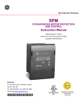
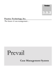
Figure 2–1 shows the basic outline for the Debug Monitor memory map.
Figure 2–1 Debug Monitor Memory Map
Top of Main Memory
8KB Guard Page
Top of Stack
Stack
0x300000
Default Boot Address
(bootadr)
0x200000
DMA Buffers
0x100000
DMA Buffer Base
Debug Monitor Kernel
0x10000
Debug Monitor Entry
Debug Monitor PALcode
0x0
PALcode Base Address
FM-05670.AI4
2–6
Getting Started
8 April 1999
Downloading Files
The Debug Monitor image consists of PALcode at physical address 0 and the Debug
Monitor kernel at physical address 1000016. After loading the image into memory, the
SROM initialization code begins execution of the image in PALmode at the PALcode
base address.
The PALcode used in the Debug Monitor was designed to support Tru64 UNIX and
was later adapted to the Debug Monitor. Refer to the Alpha Architecture Reference
Manual and the PALcode for Alpha Microprocessors System Design Guide for more
information about Tru64 UNIX PALcode.
2.5.1 Stack
PALcode starts execution of the Debug Monitor kernel at physical address 1000016.
Upon entry to the Debug Monitor kernel, the Debug Monitor establishes the initial
stack pointer at the first 8KB boundary below the top of main memory. From there the
stack grows downward.
2.5.2 DMA Buffers
Various devices used with the motherboard require direct memory access (DMA). The
device drivers provided in the Debug Monitor for these devices are designed to perform
their DMA within a 1MB range starting at 1 megabyte (physical address 10000016). At
startup, the Debug Monitor initializes the I/O subsystem with DMA windows that
include this range. The device drivers included with the Debug Monitor that require
DMA are the Ethernet and diskette drivers. Although the ebuff command can be used
to change the base of the Ethernet buffers, the buffers must remain within this 1MB
window.
2.6 Downloading Files
The motherboard supports loading files into memory from a serial port, the Ethernet,
and a diskette. The user can either load the file into memory, or load and execute the file
in a single step. The following table shows the commands for the specific I/O devices.
See Chapter 4 for more details about these commands.
I/O Device
Use this command to
load into memory...
Use this command to
load into memory and execute...
ROM socket
romload
romboot
Serial port
load
boot
Ethernet
netload
netboot
Diskette
flload
flboot
The default boot address (bootadr) is 30000016. However, you can change the default
boot address with the bootadr command. The new setting is then stored in the batterybacked RAM.
8 April 1999
Getting Started
2–7
Execution Commands
2.7 Execution Commands
After your program is loaded, you are ready to execute it. If the command loads and
executes a program, you may want to re-execute the program during the motherboard
session. The Debug Monitor has two commands to execute programs: go and jtopal.
See Chapter 4 for more details about these commands.
2.8 Resetting the Debug Monitor
If the software hangs the motherboard, then the hardware reset on the board can be used
to reset to the Debug Monitor command line. For information about connecting the
reset signals, see your motherboard’s user’s manual.
2–8
Getting Started
8 April 1999
3
Remote Debugging
The Debug Monitor supports remote debugging for Tru64 UNIX host systems with
Ladebug. The Ladebug software provides the full source-level debugging capabilities
of most programs that run on the motherboard, including the Debug Monitor.
This chapter describes some debugging hints to use with the Debug Monitor and the
remote debugger. This chapter also describes the guidelines for writing programs that
allow you to take full advantage of remote debugging.
3.1 What Is a Debugger?
A debugger is a tool that helps you locate run-time programming errors or bugs. You
use the debugger on executable programs created when a program has been compiled
and linked successfully.
3.2 What Is a Remote Debugger?
A remote debugger is a tool that helps you locate run-time programming errors or bugs
in a program running on a remote system. The remote system can be a system that cannot support a full programming environment by itself. You use a remote debugger on
executable programs compiled and linked for the remote system.
3.3 Remote Debug Server
The Debug Monitor’s remote debug server (the part of the monitor that communicates
with Ladebug) uses interrupts and an Ethernet device. Interrupts are used by the Debug
Monitor to poll the Ethernet device for messages from Ladebug. Any program that
changes the interrupt handler must instruct the debug server when to poll the Ethernet.
3.4 Programming Guidelines
The following sections describe the programming guidelines for remote debugging.
3.4.1 The Run-Time Environment
When a program is started by the Debug Monitor’s go command, it is started at the
appropriate IPL to enable real-time clock interrupts (usually IPL 4). If a program does
not install its own interrupt handler, then the Debug Monitor will handle all interrupts.
If a program does install its own interrupt handler using the Write System Entry
8 April 1999
Remote Debugging
3–1
Programming Guidelines
Address PAL call, then it must be prepared to handle all interrupts as described in the
following sections. When a program completes normally, the Debug Monitor reinstalls
its own interrupt handler.
3.4.2 Types of Programs
For the purposes of this chapter, programs may be classified into the following three
types:
•
Programs that do not use the Ethernet or do not include their own interrupt handler
•
Programs that do not use the Ethernet but do include their own interrupt handler
•
Programs that use the Ethernet
3.4.2.1 Restriction
There is only one restriction for programs that do not use the Ethernet and that use the
Debug Monitor interrupt handler. Do not disable the real-time clock interrupt and the
Ethernet interrupts for long periods.
Long delays may cause Ladebug to behave as if there is a problem with the Ethernet
link to the target. If network delays are insignificant, Ladebug will tolerate periods of
up to 10 seconds with interrupts disabled, although it will normally warn the user of
possible network problems if interrupts are disabled for more than a second. Ethernet
interrupts are disabled at IPL 3 or more, and real-time clock interrupts are disabled at
IPL 5 or more. Writing to the control registers of the Ethernet device or to the real-time
clock can also disable the interrupts. It is possible to set breakpoints or to single step
uninterruptible code. There is no restriction on the time that can be spent at the
breakpoint.
Programs that define or install their own interrupt handler must ensure that the Debug
Monitor polls the Ethernet device often enough to receive all the messages sent to it by
Ladebug. An easy way to do this is to use the ladbx_poll function. When this function is called, the following occurs:
•
All frames that have been received on the Ethernet device are read.
•
All remote debug frames are processed and acted upon.
•
Any Ethernet interrupt is cleared.
The ladbx_poll function is a void function that takes no arguments. It must be
called often enough to allow the Debug Monitor to respond promptly to all received
Ethernet frames. To ensure that this function gets called at the proper time, enable either
Ethernet or timer interrupts (or both) and call it every time an interrupt occurs.
Programs cannot share an Ethernet device with the Debug Monitor. The Debug Monitor
can drive a selection of different types of Ethernet devices on ISA or PCI cards, and an
individual Ethernet device can be selected with the Debug Monitor edevice command.
3–2
Remote Debugging
8 April 1999
Ladebug Command Line Options
3.4.3 PALcode Environment
Most programs will be able to use the Tru64 UNIX compatible PALcode included with
the Debug Monitor; however, for the programs that install their own PALcode, the following guidelines must be followed:
•
For remote debug to work, the following Tru64 UNIX PALcode calls must be
implemented according to the interface described in the UNIX section of the Alpha
Architecture Reference Manual.
IMB
RDUSP
RTI
WPIPL
WRENT
•
The interface to the system must conform to the standards described in the
UNIX section of the Alpha Architecture Reference Manual.
•
The debug server uses the DBGSTOP PAL call to implement breakpoints. The program must contain an identical implementation of the DBGSTOP PAL call.
This PAL call, rather than the BPT PAL call, is used because complex programs
(such as operating systems) are likely to reset the EntIF system entry point during
initialization.
•
The program reset PALcode routine must preserve the address of the debug entry
point through the installation of the new PALcode. For the motherboard PALcode,
this address is held in the PAL temporary register with symbolic name ptEntDbg.
The user-defined PALcode must also either preserve the address of the interrupt
entry point (ptEntInt) or set the IPL to a level that prevents all interrupts until the
program sets up its own interrupt handler containing a call to ladbx_poll.
3.5 Ladebug Command Line Options
Versions 1.3 or later of Ladebug provide the command line options shown in Table 3–1 to
support remote debugging.
Table 3–1 Ladebug Command Line Options
8 April 1999
Command Line Option
Description
-rn node_name
Specifies IP node name of the target node. Required for
remote debug. No default.
-pid process_id
Specifies the process id of the process to be debugged. The
Ladebug software debugs a running process rather than
loading a new process.
-rfn arbitrary string
Specifies the file name (or other identifier) of the image to
be loaded on a remote system. Defaults to the local object
file name. Passed to the remote system uninterrupted. Will
often have to be quoted to avoid shell command line
interpretation on the local system. Can be used only with
-rn; do not combine with -pid.
Remote Debugging
3–3
Building the Executable File
Table 3–1 Ladebug Command Line Options (Continued)
Command Line Option
Description
-rinsist
Connects to a running remote process using the connect
insist protocol message instead of the connect protocol
message. This option functions as a request to the server to
connect to the client even if some other client is already
connected. (The previously connected client is
disconnected.) Use only with -rn and -pid.
-rp debug protocol name
Specifies the remote debug protocol to be used. The valid
value and default is ladebug_preemptive.
-rt transport protocol name
Specifies the transport protocol to be used for remote debug.
The valid value and default is UDP.
Note:
The debug server can be used only to debug already loaded processes;
therefore, the pid option must always be specified. Because the Debug
Monitor is not a multiprocessing system, the process id specified with this
option is ignored.
Because using the Debug Monitor with Ladebug is a subset of general Ladebug usage,
the only meaningful command line has the following format, using both the -rn option
and the -pid option:
%ladebug size.out -rn dp264 -pid 0
This example connects to the server on the node with IP node name dp264 and asks to
debug the process with pid 0. The local object file is called size.out. Depending
upon your network environment, you may need to fully specify the IP node name, such
as dp264.mysite.hlo.dec.com.
3.6 Building the Executable File
To build the executable file for remote debugging, follow these steps:
1. Compile your source files using the -g option. This preserves the symbolic
information in the source files.
2. Link the source files with the -N and -Tx options; where x is the load address for the
executable on the motherboard.
3. Use the CSTRIP utility to strip the coff header from the executable file. Keep the
unstripped executable file.
3.7 Starting a Ladebug Session
The Debug Monitor ladebug command configures the motherboard as a remote
debugger target. Communication is performed through the Ethernet connection.
To debug a program running on a motherboard using Ladebug running on a remote
host, follow these steps:
1. Set up the host Tru64 UNIX machine as described in Chapter 2.
2. Start the motherboard.
3. Load the program into memory on the motherboard.
3–4
Remote Debugging
8 April 1999
Starting a Ladebug Session
4. Set a breakpoint in the program.
5. Execute the program. The program will stop at the breakpoint and print the instruction line at that location.
6. Issue the ladebug command. This causes the motherboard to wait for a connection
from Ladebug.
7. From the host system, enter the command to start Ladebug and cause it to connect
to the motherboard.
The following example shows how to set up a sample session:
DP264> netload size
Ethernet Base Address: 360, DMA Mask: 1 = DRQ5
Init Block Address 100000
Init Done.
Ethernet BA-98-76-54-32-01
Attempting BOOTP...success.
my IP address: 16.123.45.67
server IP address: 16.123.45.69
gateway IP address: 16.123.45.69
Loading from /users/eval/boot/size ...
####
DP264> stop 200000
DP264> go
Executing at 0x200000...
00200000: 23DEFFF0
lda
sp, -16(sp)
DP264> ladebug
Ethernet Base Address: 360, DMA Mask: 1 = DRQ5
Init Block Address 100000
Init Done.
Client connected : client is FFFFFFFFA0107F10
The following command, entered from the host system, starts Ladebug and causes it to
connect to the DP264:
% ladebug size.out -rn dp264 -pid 0
Welcome to the Ladebug Debugger Version 1.3.1
-----------------object file name: size.out
machine name: dp264
process id: 0
Reading symbolic information ...done
Connected to remote debugger
(ladebug)
The (ladebug) in the previous example is the Ladebug prompt. You are now ready
to debug a process that is running on the DP264. To end this session and return to the
Debug Monitor command prompt, use the Ladebug quit command to disconnect from
the server.
Refer to the Ladebug documentation for more information about how to run Ladebug.
8 April 1999
Remote Debugging
3–5
4
User Commands
4.1 Overview
This chapter describes how to use the Alpha Microprocessors Motherboard Debug
Monitor commands.
The Debug Monitor supports advanced command line editing, including cursor key
movements and an Emacs-like editing interface. In addition, a history buffer has been
added to facilitate repetition of commands.
Table 4–1 shows the command line editing keypad.
Table 4–1 Command Line Editing Keypad
8 April 1999
Keys
Description
. (period)
Repeats the last command entered.
↑(up arrow)
Ctrl/P1
Scrolls up (older entries) the history buffer.
↓ (down arrow)
Ctrl/N
Scrolls down (newer entries) the history buffer.
← (left arrow)
Ctrl/B
Moves the cursor one character to the left.
→ (right arrow)
Ctrl/F
Moves the cursor one character to the right.
Backspace
Delete
Ctrl/H
Deletes the character preceding the cursor.
Ctrl/D
Deletes character at cursor position.
Ctrl/K
Deletes text from cursor to end of line.
Ctrl/R
Refreshes the current line.
Ctrl/U
Erases the current line of command text.
End2
Ctrl/E
Moves to the end of the line.
Esc/B
Moves the cursor to the previous word.
Esc/Backspace
Esc/DELETE
Deletes the previous word.
Esc/D
Deletes the next word.
User Commands
4–1
Using the Commands
Table 4–1 Command Line Editing Keypad (Continued)
Keys
Description
Esc/F
Moves the cursor to the next word.
Home2
Ctrl/A1
Moves to the beginning of the line.
Insert
Toggles between insert and overwrite mode.
Return
Ctrl/J
Ctrl/M
Enters the current command.
1
If you connected to the motherboard through the Tru64 UNIX tip command, you must press
Ctrl/P twice to obtain the normal effect of Ctrl/P.
2
This key requires that the keyboard be connected directly to the motherboard.
4.2 Using the Commands
This section describes the Debug Monitor command categories.
•
Download and execution commands
The motherboard software basic load command expects to receive Motorola
S-records that are stored in the appropriate memory location. The Ethernet port
provides improved download performance by using the Internet BOOTP protocol
(a UDP-based protocol). This feature allows the motherboard system to determine
its Internet address, the address of a boot server, and the name of a file to boot. The
Debug Monitor also supports loading files from a floppy drive or the secondary
ROM socket.
The execution commands can be used to transfer control to a program in memory.
These commands begin executing a program in memory at the specified address, or
automatically with a download command.
•
Examine and modify memory commands
These commands are used to examine and change memory in various formats
beginning at a specified address and ending at a specified address. Quadwords (64
bits), longwords (32 bits), halfwords (16 bits), and bytes (8 bits) are all supported
by these commands.
•
PCI commands
These commands are used to access PCI configuration space.
•
Utility commands
These commands are used to display and modify the date and time, display the version of the Debug Monitor, and obtain information about commands implemented
in the current version.
•
Debug commands
These commands are used to debug software. Debug commands display internal
CPU registers and provide debug capabilities, including breakpoints and single
stepping.
4–2
User Commands
8 April 1999
User Commands Quick Reference
•
Miscellaneous commands
These commands are used to read and write the system register, perform an
interrupt acknowledge cycle, call a subroutine, and connect to serial
communication ports.
•
Ethernet commands
These commands are used to set up and verify the status of the Ethernet port.
•
Diagnostic commands
These commands are used to verify that the motherboard is working properly.
4.3 User Commands Quick Reference
Table 4–2 contains a summary of all Debug Monitor commands. The commands are
grouped by category and function.
Table 4–2 Command Summary Table
Command
Parameters
Description
Download and Execution Commands
load
address
Downloads a file through the active serial port using the XMODEM
protocol.
boot
address
Downloads a file through the active serial port using the XMODEM
protocol and begins execution.
netload
file, address
Downloads the specified file through the Ethernet port at the current
boot address or specified address.
netboot
file, address
Downloads the specified file through the Ethernet port and begins execution.
flcd
drive_pathname
Changes the current working directory to the specified drive or path.
flcopy
source_file,
destination_file
Copies the specified file to another location.
fldir
drive_pathname
Displays a list of files in the current or specified directory.
flload
file, address
Downloads the specified diskette file.
flboot
file, address
Downloads the specified diskette file and begins execution.
flread
first_sector, bytes,
dest_address, iterations, drive
Reads logical sectors from a diskette.
flwrite
first_sector,
Writes data by logical sectors to a diskette.
image_size,
source_address, iterations, drive
flsave
file_name,
start_address,
file_size
Saves the specified memory range to the specified file.
romload
type, address
Loads the specified image from ROM to the specified address.
romboot
type, address
Loads the specified image from ROM and begins execution.
8 April 1999
User Commands
4–3
User Commands Quick Reference
Table 4–2 Command Summary Table (Continued)
Command
Parameters
Description
romlist
none
Lists the ROM image headers contained in ROM.
romverify
type, address
Compares an image in memory to an image in ROM.
bootadr
address
Sets default boot address.
bootopt
type
Selects the operating system and firmware type to be used on the next
power-up.
go
start_address
Starts execution at the specified address.
jtopal
start_address
Starts execution at the specified address in PALmode.
init
none
Reinitializes the Debug Monitor.
Examine and Modify Memory Commands
emb
address, iterations,
silent
Examines and displays a byte of data in memory.
eml
address, iterations,
silent
Displays longword of data at the specified memory address.
emq
address, iterations,
silent
Displays quadword of data at the specified memory address.
emw
address, iterations,
silent
Examines and displays a word of data in memory.
ddmq
address, data, iterations
Deposits the specified quadword of data in the specified memory
address.
dmb
address, data, iterations
Deposits the specified byte of data in the specified memory address.
dml
address, data, iterations
Deposits the specified longword of data in the specified memory
address.
dmq
address, data, iterations
Deposits the specified quadword of data in the specified memory
address.
dmw
address, data, iterations
Deposits the specified word of data in the specified memory address.
mt
none
Measures memory bandwidth.
pq
start_address,
end_address, iterations, silent
Prints memory in quadword (64-bit) format.
pl
start_address,
end_address, iterations, silent
Prints memory in longword (32-bit) format.
pw
start_address,
end_address, iterations, silent
Prints memory in word (16-bit) format.
pb
start_address,
end_address, iterations, silent
Prints memory in byte (8-bit) format.
cq
address
Edits memory quadwords (64-bit).
4–4
User Commands
8 April 1999
User Commands Quick Reference
Table 4–2 Command Summary Table (Continued)
Command
Parameters
Description
cl
address
Edits memory longwords (32-bit).
cw
address
Edits memory words (16-bit).
cb
address
Edits memory bytes (8-bit).
fill
start_address,
end_address,
fill_value
Fills the specified memory block with the specified 32-bit pattern.
copy
Copies a memory range to the specified address.
start_address,
end_address, destination
compare
start_address,
end_address,
compare_address
Compares a memory range to a specified address.
dis
start_address,
end_address
Displays memory as CPU instructions.
sum
start_address,
end_address
Prints a checksum of a memory range.
rl
register, iterations,
silent
Reads a longword from a register port in I/O address space.
rw
register, iterations,
silent
Reads a word from a register port in I/O address space.
rb
register, iterations,
silent
Reads a byte from a register port in I/O address space.
wl
register, data, iterations
Writes a longword to a register port in I/O address space.
ww
register, data, iterations
Writes a word to a register port in I/O address space.
wb
register, data, iterations
Writes a byte to a register port in I/O address space.
mrl
address, iterations,
silent
Reads a longword from memory in I/O address space.
mrw
address, iterations,
silent
Reads a word from memory in I/O address space.
mrb
address, iterations,
silent
Reads a byte from memory in I/O address space.
mwl
address, data, iterations
Writes a longword to memory in I/O address space.
mww
address, data, iterations
Writes a word to memory in I/O address space.
mwb
address, data, iterations
Writes a byte to memory in I/O address space.
8 April 1999
User Commands
4–5
User Commands Quick Reference
Table 4–2 Command Summary Table (Continued)
Command
Parameters
Description
sq
start_address,
end_address, string,
inverse
Searches the specified memory range by quadwords for the specified
pattern.
sl
start_address,
end_address, string,
inverse
Searches the specified memory range by longwords for the specified
pattern.
sw
start_address,
end_address, string,
inverse
Searches the specified memory range by words for the specified pattern.
sb
start_address,
end_address, string,
inverse
Searches the specified memory range by bytes for the specified pattern.
PCI Commands
pcishow
id, bus, function
Displays the contents of each PCI slot and current PCI to system
address space mapping.
prl
pci_address, id, bus,
function
Reads a longword from the specified address in PCI configuration
space.
prw
pci_address, id, bus,
function
Reads a word from the specified address in PCI configuration space.
prb
pci_address, id, bus,
function
Reads a byte from the specified address in PCI configuration space.
pwl
pci_address, id, data, Writes a longword to a specified address in PCI configuration space.
bus, function
pww
pci_address, id, data, Writes a word to a specified address in PCI configuration space.
bus, function
pwb
pci_address, id, data, Writes a byte to a specified address in PCI configuration space.
bus, function
Utility Commands
date
yymmddhhmmss
Modifies or displays the date and time.
flash
source_address,
destination_offset,
bytes_to_write
Programs data into flash memory.
flasherase
starting_offset,
bytes_to_erase
Erases data from flash memory.
fwupdate
none
Loads and runs the firmware update utility.
help
command_name
Displays a list of commands or displays parameter fields and syntax if
a command is specified.
apropos
keyword
Displays help text containing the specified keyword.
ident
start_address,
end_address
Displays RCS ID strings found in the specified memory range.
sysshow
none
Displays SROM parameters.
version
none
Displays the Debug Monitor firmware version information.
4–6
User Commands
8 April 1999
User Commands Quick Reference
Table 4–2 Command Summary Table (Continued)
Command
Parameters
Description
swpipl
ipl
Sets or displays the current interrupt priority level (IPL) of the CPU.
mces
mces_data
Sets or displays the machine check error summary register.
wrfen
value
Enables/disables floating point.
Debug Commands
preg
address
Displays CPU general-purpose registers.
pfreg
address
Displays CPU floating-point registers.
creg
register_number,
value
Modifies CPU general-purpose registers.
cfreg
register_number,
value
Modifies CPU floating-point registers.
stop
address
Sets a breakpoint at the specified address.
bpstat
none
Displays the current breakpoint status.
step
none
Executes a machine instruction by stepping into the first instruction of
the function being called.
next
none
Executes a machine instruction without stepping into subroutines.
cont
none
Continues execution from a breakpoint.
delete
address
Removes breakpoint from the specified address.
ladebug
none
Starts a Ladebug server for a remote debug session.
Miscellaneous Commands
cominit
none
Initializes communications ports.
iack
none
Performs an interrupt acknowledge cycle.
rmode
mode
Sets the dis command register display mode.
setty
port
Specifies the port used for Debug Monitor interaction.
setbaud
port, baud_rate
Sets the communication port baud rate. The default is 9600.
tip
port
Connects to a specified serial communication port.
vinit
none
Initializes the video controller.
Ethernet Commands
edevice
device_number
Selects a registered Ethernet device.
eshow
none
Displays all registered Ethernet devices.
ereg
none
Displays the Ethernet controller registers.
estat
none
Displays Ethernet statistics.
einit
none
Initializes Ethernet controller and displays the Ethernet hardware
address.
estop
none
Stops the Ethernet controller.
ebuff
address
Sets the base address for Ethernet DMA buffers.
8 April 1999
User Commands
4–7
User Commands
Table 4–2 Command Summary Table (Continued)
Command
Parameters
Description
edmp
status
Sets or clears display of packets received or transmitted.
eprom
status
Sets or clears flag for receiving all packets (promiscuous mode).
arpshow
none
Displays all known address resolution protocol (ARP) entries.
Diagnostic Commands
beep
duration, frequency
Causes speaker to beep for the specified duration and frequency.
mcheck
state
Controls the reporting of hardware error conditions (machine checks).
memtest
iterations,
start_address,
end_address, increment, mcheck,
stop_drivers
Tests memory range. Uses longword accesses to memory.
4.4 User Commands
This section contains complete descriptions and examples of the Debug Monitor commands. The commands are listed in alphabetical order.
4–8
User Commands
8 April 1999
User Commands
4.4.1 apropos — Display Help Descriptions
The apropos command displays help descriptions for the specified keyword.
Format
apropos keyword
Parameters
keyword
Specifies the string to match in the help command text.
Description
The apropos command is an additional form of help. This command searches the help
file and displays all matches for the specified keyword.
Example
DP264> apropos load
load:
Downloads S records through a serial port
syntax: load
arguments:
boot:
Downloads S records through a serial port and begins execution
syntax: boot
arguments:
netload:
Downloads file via the Ethernet
to bootadr
syntax: netload file address
arguments: <opt str> <opt hex>
port
to
address. Address defaults
netboot:
Downloads file through the Ethernet port and begins execution
syntax: netboot file address
arguments: <opt str> <opt hex>
Hit any key to continue. Control-C to quit...
8 April 1999
User Commands
4–9
User Commands
4.4.2 arpshow — Display Known Address Resolution Protocol Entries
The arpshow command displays all known address resolution protocol (ARP) entries.
Format
arpshow
Parameters
None.
Description
The arpshow command displays an IP routing table entry. If there are no ARP entries,
nothing is shown for that device. The Ethernet device number displayed matches the
number that is displayed when the eshow and edevice commands are entered.
Example
DP264> arpshow
Arp Table Contents (at 0x00074570):
Ethernet Device 0
IP Address: 16.123.45.67
MAC Address: BA-98-76-54-32-10
4–10
User Commands
8 April 1999
User Commands
4.4.3 beep — Test Speaker
The beep command tests the speaker.
Format
beep duration frequency
Parameters
duration
Specifies the duration of the beep in milliseconds.
frequency
Specifies the frequency in hertz.
Description
The beep command causes the speaker to beep for the specified duration and frequency.
Example
DP264> beep 1000 4000
8 April 1999
User Commands
4–11
User Commands
4.4.4 boot — Download File Using XMODEM Protocol
The boot command downloads a file through the active serial port using the XMODEM
protocol and begins execution.
Format
boot [address]
Parameters
address
Specifies the address at which to download the file. The default is the boot address.
Description
The boot command uses the XMODEM protocol to download a file through the active
serial port. The program is loaded to the supplied address or to the boot address if an
address is not specified. The program is then automatically executed.
Example
In this example, a Tru64 UNIX host system is connected to the motherboard on device
/dev/tty01. The sx command sends a file using XMODEM.
% echo boot 300000 > /dev/tty01
% sx -kt 10 /users/eval1/demo2/size </dev/tty01 >/dev/tty01
Sector nnn
% tip /dev/tty01
DP264>
4–12
User Commands
8 April 1999
User Commands
4.4.5 bootadr — Display or Modify Default Boot Address
The bootadr command allows you to display or modify the default boot address.
Format
bootadr [address]
Parameters
address
Specifies the starting address at which a program is loaded. Programs loaded with the
netboot command automatically begin program execution at this address. The default
address is 30000016.
Description
The boot address is the address at which your programs load and begin execution. The
bootadr command sets the default address for the load commands to begin execution or
to download your program into memory. If the bootadr command is specified without
an address, the command displays the current default boot address. If you set the boot
address value, the value is stored in battery-backed RAM.
Example
This example sets the starting address to 2000016. The next file that is loaded begins
execution from this address.
DP264> bootadr 20000
8 April 1999
User Commands 4–13
User Commands
4.4.6 bootopt — Select Operating System and Firmware
The bootopt command selects the operating system and firmware type to be used on
the next power-up.
Format
bootopt [type]
Parameters
type
Specifies the operating system type. If the specified image is not found at power-up, the
first image is booted. If there are no ROM headers, the whole ROM will be loaded at
address 0.
Description
The bootopt command selects the operating system and associated firmware type that
will be used the next time you power up your motherboard. If no type is specified, a list
of predefined types is displayed along with the current selection. Use the romlist command to display the images contained in the ROM. You can specify the type as a number or a name.
Type_number
Type_name
Description
0
DBM
Alpha Motherboard Debug Monitor
1
NT
Windows NT
2
VMS
OpenVMS
3
UNIX
Tru64 UNIX
7
LINUX
Linux, MILO
8
VXWORKS
VxWorks
10
SROM
Serial ROM
The bootopt command can also be used to select a ROM image based on its position in
the ROM. Specifying the type as #0 selects the whole ROM. Specifying the type as #1
selects the first image; #2 selects the second image, and so on.
Example
DP264> bootopt
Predefined bootoptions are...
“0” “Alpha Evaluation Board Debug Monitor” “DBM”
“1” “The Windows NT Operating System” “NT”
“2” “OpenVMS” “VMS”
“3” “Tru64 UNIX” “UNIX”
“7” “Linux” “Milo”
“8” “VxWorks. Real-Time Operating System” “VxWorks”
“10” “Serial ROM (SROM)” “SROM”
O/S type selected: “OpenVMS”
....Firmware type: “Alpha SRM Console”
DP264> bootopt 0
O/S type selected: “Alpha Evaluation Board Debug Monitor”
....Firmware type: “Alpha Evaluation Board Debug Monitor”
DP264> bootopt nt
O/S type selected: “The Windows NT Operating System”
....Firmware type: “Windows NT Firmware”
4–14
User Commands
8 April 1999
User Commands
DP264> bootopt #1
Firmware image 1 selected.
....Firmware type: “Unknown”
DP264> bootopt unix
O/S type selected: “Tru64 UNIX”
....Firmware type: “Alpha SRM Console”
DP264> bootopt #0
Load and boot entire ROM at address zero.
....Firmware type: “Unknown”
DP264> bootopt
Predefined bootoptions are...
“0” “Alpha Evaluation Board Debug Monitor” “DBM”
“1” “The Windows NT Operating System” “NT”
“2” “OpenVMS” “VMS”
“3” “Tru64 UNIX” “UNIX”
“7” “Linux” “Milo”
“8” “VxWorks. Real-Time Operating System” “VxWorks”
“10” “Serial ROM (SROM)” “SROM”
Load and boot entire ROM at address zero.
....Firmware type: “Unknown”
8 April 1999
User Commands 4–15
User Commands
4.4.7 bpstat — Display Breakpoint Status
The bpstat command displays the current breakpoint status.
Format
bpstat
Parameters
None.
Description
The bpstat command lists the breakpoints set with the stop command. The disassembled instructions for that location are also displayed.
Example
DP264> stop 200000
DP264> stop 200FC0
DP264> bpstat
{break} at 00200000:
{break} at 00200FC0:
4–16
User Commands
23DEFFF0
27BB0001
lda
ldah
sp, -16(sp)
r29, 1(r27)
8 April 1999
User Commands
4.4.8 cb — Edit Memory Bytes
The cb command allows you to edit memory bytes (8-bit).
Format
cb [address]
Parameters
address
Specifies the address of the memory byte you want to change.
Description
The cb command allows you to modify the contents of a specified memory address. If
no address is specified, then the next byte is selected. The Debug Monitor displays the
address followed by the current data and a colon (:). For example:
0200090:
1D :
To modify the contents of this memory location, type the new data after the colon and
press the Return key. To end the editing of memory locations, type any
nonalphanumeric character except a period (.). The nonalphanumeric character can be
typed after the modified byte (on the same line). To leave the current location
unchanged, press the Return key on an empty line.
Example
In this example, the bytes at 30000016 and 30000316 have been modified, leaving the
ones at 30000116 and 30000216 unchanged.
DP264> pb 300000 300008
00300000: 1f 04 ff 47 1f 04 ff 47 45 00 60 c3 00 00 00 00 ...G...GE.‘.....
DP264> cb 300000
00300000: 1f: aa
00300001: 04:
00300002: ff:
00300003: 47: dd
00300004: 1f: ;
DP264> pb 300000 300008
00300000: aa 04 ff dd 1f 04 ff 47 45 00 60 c3 00 00 00 00 .......GE.‘.....
8 April 1999
User Commands 4–17
User Commands
4.4.9 cfreg — Modify CPU Floating-Point Register
The cfreg command modifies the saved CPU floating-point register state.
Format
cfreg register_number value
Parameters
register_number
Identifies the register.
value
Specifies the new value of the register in hexadecimal numbers.
Description
The cfreg command modifies the saved CPU floating-point register state to contain the
specified value.
The program register contents are stored in memory to the saved-state area when a
breakpoint is encountered. Modifications to a register using the cfreg command are
applied to that register when execution of the program is resumed using the step or the
cont command.
Example
DP264> pfreg
Floating Point Registers
register file @: 0000C840
f00: 0000000000000000 0000000000000000 0000000000000000
f04: 0000000000000000 0000000000000000 0000000000000000
f08: 0000000000000000 0000000000000000 0000000000000000
f12: 0000000000000000 0000000000000000 0000000000000000
f16: 0000000000000000 0000000000000000 0000000000000000
f20: 0000000000000000 0000000000000000 0000000000000000
f24: 0000000000000000 0000000000000000 0000000000000000
f28: 0000000000000000 0000000000000000 0000000000000000
PC: 000000000000000D PS: 000000000000000D
DP264> cfreg 12 ababababab
DP264> cfreg 14 fefefefefe
DP264> pfreg
Floating Point Registers
register file @: 0000C840
f00: 0000000000000000 0000000000000000 0000000000000000
f04: 0000000000000000 0000000000000000 0000000000000000
f08: 0000000000000000 0000000000000000 0000000000000000
f12: 000000ABABABABAB 0000000000000000 000000FEFEFEFEFE
f16: 0000000000000000 0000000000000000 0000000000000000
f20: 0000000000000000 0000000000000000 0000000000000000
f24: 0000000000000000 0000000000000000 0000000000000000
f28: 0000000000000000 0000000000000000 0000000000000000
PC: 000000000000000D PS: 000000000000000D
4–18
User Commands
0000000000000000
0000000000000000
0000000000000000
0000000000000000
0000000000000000
0000000000000000
0000000000000000
0000000000000000
0000000000000000
0000000000000000
0000000000000000
0000000000000000
0000000000000000
0000000000000000
0000000000000000
0000000000000000
8 April 1999
User Commands
4.4.10 cl — Edit Memory Longwords
The cl command allows you to edit memory longwords (32-bit).
Format
cl [address]
Parameters
address
Specifies the address of the memory longword you want to change.
Description
The cl command allows you to modify the contents of a specified memory address. If
no address is specified, then the next longword is selected. The Debug Monitor displays
the address followed by the current data and a colon (:). For example:
00200090:
E7E0101D :
To modify the contents of this memory location, type the new data after the colon and
press the Return key. To end the editing of memory locations, type any
nonalphanumeric character except a period (.). The nonalphanumeric character can be
typed after the modified byte (on the same line). To leave the current location
unchanged, press the Return key on an empty line.
Example
In this example, the memory data at address 0 has been modified from 91E01122 to
E7E01021.
DP264> cl 0
00000000: 91E01122: e7e01021
DP264> pl 0 0
00000000: E7E01021 00000000 00000000 00000000 !...............
8 April 1999
User Commands 4–19
User Commands
4.4.11 cominit — Initialize Communications Ports
The cominit command initializes communications ports.
Format
cominit
Parameters
None.
Description
The cominit command initializes communications ports.
Example
DP264> cominit
4–20
User Commands
8 April 1999
User Commands
4.4.12 compare — Compare Memory Range
The compare command compares a memory range to a specified address.
Format
compare start_address end_address compare_address
Parameters
start_address
Specifies the memory address at which to start the comparison.
end_address
Specifies the last address that will be compared.
compare_address
Specifies the address to be compared to the memory range.
Description
The compare command compares each longword (32 bits) within a specified range in
memory to another specified location. It then prints the data that differ.
Example
DP264> copy 3fff80000 3fffd0000 400000
DP264> fill 400200 400220
DP264> fill 400400 400440 ffffffff
DP264> compare 3fff80000 3fffd0000 400000
3FFF80200: 64 86 00 E7 64 00 80 FF 00400200: 00
3FFF80208: 7B 06 78 C3 44 A0 10 C0 00400208: 00
3FFF80210: F4 9B 10 E0 C3 80 00 80 00400210: 00
3FFF80218: 00 CC 00 64 83 00 84 74 00400218: 00
3FFF80400: E2 39 37 05 49 99 76 26 00400400: FF
3FFF80408: 4B 96 16 C4 4A 36 B7 C1 00400408: FF
3FFF80410: 4A 16 04 36 43 00 90 D6 00400410: FF
3FFF80418: 6E 0D 00 C0 E2 20 00 08 00400418: FF
3FFF80420: 75 40 00 D6 76 42 00 D6 00400420: FF
3FFF80428: 76 97 00 08 65 88 00 D6 00400428: FF
3FFF80430: 66 95 00 39 67 00 80 FF 00400430: FF
3FFF80438: 79 7B 44 00 39 67 99 36 00400438: FF
3FFFD0000: FF FF FF FF FF FF FF FF 00450000: 2D
8 April 1999
00
00
00
00
FF
FF
FF
FF
FF
FF
FF
FF
00
00
00
00
00
FF
FF
FF
FF
FF
FF
FF
FF
00
00
00
00
00
FF
FF
FF
FF
FF
FF
FF
FF
00
00
00
00
00
FF
FF
FF
FF
FF
FF
FF
FF
00
00
00
00
00
FF
FF
FF
FF
FF
FF
FF
FF
00
00
00
00
00
FF
FF
FF
FF
FF
FF
FF
FF
00
00
00
00
00
FF
FF
FF
FF
FF
FF
FF
FF
00
User Commands 4–21
User Commands
4.4.13 cont — Continue Execution from Breakpoint
The cont command continues execution from a breakpoint.
Format
cont
Parameters
None.
Description
The cont command continues from a breakpoint. The program continues until another
breakpoint or the end of the program is reached.
Example
DP264> stop 100000
DP264> go
Executing at 0x100000...
00100000: C1000003
br
r8, 100010
DP264> step
00100010: 2F880007
ldq_u
r28, 7(r8)
DP264> step
00100014: A49E0000
ldq
r4, 0(sp)
DP264> cont
This simple program prints the sizes of
various data types in bytes.
char
= 1
short = 2
int
= 4
long
= 8
float = 4
double = 8
4–22
User Commands
8 April 1999
User Commands
4.4.14 copy — Copy Memory Block
The copy command copies the specified memory range to the new specified address.
Format
copy start_address end_address destination
Parameters
start_address
Specifies the starting address for this copy.
end_address
Specifies the last address to be included in this copy.
destination
Specifies the new starting address for the memory range.
Description
The copy command copies the data from the specified block of memory to a new location in memory. The original location is unchanged.
Example
This example displays the original location and the destination before and after the
copy command.
DP264> pl 8000000
08000000: 1F1F1F1F 1F1F1F1F
08000010: 1F1F1F1F 1F1F1F1F
08000020: 1F1F1F1F 1F1F1F1F
08000030: 1F1F1F1F 1F1F1F1F
08000040: 1F1F1F1F 1F1F1F1F
08000050: 1F1F1F1F 1F1F1F1F
08000060: 1F1F1F1F 1F1F1F1F
08000070: 1F1F1F1F 1F1F1F1F
DP264> pl 9000150
09000150: 00000000 00000000
09000160: 00000000 00000000
09000170: 00000000 00000000
09000190: 00000000 00000000
090001A0: 00000000 00000000
090001B0: 00000000 00000000
090001C0: 00000000 00000000
DP264> copy 8000000 8000080
DP264> pl 9000150
09000150: 1F1F1F1F 1F1F1F1F
09000160: 1F1F1F1F 1F1F1F1F
09000180: 1F1F1F1F 1F1F1F1F
09000190: 1F1F1F1F 1F1F1F1F
090001A0: 1F1F1F1F 1F1F1F1F
090001B0: 1F1F1F1F 1F1F1F1F
090001C0: 1F1F1F1F 1F1F1F1F
DP264> pl 8000000
08000000: 1F1F1F1F 1F1F1F1F
08000010: 1F1F1F1F 1F1F1F1F
08000020: 1F1F1F1F 1F1F1F1F
08000030: 1F1F1F1F 1F1F1F1F
08000040: 1F1F1F1F 1F1F1F1F
08000050: 1F1F1F1F 1F1F1F1F
08000060: 1F1F1F1F 1F1F1F1F
08000070: 1F1F1F1F 1F1F1F1F
8 April 1999
1F1F1F1F
1F1F1F1F
1F1F1F1F
1F1F1F1F
1F1F1F1F
1F1F1F1F
1F1F1F1F
1F1F1F1F
1F1F1F1F
1F1F1F1F
1F1F1F1F
1F1F1F1F
1F1F1F1F
1F1F1F1F
1F1F1F1F
1F1F1F1F
................
................
................
................
................
................
................
................
00000000
00000000
00000000
00000000
00000000
00000000
00000000
9000150
00000000
00000000
00000000
00000000
00000000
00000000
00000000
................
................
................
................
................
................
................
1F1F1F1F
1F1F1F1F
1F1F1F1F
1F1F1F1F
1F1F1F1F
1F1F1F1F
1F1F1F1F
1F1F1F1F
1F1F1F1F
1F1F1F1F
1F1F1F1F
1F1F1F1F
1F1F1F1F
1F1F1F1F
................
................
................
................
................
................
................
1F1F1F1F
1F1F1F1F
1F1F1F1F
1F1F1F1F
1F1F1F1F
1F1F1F1F
1F1F1F1F
1F1F1F1F
1F1F1F1F
1F1F1F1F
1F1F1F1F
1F1F1F1F
1F1F1F1F
1F1F1F1F
1F1F1F1F
1F1F1F1F
................
................
................
................
................
................
................
................
User Commands 4–23
User Commands
4.4.15 cq — Edit Memory Quadwords
The cq command allows you to edit memory quadwords (64-bit).
Format
cq [address]
Parameters
address
Specifies the address of the memory quadword you want to change.
Description
The cq command allows you to modify the contents of the specified memory address. If
no address is specified, then the next quadword is selected. The Debug Monitor displays the address followed by the current data and a colon (:). For example:
00200090:
00000000E7E0101D :
To modify the contents of this memory location, type the new data after the colon and
press the Return key. To end the editing of memory locations, type any
nonalphanumeric character except a period (.). The nonalphanumeric character can be
typed after the modified byte (on the same line). To leave the current location
unchanged, press the Return key on an empty line.
Example
This example modifies only quadword 20002016.
DP264> cq 200020
00200020:
00200028:
00200030:
00200038:
00200040:
DP264> pq
00200000:
00200010:
00200020:
00200030:
00200040:
00200050:
00200060:
00200070:
4–24
User Commands
0000000004000000: 0000000011111111
0000000000000000:
3402010400120106:
0402010004020100:
FBFDFEFFFFFDFEFF: ;
200000
FA7D7299CE7F3299 DA65FA99DA7D32D9 .2...r}..2}...e.
FFFFFFFBFBFFFFDB FFFFFFFFFFFFFFFF ................
0000000011111111 0000000000000000 ................
3402010400120106 0402010004020100 .......4........
FBFDFEFFFFFDFEFF FBFDFEFFFBFDFEFF ................
CFE7FF99CB6FF799 EEE7FBFBFFFFFFFF ..o.............
0000000004020000 0000000000000000 ................
1402010620100106 050A050004020100 ... ............
8 April 1999
User Commands
4.4.16 creg — Modify Register State
The creg command modifies the saved CPU general-purpose register state.
Format
creg register_number value
Parameters
register_number
Identifies the register.
value
Specifies the new value of the register in hexadecimal numbers.
Description
The creg command modifies the saved CPU general-purpose register state to contain
the specified value.
The program register contents are stored in memory to the saved-state area when a
breakpoint is encountered. Modifications to a register using the creg command are
applied to that register when execution of the program is resumed using the step or cont
command.
Example
DP264> preg
General Purpose Registers
register file @: 0000C040
r00: 0000000000000020 0000000000000005 000000000000C000
r04: 00000000000003F8 0000000000000000 0000000000000000
r08: FFFFFC000005F470 0000000000027340 0444306453605341
r12: 208090EA6024C19C 882C08AA92065B2D 4100610AE100244F
r16: 0000000000100000 000000000000000D 0000000000000006
r20: 0000000E20026335 5619A46B2B1A5125 0000000000000000
r24: 0000000000000003 0000000000000000 FFFFFC0000042C3C
r28: FFFFFC02C0000000 FFFFFC000006C1E0 0000000000FFDF40
PC: 000000000000000D PS: 000000000000000D
DP264> creg 04 555
DP264> preg
General Purpose Registers
register file @: 0000C040
r00: 0000000000000020 0000000000000005 000000000000C000
r04: 0000000000000555 0000000000000000 0000000000000000
r08: FFFFFC000005F470 0000000000027340 0444306453605341
r12: 208090EA6024C19C 882C08AA92065B2D 4100610AE100244F
r16: 0000000000100000 000000000000000D 0000000000000006
r20: 0000000E20026335 5619A46B2B1A5125 0000000000000000
r24: 0000000000000003 0000000000000000 FFFFFC0000042C3C
r28: FFFFFC02C0000000 FFFFFC000006C1E0 0000000000FFDF40
PC: 000000000000000D PS: 000000000000000D
8 April 1999
000000000000000D
000000000000000D
0A110C485F6EA26E
9E2891ACA8A9D984
0000000000000030
000000000000000D
0000000000100000
0000000000000003
000000000000000D
000000000000000D
0A110C485F6EA26E
9E2891ACA8A9D984
0000000000000030
000000000000000D
0000000000100000
0000000000000003
User Commands 4–25
User Commands
4.4.17 cw — Edit Memory Words
The cw command allows you to edit memory words (16-bit).
Format
cw [address]
Parameters
address
Specifies the address of the memory word you want to change.
Description
The cw command allows you to modify the contents of the specified memory address.
If no address is specified, then the next word is selected. The Debug Monitor displays
the address followed by the current data and a colon (:). For example:
00200090:
101D :
To modify the contents of this memory location, type the new data after the colon and
press the Return key. To end the editing of memory locations, type any nonalphanumeric character except a period (.). The nonalphanumeric character can be typed after
the modified byte (on the same line). To leave the current location unchanged, press the
Return key on an empty line.
Example
This example modifies words 20009416 through 20009816.
DP264> pw
00200090:
002000A0:
002000B0:
002000C0:
002000D0:
002000E0:
002000F0:
00200100:
DP264> cw
00200090:
00200092:
00200094:
00200096:
00200098:
0020009A:
DP264> pw
00200090:
4–26
User Commands
200090
3BB9 CA6D FFB9
0000 0400 0000
8166 309A 4166
FEFF FFFD FEFF
3399 DA65 BB99
0000 0000 0000
8142 2012 0166
FEFF FFFD FEFF
200090
3BB9:
CA6D:
FFB9: ffff
CFE7: 0000
3FBF: 0101
FFFF: ;
200090 20009A
3BB9 CA6D FFFF
CFE7
0000
3402
FBFD
CFF7
0000
3402
FBFD
3FBF
0000
8960
FEFF
37BF
0000
8140
FEFF
FFFF
0000
0402
FBFD
FFFF
0000
0402
FBFD
33F9
0000
8D46
FEFF
33D9
0000
4504
FEFF
CE67.;m......?...3g.
0000................
359Af..0fA.4‘...F..5
FBFD................
CE67.3e......7...3g.
0000................
049A [email protected]..
FBFD...............
0000 0101 FFFF 33F9 CE67.;m..........3g.
8 April 1999
User Commands
4.4.18 date — Display or Modify Date and Time
The date command displays or modifies the date and time.
Format
date [yymmddhhmmss]
Parameters
yymmddhhmmss
To modify the date, supply the year, month, day, hour, minute, and second.
Description
If the date command is specified alone, the month, day, time, and year is displayed. If
you supply a parameter, the date is modified.
Example
This example displays the current date and time setting.
DP264> date
Jun 1 12:58:19 1999
These examples show how to modify the date and time setting.
DP264>
DP264>
Feb 11
DP264>
DP264>
Feb 11
8 April 1999
date 930211000000
date
00:00:04 1999
date 930211135700
date
13:57:02 1999
User Commands 4–27
User Commands
4.4.19 ddmq — Deposit Quadword in Memory
The ddmq command deposits a quadword of data in the specified memory location.
Format
ddmq address data [iterations]
Parameters
address
Specifies the memory address.
data
Specifies the quadword of data to be stored.
iterations
Specifies how many times the command is executed. The default is 1.
Description
The ddmq command deposits the specified quadword of data in the specified memory
location. A memory barrier (MB) instruction is executed after the store to force the
stored data out of the chip.
Example
DP264> ddmq d0000 00000000FC04FF00
4–28
User Commands
8 April 1999
User Commands
4.4.20 delete — Remove Breakpoint from Address
The delete command removes a breakpoint from the specified address.
Format
delete address
Parameters
address
Specifies the address from which to delete the breakpoint.
Description
The delete command removes a breakpoint from the specified address. You can use an
asterisk (*) to remove all breakpoints.
Example
DP264> delete 00200050
8 April 1999
User Commands 4–29
User Commands
4.4.21 dis — Disassemble Instructions
The dis command displays memory as CPU instructions.
Format
dis [start_address [end_address]]
Parameters
start_address
Specifies the address at which to start disassembling instructions. If the start_address is
not specified, the address of the last load command, the last breakpoint, or the last dis
command is used.
end_address
Specifies the address at which to end disassembling instructions. The default is the
start_address plus 32 bytes (8 instructions).
Description
The dis command disassembles instructions starting with the specified address. You
can specify an address range of instructions to be disassembled. If no parameters are
specified, then the command starts with the current address and disassembles the next
eight instructions. If a file is downloaded to memory, then the default starting address
for the dis command is the first memory location in the downloaded file. If a breakpoint
is encountered, then the default starting address is the breakpoint address.
The rmode command is used to select whether the hardware or software register names
are displayed when instructions are disassembled. The hardware register names are
shown by default. The rmode setting is stored in nonvolatile RAM.
Example
DP264> dis 243a0
000243A0:
43020122
000243A4:
48441722
000243A8:
74420050
000243AC:
64630082
000243B0:
209F07E1
000243B4:
48855724
000243B8:
44640103
000243BC:
47203019
DP264> dis
000243C0:
4B037698
000243C4:
4703F118
000243C8:
47190418
000243CC:
4B055738
000243D0:
44780403
000243D4:
746300A2
000243D8:
77FF0055
000243DC:
77FF0000
DP264>
4–30
User Commands
subl
sll
mt
mf
lda
sll
bic
and
r24, r2, r2
r2, 0x20, r2
r2, cc
r3, pt2
r4, 2017(zero)
r4, 0x2A, r4
r3, r4, r3
r25, 0x1, r25
srl
bic
bis
sll
bis
mt
mt
mt
r24, 0x1B, r24
r24, 0x1F, r24
r24, r25, r24
r24, 0x2A, r24
r3, r24, r3
r3, A2
zero, flushIc
zero, 0
8 April 1999
User Commands
4.4.22 dmb — Deposit Byte of Data in Memory
The dmb command deposits the specified byte of data in the specified memory location.
Format
dmb address data [iterations]
Parameters
address
Specifies the memory address.
data
Specifies the longword of data to be stored.
iterations
Specifies how many times the command is executed. The default is 1.
Description
The dmb command deposits the specified byte of data in the specified memory location. A memory barrier (MB) instruction is executed after the store to force the stored
data out of the chip.
Example
DP264> dmb d0000 FC04FF00
8 April 1999
User Commands 4–31
User Commands
4.4.23 dml — Deposit Longword of Data in Memory
The dml command deposits the specified longword of data in the specified memory
location.
Format
dml address data [iterations]
Parameters
address
Specifies the memory address.
data
Specifies the longword of data to be stored.
iterations
Specifies how many times the command is executed. The default is 1.
Description
The dml command deposits the specified longword of data in the specified memory
location. A memory barrier (MB) instruction is executed after the store to force the
stored data out of the chip.
Example
DP264> dml d0000 FC04FF00
4–32
User Commands
8 April 1999
User Commands
4.4.24 dmq — Deposit Quadword in Memory
The dmq command deposits the specified quadword of data in the specified memory
location.
Format
dmq address data [iterations]
Parameters
address
Specifies the memory address.
data
Specifies the quadword of data to be stored.
iterations
Specifies how many times the command is executed. The default is 1.
Description
The dmq command deposits the specified quadword of data in the specified memory
location. A memory barrier (MB) instruction is executed after the store to force the
stored data out of the chip.
Example
DP264> dmq d0000 00000000FC04FF00
8 April 1999
User Commands 4–33
User Commands
4.4.25 dmw — Deposit Word in Memory
The dmw command deposits the specified word of data in the specified memory location.
Format
dmw address data [iterations]
Parameters
address
Specifies the memory address.
data
Specifies the quadword of data to be stored.
iterations
Specifies how many times the command is executed. The default is 1.
Description
The dmw command deposits the specified word of data in the specified memory location. A memory barrier (MB) instruction is executed after the store to force the stored
data out of the chip.
Example
DP264> dmw d0000 00000000FC04FF00
4–34
User Commands
8 April 1999
User Commands
4.4.26 ebuff — Set Memory Address for Ethernet Buffers
The ebuff command sets the base address for the Ethernet transmit receive buffers.
Format
ebuff [address]
Parameters
address
Specifies the address for the transmit and receive buffers. The default is 10000016.
Description
The ebuff command sets the address in physical memory where the transmit and
receive buffers are located. If specified without an address, this command displays the
current location of the buffers in memory.
Example
DP264> ebuff 180000
8 April 1999
User Commands 4–35
User Commands
4.4.27 edevice — Set Debug Monitor to Use Ethernet Device
The edevice command selects the registered Ethernet device that the Debug Monitor
will use.
Format
edevice [device_number]
Parameters
device_number
Specifies the net device number of any registered Ethernet device. If no device number
is provided, the current device number is displayed.
Description
The edevice command sets the Debug Monitor to use one of the registered Ethernet
devices. Use the eshow command to display all of the registered Ethernet devices.
Example
DP264> eshow
All registered Ethernet devices:
Net
Type
Device
0
1
2
3*
AM79C960
WD3003
Alpha 21340
Alpha 21340
DP264> edevice 1
4–36
User Commands
8 April 1999
User Commands
4.4.28 edmp — Set Display of Packets
The edmp command displays packets received or transmitted to the terminal screen.
Format
edmp [status]
Parameters
status
Determines whether packets are displayed. Status can be 1 (on) or 0 (off).
Description
The edmp command sets or clears the display of packets received or transmitted to the
screen. If this command is entered with no status, then the current status is displayed.
Example
DP264>
packet
DP264>
DP264>
8 April 1999
edmp
dumps are OFF.
eprom 1
edmp 1
User Commands 4–37
User Commands
4.4.29 einit — Initialize Ethernet Controller
The einit command initializes the Ethernet controller.
Format
einit
Parameters
None.
Description
The einit command initializes the Ethernet controller and displays the Ethernet hardware address.
Example
DP264> einit
Ethernet Base Address: 360, DMA Mask: 1 = DRQ5
Init Block Address 80000
Init Done.
Ethernet BA-98-76-54-32-10
4–38
User Commands
8 April 1999
User Commands
4.4.30 emb — Specify Display of Data
The emb command examines and displays a byte of data in memory.
Format
emb address [iterations [silent]]
Parameters
address
Specifies the memory address.
iterations
Specifies how many times the command is executed. The default is 1.
silent
Specifies whether or not the data is displayed. Setting this parameter to 1 causes the
data to be read but not displayed. The default is 0 (data is displayed).
Description
The emb command displays a byte of data from the specified memory location.
Example
DP264> emb d0000
FC04FF00
8 April 1999
User Commands 4–39
User Commands
4.4.31 eml — Specify Display of Data
The eml command examines and displays a longword of data in memory.
Format
eml address [iterations [silent]]
Parameters
address
Specifies the memory address.
iterations
Specifies how many times the command is executed. The default is 1.
silent
Specifies whether or not the data is displayed. Setting this parameter to 1 causes the
data to be read but not displayed. The default is 0 (data is displayed).
Description
The eml command displays a longword of data from the specified memory location.
Example
DP264> eml d0000
FC04FF00
4–40
User Commands
8 April 1999
User Commands
4.4.32 emq — Display Quadword in Memory
The emq command examines and displays a quadword of data in memory.
Format
emq address [iterations [silent]]
Parameters
address
Specifies the memory address.
iterations
Specifies how many times the command is executed. The default is 1.
silent
Specifies whether or not the data is displayed. Setting this parameter to 1 causes the
data to be read but not displayed. The default is 0 (data is displayed).
Description
The emq command displays a quadword of data from the specified memory location.
Example
DP264> emq d0000
00000000FC04FF00
8 April 1999
User Commands 4–41
User Commands
4.4.33 emw — Display Word in Memory
The emw command examines and displays a word of data in memory.
Format
emw address [iterations [silent]]
Parameters
address
Specifies the memory address.
iterations
Specifies how many times the command is executed. The default is 1.
silent
Specifies whether or not the data is displayed. Setting this parameter to 1 causes the
data to be read but not displayed. The default is 0 (data is displayed).
Description
The emw command displays a word of data from the specified memory location.
Example
DP264> emw d0000
00000000FC04FF00
4–42
User Commands
8 April 1999
User Commands
4.4.34 eprom — Set Flag for Receiving Packets
The eprom command sets or clears a flag for receiving all packets (promiscuous
mode).
Format
eprom [status]
Parameters
status
Determines whether packets are displayed. Status can be 1 (on) or 0 (off).
Description
The eprom command sets a flag for receiving packets. If status is set to 1 (on), then
promiscuous mode is turned on and packets can be continuously received. If this command is entered with no status, then the current status is displayed. The default status is
0 (off).
Example
DP264> eprom
Promiscuous Mode is DISABLED.
DP264> eprom 1
8 April 1999
User Commands 4–43
User Commands
4.4.35 ereg — Display Ethernet Controller Registers
The ereg command displays the Ethernet controller registers.
Format
ereg
Parameters
None.
Description
The ereg command displays the Ethernet controller registers. This command’s output is
dependent on the Ethernet device selected for the motherboard. For example, the ISAbased AM79C960 controller must be in stop mode (write 0 to register port 372 and
write 4 to data port 370) to view most of its registers.
Example
DP264> ww 372 0
DP264> ww 370 4
DP264> ereg
Ethernet Controller Base Address
0 0004 1 0000 2 0008
7 0000 8 0000 9 0000
14 D637 15 4080 16 0000
21 0008 22 1308 23 0008
28 0028 29 0008 30 0038
35 0008 36 0018 37 0008
42 FFC4 43 0308 44 F9C0
49 FFFF 50 FFFF 51 FFFF
56 EFFF 57 FFFF 58 FFFF
63 8308 64 1F88 65 0008
70 0202 71 0000 72 FFFC
77 FFFF 78 FFFE 79 FFFF
84 0038 85 0008 86 F000
91 FFFF 92 FFFE 93 FFFF
98 F9C0 99 0235 100 FFFF
105 0202 106 FFFF 107 FFFF
112 0000 113 FFFF 114 00A2
119 FFFF 120 FFFF 121 FFFF
126 0000
360, CSR
3 0000
10 0000
17 0008
24 0018
31 0008
38 FFFF
45 8308
52 DFFF
59 EFFF
66 FFC4
73 FFFF
80 E810
87 FFFF
94 0235
101 FFFF
108 8000
115 FFFF
122 FFFF
Ethernet Controller ISACSR0 ... 7
0 0005 1 0005 2 0003 3 0000
4–44
User Commands
4 0000
0...126
4 1115
11 0000
18 0CC8
25 0008
32 FFFF
39 FDFF
46 3CFD
53 7EFF
60 0038
67 0308
74 FFFF
81 FFFF
88 3003
95 FFFF
102 FFFF
109 0235
116 FFFF
123 FFFF
5
12
19
26
33
40
47
54
61
68
75
82
89
96
103
110
117
124
5 0084
6 0008
8000
0008
0008
0030
FDFF
F9C0
FFFF
FFFF
0008
8000
FFFF
0000
2000
1308
FFFF
FFFF
FFFF
FC00
6
13
20
27
34
41
48
55
62
69
76
83
90
97
104
111
118
125
1200
1A2B
1F88
0008
0040
8308
FFFF
FFFD
F000
0235
FFFC
FFFF
FFFF
8308
0000
FFFF
FFFF
FFFF
7 0090
8 April 1999
User Commands
4.4.36 eshow — Display Ethernet Devices
The eshow command displays all of the registered Ethernet devices.
Format
eshow
Parameters
None.
Description
The eshow command displays all of the installed device drivers and works for all of the
motherboards. To set the Debug Monitor to use one of these devices, see the edevice
command. An asterisk following the net device number indicates the selected Ethernet
device to be used by the Debug Monitor Ethernet commands.
Example
DP264> eshow
All registered Ethernet devices:
Net
Device
0
1
2
3*
8 April 1999
Type
AM79C960
WD3003
Alpha 21340
Alpha 21340
User Commands 4–45
User Commands
4.4.37 estat — Display Ethernet Statistics
The estat command displays Ethernet statistics.
Format
estat
Parameters
None.
Description
The estat command displays Ethernet statistics kept by the Ethernet device driver.
Example
DP264> estat
4–46
secs:
bytes rcv:
bytes snt:
frms rcv:
frms snt:
7
1297171
0
3129
0
snd flrs - xs cllsn:
snd flrs - cc:
snd flrs - shrt:
snd flrs - opn:
snd flrs - flen:
cllsn chk flr:
0
0
0
0
0
0
User Commands
mc bytes rcv: 130075
mc frms rcv:
625
frms snt dfrd:
0
frms snt - cllsn:
0
frms snt - mult cllsn:
0
snd flrs - def:
rcv flrs - fcs:
rcv flrs - ferr:
rcv flrs flen:
data ovrn:
0
0
0
0
0
8 April 1999
User Commands
4.4.38 estop — Stop Ethernet Controller
The estop command stops the Ethernet controller.
Format
estop
Parameters
None.
Description
The estop command allows you to stop sending or receiving packets from an Ethernet
device selected with the edevice command.
Example
DP264> eshow
All registered Ethernet devices:
Net
Type
Device
0*
Alpha 21340
1
AM79C960
DP264> edevice
Using network device 0
DP264> estop
Stopping network device 0 in PCI slot 20:
8 April 1999
User Commands 4–47
User Commands
4.4.39 fill — Specify Address for Fill Value
The fill command fills a specified memory block with the specified 32-bit pattern.
Format
fill start_address end_address [fill_value]
Parameters
start_address
Specifies the start address for the fill value.
end_address
Specifies the end address for the fill value. The fill value includes the end_address.
fill_value
Specifies a longword hexadecimal number as the fill value for the specified address.
The default is 0.
Description
The fill command fills a specified block of memory with a specified value. The data or
fill value specified is placed in memory starting at the first address specified, and it fills
through the last (or end) address specified.
Example
This example displays the original value in address range 08000000 through 08000080
and the value of the same address range after the fill command.
DP264> pl 8000000
08000000: E7E01021 00000000 00000000 00000000
08000010: 00000000 00000000 00000000 00000000
08000020: E7E01095 00000000 00000000 00000000
08000030: 00000000 00000000 00000000 00000000
08000040: 00000000 00000000 00000000 00000000
08000050: 00000000 00000000 00000000 00000000
08000060: 00000000 00000000 00000000 00000000
08000070: 00000000 00000000 00000000 00000000
DP264> fill 8000000 8000080 1f1f1f1f
DP264> pl 8000000 8000080
08000000: 1F1F1F1F 1F1F1F1F 1F1F1F1F 1F1F1F1F
08000010: 1F1F1F1F 1F1F1F1F 1F1F1F1F 1F1F1F1F
08000020: 1F1F1F1F 1F1F1F1F 1F1F1F1F 1F1F1F1F
08000030: 1F1F1F1F 1F1F1F1F 1F1F1F1F 1F1F1F1F
08000040: 1F1F1F1F 1F1F1F1F 1F1F1F1F 1F1F1F1F
08000050: 1F1F1F1F 1F1F1F1F 1F1F1F1F 1F1F1F1F
08000060: 1F1F1F1F 1F1F1F1F 1F1F1F1F 1F1F1F1F
08000070: 1F1F1F1F 1F1F1F1F 1F1F1F1F 1F1F1F1F
08000080: 1F1F1F1F 00000000 00000000 00000000
4–48
User Commands
!...............
................
................
................
................
................
................
................
................
................
................
................
................
................
................
................
................
8 April 1999
User Commands
4.4.40 flash — Program Data into Flash Memory
The flash command programs data into flash memory.
Format
flash [source_address [destination_offset [bytes_to_write]]]
Parameters
source_address
Specifies the address in memory of the data to be programmed into the flash. The
default is the default boot address (see bootadr).
destination_offset
Specifies the offset, in bytes, into the flash where the first byte of source data will be
programmed. If not provided, you are prompted with a default destination_offset
value. The destination_offset combined with the size of the data to be written must fit
within the remaining space in the flash. Also note that ROM images containing the
standard Makerom header must be longword aligned. See the MAKEROM chapter of
the Alpha Microprocessors Motherboard Software Design Tools User’s Guide.
bytes_to_write
Specifies how many bytes to write beginning at the source_address. This parameter
causes the flash command to ignore any standard header that might be included in the
source data. This value defaults to the value in the image size field of the standard
header. If not specified and if there is no standard image at the beginning of the source
data, this value is assumed to be the remaining space in the flash.
Description
The flash command programs the flash memory on the motherboards containing this
type of memory. It reads data from memory at the specified source address and programs it into the flash at the specified offset. The amount of data written can be specified by the user or determined by the flash command.
Example
DP264> netload pc64dbm.rom
Attempting BOOTP...
Loading /users/eval/pc64/pc64dbm.rom at 300000
My IP address:
16.123.45.67
Server IP address: 16.123.45.69
###################File loaded
DP264> flash
Image source address : 0x300000
Standard image header: Found.
Header Size......... 56 bytes
Image Checksum...... 0x6eeb (28395)
Memory Image Size... 0x30B2C (199468 = 194 KB)
Compression Type.... 0
Image Destination... 0x0000000000300000
Header Version...... 2
Firmware ID (Opt.). 0 - Alpha Evaluation Board Debug Monitor
FROM Image Size....... 0x30B2C (199468 = 194 KB)
Firmware ID (Opt.).. 0200009511221015 ..”....
ROM offset.......... 0x00000000
Header Checksum..... 0x71fb
Enter destination offset or press RETURN for default [0]:
8 April 1999
User Commands 4–49
User Commands
Flash offset
: 0x0
Image size w/ header : 199524
(Segment 0 to 3 inclusive).
!!!!! Warning: About to overwrite flash memory !!!!!
Press Y to proceed, any other key to abort.
Update canceled by user.
DP264> flash
Image source address : 0x300000
Standard image header: Found.
Header Size......... 56 bytes
Image Checksum...... 0x6eeb (28395)
Memory Image Size... 0x30B2C (199468 = 194 KB)
Compression Type.... 0
Image Destination... 0x0000000000300000
Header Version...... 2
Firmware ID..........0 - Alpha Evaluation Board Debug Monitor
ROM Image Size...... 0x30B2C (199468 = 194 KB)
Firmware ID (Opt.).. 0200009511221015 ..”....
ROM offset.......... 0x00000000
Header Checksum..... 0x71fb
Enter destination offset or press RETURN for default [0]: 40000
Flash offset
: 0x40000
Image size w/ header : 199524 (Segment 4 to 7 inclusive).
!!!!! Warning: About to overwrite flash memory !!!!!
Press Y to proceed, any other key to abort.
Writing Flash Block: 4W 5W 6W 7W
Verifying Flash Block: 4V 5V 6V 7V
DP264> romlist
ROM image header found at offset: 0x040000
Header Size......... 56 bytes
Image Checksum...... 0x6eeb (28395)
Memory Image Size... 0x30B2C (199468 = 194 KB)
Compression Type.... 0
Image Destination... 0x0000000000300000
Header Version...... 2
Firmware ID......... 0 - Alpha Evaluation Board Debug Monitor
ROM Image Size...... 0x30B2C (199468 = 194 KB)
Firmware ID (Opt.).. 0200009511221015 ..”....
ROM offset.......... 0x00000000
Header Checksum..... 0x71fb
! Change the Image Destination field from 300000 to 400000
! Note that because no changes were performed to the Header
! Checksum field after the change, a header checksum
! error will be reported with romlist.
DP264> dml 500000 400000
DP264> flash 500000 40018 4
Image source address : 0x500000
Flash offset
Data image size
: 0x40018
: 4 (Segment 4 to 4 inclusive).
!!!!! Warning: About to overwrite flash memory !!!!!
Press Y to proceed, any other key to abort.
Writing Flash Block: 4W
Verifying Flash Block: 4V
4–50
User Commands
8 April 1999
User Commands
DP264> romlist
ROM image header found at offset: 0x040000
Header Size......... 56 bytes
Image Checksum...... 0x6eeb (28395)
Memory Image Size... 0x30B2C (199468 = 194 KB)
Compression Type.... 0
Image Destination... 0x0000000000400000
Firmware ID......... 0 - Alpha Evaluation Board Debug Monitor
ROM Image Size...... 0x30B2C (199468 = 194 KB)
Firmware ID (Opt.).. 0200009511221015 ..”....
ROM offset.......... 0x00000000
Header Checksum..... 0x71fb
ERROR: Bad ROM header checksum. 0x79fb
8 April 1999
User Commands 4–51
User Commands
4.4.41 flasherase — Erase Data from Flash Memory
The flasherase command erases data from flash memory.
Format
flasherase [starting_offset [bytes_to_erase]]
Parameters
starting_offest
Specifies the offset, in bytes, into the flash where data will be erased. If not provided,
the entire flash will be erased.
bytes_to_erase
Specifies how many bytes to erase. If not specified, all bytes from the starting_offset
through the rest of the flash will be erased.
Description
The flasherase command clears flash memory on boards equipped with flash. The area
to be erased, that is, filled with zeros, can be specified or calculated by the flasherase
command.
Example
DP264> romlist
ROM image header found
Header Size.........
Image Checksum......
Memory Image Size...
Compression Type....
Image Destination...
Header Version......
Firmware ID.........
ROM Image Size......
Firmware ID (Opt.)..
ROM offset..........
Header Checksum.....
at offset: 0x000000
0x38 (56) bytes
0x45b0 (17840)
0xBA40 (47680 = 46 KB)
0
0x0000000000300000
2
6 - Alpha Evaluation Board Fail-Safe Booter
0xBA40 (47680 = 46 KB)
0202009702121228 (.......
0x00000000
0xfad4
ROM image header found at offset: 0x010000
Header Size......... 0x38 (56) bytes
Image Checksum...... 0xc63c (50748)
Memory Image Size... 0x280B4 (164020 = 160 KB)
Firmware ID (Opt.).. 0202009706130904 ........
ROM offset.......... 0x00000000
Header Checksum..... 0x94a5
DP264> flasherase 40000
Flash offset
: 0x40000
Bytes to be erased
: 786432 (Block 4 to 15 inclusive).
!!!!! Warning: About to overwrite flash memory !!!!!
Press Y to proceed, any other key to abort.
Writing Flash Block: 4V 5V 6V 7V 8V 9V 10V 11V 12V 13V 14V 15V
4–52
User Commands
8 April 1999
User Commands
4.4.42 flboot — Download and Execute File from Diskette
The flboot command downloads the specified file from the diskette and begins execution of that file.
Format
flboot file [address]
Parameters
file
Specifies the name of the file to access on the diskette.
address
Specifies the address at which to load the file. The default is the boot address.
Description
The flboot command downloads the specified file into the specified address or the boot
address. The downloaded file automatically begins execution in PALmode as if a jtopal
command had been entered.
Example
DP264> flboot size2
High Density selected
size2
.
20 bytes 11/21/1999 13:42:20
loading...
cluster:
2 sector: 33 buffer: 200000
done...
Jumping to 0x200000...
8 April 1999
User Commands 4–53
User Commands
4.4.43 flcd — Display or Change Working Directory or Drive
The flcd command displays or changes the current working directory or drive.
Format
flcd [drive_pathname]
Parameters
drive_pathname
Specifies the new drive and working directory.
Description
The flcd command allows you to change the current working directory for the current
drive. It can also be used to switch to a different default drive. If no parameters are
specified, then the default drive and working directory are displayed.
Drives are specified by using the letters A through Z. The path is a list of subdirectories
separated by a slash (/) for Tru64 UNIX users or a backslash (\) for DOS users. The toplevel directory (known as the root directory) is represented by a slash (/) or backslash
(\). A path can be an absolute or relative path. An absolute path begins with the root
directory, whereas a relative path begins with the current working directory.
Subdirectory entries also contain two special entries that can be used to specify a path.
One period (.) represents the current directory and two periods (..) represent the directory above the current level.
Example
DP264> flcd
a:\
DP264> fldir
High Density selected
10/04/99 02:07p
10/04/9999 02:08p
10/06/99 10:05a
10/06/99 10:05a
DP264> flcd dir1
a:\dir1\
DP264> fldir
High Density selected
10/06/99 10:05a
10/06/99 10:05a
10/06/99 10:05a
DP264> flcd /dir1/dir2
a:\dir1\dir2\
DP264> fldir
High Density selected
10/06/99 10:05a
10/06/99 10:05a
DP264> flcd ../../dir3
a:\dir1\dir2\..\..\dir3\
DP264> fldir
High Density selected
10/06/99 10:05a
10/06/99 10:05a
04/28/99 05:50p
203088 rom.cmp
203140 rom.rom
<DIR>
dir1
<DIR>
dir3
1048576 bytes free
<DIR>
<DIR>
<DIR>
1048576
.
..
dir2
bytes free
<DIR>
.
<DIR>
..
1048576 bytes free
<DIR>
<DIR>
.
..
71 diff.lst
1048576 bytes free
DP264> flcd b:
b:\
DP264> fldir
4–54
User Commands
8 April 1999
User Commands
High Density selected
09/07/99 10:28a
10/03/99 05:59p
8 April 1999
6688 srom
202980 rom.rom
1247232 bytes free
User Commands 4–55
User Commands
4.4.44 flcopy — Copy File
The flcopy command copies a file to another location.
Format
flcopy source_file destination_file
Parameters
source_file
Specifies the file to be copied. If no drive and path are specified, the default drive and
path are used.
destination_file
Specifies the name of the copied file. If no drive and path are specified, the default
drive and path are used. Note that a destination file name must always be specified,
even if copying to a subdirectory.
Description
The flcopy command allows you to copy a file to another destination. An optional drive
and path specification may be specified for either the source or destination file name. If
they are not specified, then the default drive and path are used.
Example
DP264> flcd \dir3
a:\dir3\
DP264> fldir
High Density selected
10/06/99 10:05a
10/06/99 10:05a
04/28/99 05:50p
.
..
71 diff.lst
1048064 bytes free
DP264> flcopy diff.lst ..\dir1\dir2\diff2.lst
High Density selected
Copying files...
Done...
DP264> fldir ..\dir1\dir2\
High Density selected
10/06/99 10:05a
<DIR>
.
10/06/99 10:05a
<DIR>
..
10/06/99 10:48a
71 diff2.lst
1047552 bytes free
DP264> flcopy diff.lst b:\diff2.lst
High Density selected
High Density selected
Copying files...
Done...
DP264> fldir b:\
High Density selected
09/07/99 10:28a
6688 srom
10/03/99 05:59p
202980 rom.rom
10/06/99 10:53a
71 diff2.lst
1246720 bytes free
4–56
User Commands
<DIR>
<DIR>
8 April 1999
User Commands
4.4.45 fldir — Display File Listing
The fldir command displays a list of files in the current or specified directory.
Format
fldir [drive_pathname]
Parameters
drive_pathname
Specifies the drive or subdirectory.
Description
The fldir command displays a directory of files in the current or specified directory.
Drives are specified by using the letters A through Z. The path is a list of subdirectories
separated by a slash (/) for Tru64 UNIX users or a backslash (\) for DOS users. The toplevel directory (known as the root directory) is represented by a slash (/) or backslash
(\). A path can be an absolute or relative path. An absolute path begins with the root
directory, whereas a relative path begins with the current working directory.
Subdirectory entries also contain two special entries that can be used to specify a path.
One period (.) represents the current directory and two periods (..) represent the directory above the current level.
Example
DP264> flcd
a:\
DP264> fldir
High Density selected
10/04/99 02:07p
10/04/99 02:08p
10/06/99 10:05a
10/06/99 10:05a
DP264> fldir /dir1
High Density selected
10/06/99 10:05a
10/06/99 10:05a
10/06/99 10:05a
DP264> flcd dir1\dir2
a:\dir1\dir2\
DP264> fldir ..\..\dir3
High Density selected
10/06/99 10:05a
10/06/99 10:05a
04/28/99 05:50p
DP264> fldir b:\
High Density selected
09/07/99 10:28a
10/03/99 05:59p
8 April 1999
203088 rom.cmp
203140 rom.rom
<DIR>
dir1
<DIR>
dir3
1048064 bytes free
<DIR>
<DIR>
<DIR>
1048064
.
..
dir2
bytes free
<DIR>
<DIR>
.
..
71 diff.lst
1048064 bytes free
6688 srom
202980 rom.rom
1247232 bytes free
User Commands 4–57
User Commands
4.4.46 flload — Download File from Diskette
The flload command downloads the specified file from the diskette.
Format
flload file [address]
Parameters
file
Specifies the name of the file to access on the diskette.
address
Specifies the address at which to load the file. The default is the boot address.
Description
The flload command downloads the specified file into the specified address or the boot
address. The program can then be executed with the go or jtopal commands.
Example
DP264> bootadr
00200000
DP264> flload size2
High Density selected
size2
.
loading...
cluster:
2 sector:
done...
4–58
User Commands
20 bytes
33 buffer:
11/21/1999 13:42:20
200000
8 April 1999
User Commands
4.4.47 flread — Read Logical Sectors from Diskette
The flread command reads logical sectors from a diskette.
Format
flread [first_sector [bytes [dest_address [iterations [drive]]]]]
Parameters
first_sector
Specifies the first logical sector of diskette to read. The default is sector 0 (the boot sector).
bytes
Specifies the number of bytes to be read from the diskette. The default sector is one sector.
dest_address
Specifies the beginning address where data will be loaded. The default is the boot
address.
iterations
Specifies the number of times to repeat the reading of the sector range. The default
is 1.
drive
Specifies the diskette drive number to use: 0 or 1. The default is 0.
Description
The flread command reads the data from the specified logical sectors of a diskette into
memory. The iterations parameter can be used to repeat the task a specified number of
times.
Example
DP264> flread 1
High Density selected
Reading 0 bytes to 0x300000 starting at
Done... 512 (0X200) bytes transferred
DP264> flread 1 1500
High Density selected
Reading 1500 bytes to 0x300000 starting
Done... 1536 (0X600) bytes transferred
DP264> flread 1 1500 400000
High Density selected
Reading 1500 bytes to 0x400000 starting
Done... 1536 (0X600) bytes transferred
DP264> flread 1 1500 400000 3
High Density selected
Reading 1500 bytes to 0x400000 starting
Done... 1536 (0X600) bytes transferred
2 iterations remaining
Done... 1536 (0X600) bytes transferred
1 iterations remaining
Done... 1536 (0X600) bytes transferred
8 April 1999
sector 1.
at sector 1.
at sector 1.
at sector 1.
User Commands 4–59
User Commands
4.4.48 flsave — Write Memory Range to File
The flsave command writes a memory range to a file.
Format
flsave file_name start_address file_size
Parameters
file_name
Specifies the name of the file to be created with the data. If no drive or path is specified,
the file is created in the default working directory.
start_address
Specifies the address in memory to start writing to the file.
file_size
Specifies the size in bytes of the file to write.
Description
The flsave command writes a section of memory to a file. The file name can specify a
drive and path.
Example
DP264> flsave test.txt 300000 34526
High Density selected
Saving range 0x300000 to 0x334525 to file
DP264> flsave b:\test.txt 300000 34526
High Density selected
Saving range 0x300000 to 0x334525 to file
4–60
User Commands
test.txt
b:\test.txt
8 April 1999
User Commands
4.4.49 flwrite — Write Data to Diskette’s Logical Sectors
The flwrite command writes data to logical sectors on a diskette.
Caution:
This is a destructive command. You must be careful which
sectors you write to because you may render the disk unusable.
Format
flwrite [first_sector [image_size [source_address [iterations [drive]]]]]
Parameters
first_sector
Specifies the first logical sector of diskette to be written. The default is sector 0 (the
boot sector).
image_size
Specifies the number of bytes to write to the diskette. The default is one sector.
source_address
Specifies the beginning address where data to be written resides. The default is the boot
address.
iterations
Specifies the number of times to repeat the writing of the sector range. The default
is 1.
drive
Specifies the diskette drive number to use: 0 or 1. The default is 0.
Description
The flwrite command writes data from memory to the specified logical sectors of a diskette.
The iterations parameter can be used to repeat the task a specified number of times.
Example
DP264> flwrite 30
High Density selected
Writing 0 bytes from 0x400000 starting at
Done... 512 (0X200) bytes transferred
DP264> flwrite 30 3400
High Density selected
Writing 3400 bytes from 0x400000 starting
Done... 3584 (0XE00) bytes transferred
DP264> flwrite 30 3400 300000
High Density selected
Writing 3400 bytes from 0x300000 starting
Done... 3584 (0XE00) bytes transferred
DP264> flwrite 30 3400 300000 2
High Density selected
Writing 3400 bytes from 0x300000 starting
Done... 3584 (0XE00) bytes transferred
1 iterations remaining
Done... 3584 (0XE00) bytes transferred
8 April 1999
sector 30.
at sector 30.
at sector 30.
at sector 30.
User Commands 4–61
User Commands
4.4.50 fwupdate — Load and Run Firmware Update from Diskette
The fwupdate command loads and runs the firmware update utility from diskette.
Format
fwupdate
Parameters
None.
Description
The fwupdate command loads and executes the firmware update utility (fwupdate.exe)
from diskette. The utility gets loaded into physical address 90000016 (physical location
9 MB), and gets executed in PALmode.
This command expects the diskette to be formatted with a FAT file structure.
Example
DP264> fwupdate
...follow instructions to update firmware for
Windows NT Firmware, the Debug Monitor, or the Alpha SRM Console ...
4–62
User Commands
8 April 1999
User Commands
4.4.51 go — Begin Executing Instructions
The go command begins execution of instructions at the specified address.
Format
go [start_address]
Parameters
start_address
Specifies the address at which to start executing the instructions.
Description
The go command jumps to a location in memory and begins executing instructions. If
no address is specified, then the execution of instructions begins at the boot address.
Example
This example starts executing instructions at address 100000 16.
DP264> go 100000
8 April 1999
User Commands 4–63
User Commands
4.4.52 help — Display Command Information
The help command displays a list of commands currently available. If you specify a
command keyword, information about the specified command is displayed.
Format
h[elp] [command_keyword]
Parameters
command_keyword
Indicates any command name that appears in the list when you type the help command.
An asterisk (*) displays help for all commands.
Description
The help command displays a list of command keywords implemented in the current
release. The command can be abbreviated to one letter, h. If you specify a command
with a command keyword, then a brief description and syntax for the specified command is displayed. You can use an asterisk (*) in place of a command keyword to display all help information.
Example
The help command without a parameter displays a list of all commands implemented in
the current version of the software. When specified with a parameter, it displays more
information about that command keyword.
DP264> help
A brief help description is available for each of the
following commands.
load
fldir
romboot
go
emq
pq
cw
sum
wb
mwb
prl
flash
h
wrfen
bpstat
delete
tip
estat
arpshow
boot
flboot
romlist
jtopal
ddmq
pl
cb
rl
mrl
sq
prw
flasherase
ident
preg
next
ladebug
cominit
einit
mcheck
netload
flload
romload
init
dmb
pw
fill
rw
mrw
sl
prb
fwupdate
version
pfreg
n
iack
vinit
estop
beep
netboot
flread
romverify
emb
dmw
pb
copy
rb
mrb
sw
pwl
date
sysshow
creg
step
rmode
edevice
ebuff
memtest
flcd
flwrite
bootadr
emw
dml
cq
compare
wl
mwl
sb
pww
apropos
swpipl
cfreg
s
setty
eshow
edmp
mt
flcopy
flsave
bootopt
eml
dmq
cl
dis
ww
mww
pcishow
pwb
help
mces
stop
cont
setbaud
ereg
eprom
Hit any key to continue. Control-C to quit...
DP264> help *
Displays help for all commands in the command list.
4–64
User Commands
8 April 1999
User Commands
4.4.53 iack — Perform Interrupt Acknowledge Cycle
The iack command performs an interrupt acknowledge cycle.
Format
iack
Parameters
None.
Description
The iack command allows you to perform an interrupt acknowledge cycle. Two iack
commands are required to read the interrupt vector.
Example
DP264> iack
FF
DP264> iack
07
8 April 1999
User Commands 4–65
User Commands
4.4.54 ident — Identify Revision of Files
The ident command displays revision control system (RCS) ID strings found in the
specified memory range.
Format
ident [start_address [end_address]]
Parameters
start_address
Specifies a hexadecimal number that represents a legal address at which to start searching for RCS keywords. The default value is the boot address.
end_address
Specifies a hexadecimal number that represents a legal address at which to end the
search for RCS keywords. The default value is the boot address plus 7016.
Description
The ident command identifies the revision of files used to build images that were
loaded into memory by searching for all occurrences of the pattern $keyword: ...$ in the
specified memory range. This command is based on the assumption that RCS was used
for version control on the source files on the host development system. RCS is supplied
with the Tru64 UNIX operating system.
Example
DP264> ident 0 80000
Id: crt_startup.s,v 1.3 1999/06/18 20:30:03 fdh Rel $
Id: crt.c,v 1.1 1999/06/08 19:56:39 fdh Rel $
Id: dis.c,v 1.1 1999/06/08 19:56:40 fdh Rel $
Id: ffexec.c,v 1.2 1999/06/09 20:23:05 fdh Rel $
Id: ffsrec.c,v 1.1 1999/06/08 19:56:41 fdh Rel $
Id: cmd.c,v 1.6 1999/06/18 17:32:36 fdh Rel $
Id: pReg.c,v 1.1 1999/06/08 19:56:41 fdh Rel $
Id: rw.c,v 1.1 1999/06/08 19:56:42 fdh Rel $
Id: netboot.c,v 1.1 1999/06/08 19:56:30 fdh Rel $
Id: amd.c,v 1.2 1999/06/08 22:32:57 berent Rel $
Id: tftp.c,v 1.1 1999/06/08 19:56:31 fdh Rel $
Id: netutil.c,v 1.1 1999/06/08 19:56:31 fdh Rel $
Id: boots.c,v 1.2 1999/06/08 22:32:57 berent Rel $
Id: listener.c,v 1.2 1999/06/08 22:32:57 berent Rel $
Id: kernel.c,v 1.5 1999/06/18 17:49:34 fdh Rel $
Id: bptable.c,v 1.1 1999/06/08 19:56:33 fdh Rel $
Id: kutil.s,v 1.1 1999/06/08 19:56:36 fdh Rel $
Id: comms.c,v 1.2 1999/06/08 22:32:06 berent Rel $
Id: server_read_loop.c,v 1.1 1999/06/08 19:56:38 fdh Rel $
Id: packet-handling.c,v 1.2 1999/06/08 22:32:06 berent Rel $
Id: printf.c,v 1.1 1999/06/08 19:56:24 fdh Rel $
Hit any key to continue. Control-C to quit...
4–66
User Commands
8 April 1999
User Commands
4.4.55 init — Reinitialize the Debug Monitor
The init command reinitializes the Debug Monitor.
Format
init
Parameters
None.
Description
The init command restarts the Debug Monitor by jumping to the PALcode base address
in PALmode. It is analogous to using the jtopal command with the PALbase address.
Example
DP264> init
Stopping network device 0 in PCI slot 18:
Jumping to 0x000000...
========== Starting Debug Monitor!!! =============
8 April 1999
User Commands 4–67
User Commands
4.4.56 jtopal — Set to PALmode and Execute Instructions
The jtopal command sets the environment to PALmode and begins execution of
instructions at the specified address.
Format
jtopal [start_address]
Parameters
start_address
Specifies the address at which to start executing instructions. The default is the boot
address.
Description
The jtopal command emulates the hardware mechanism for entering PALcode. When
instructions contain PALcode, you must set the environment to PALmode to properly
execute instructions. This command is required for executing downloaded images
entered in PALmode, such as a serial ROM or debug ROM image. The jtopal command sets the environment to PALmode and then jumps to the specified location in
memory to begin executing instructions.
Example
This example starts executing instructions at address 10000016.
DP264> jtopal 100000
4–68
User Commands
8 April 1999
User Commands
4.4.57 ladebug — Start Ladebug Remote Debugger
The ladebug command starts the Ladebug server for a remote debug session.
Format
ladebug
Parameters
None.
Description
The ladebug command configures the motherboard as a remote debugger target. You
can connect to the motherboard from the Ladebug source-level debugger running on a
Tru64 UNIX host. Communication is performed through the Ethernet connection. The
Ladebug software provides the full source-level debugging capabilities of most programs running on the motherboard, including the Debug Monitor.
To debug a program running on a motherboard using Ladebug running on a remote
host, follow these steps:
1. Load the program into memory on the motherboard.
2. Set a breakpoint in the program.
3. Execute the program. The program will stop at the breakpoint and print the instruction line at that location.
4. Issue the ladebug command. This causes the motherboard to wait for a connection
from Ladebug.
5. From the host system, enter the command to start up Ladebug and cause it to connect to the motherboard.
Refer to the Ladebug documentation for more information.
Example
DP264> netload size
Ethernet Base Address: 360, DMA Mask: 1 = DRQ5
Init Block Address 100000
Init Done.
Ethernet BA-98-76-54-32-10
Attempting BOOTP...success.
my IP address: 16.123.45.67
server IP address: 16.123.45.69
gateway IP address: 16.123.45.69
Loading from /users/eval/boot/size ...
####
DP264> stop 200000
DP264> go
Executing at 0x200000...
00200000: 23DEFFF0
lda
sp, -16(sp)
DP264> ladebug
Ethernet Base Address: 360, DMA Mask: 1 = DRQ5
Init Block Address 100000
Init Done.
Client connected : client is FFFFFFFFA0107F10
8 April 1999
User Commands 4–69
User Commands
The following command, entered from the host system, starts Ladebug and causes it to
connect to the DP264:
% ladebug size.out -rn dp264 -pid 0
The following information is displayed on the host system:
Welcome to the Ladebug Debugger Version 1.3.1
-----------------object file name: size.out
machine name: dp264
process id: 0
Reading symbolic information ...done
Connected to remote debugger
(ladebug)
The (ladebug) in the previous example is the Ladebug prompt. You are now ready to
debug a process that is running on the DP264.
4–70
User Commands
8 April 1999
User Commands
4.4.58 load — Download File Using XMODEM Protocol
The load command downloads a file through the active serial port using the XMODEM
protocol.
Format
load [address]
Parameters
address
Specifies the address at which to download the file. The default is the boot address.
Description
The load command uses the XMODEM protocol to download a file through the active
serial port. The program is loaded to the supplied address or the boot address if an
address is not specified. The program can then be executed with the go or jtopal commands.
Example
In this example, a Tru64 UNIX host system is connected to the motherboard on device
/dev/tty01. The sx command sends a file using XMODEM.
% echo load 300000 > /dev/tty01
% sx -kt 10 /users/eval1/demo2/size </dev/ttya01 >/dev/tty01
Sector nnn
%tip /dev/tty01
DP264>
8 April 1999
User Commands 4–71
User Commands
4.4.59 mces — Set or Display Machine Check Error Summary
The mces command sets or displays the machine check error summary register.
Format
mces [mces_data]
Parameters
mces_data
Specifies the value to be written to the machine check error summary register.
Description
The machine check error summary register controls machine check and system-correctable error handling. The mces command provides direct user access to the rdmces and
wrmces PALcode instructions that are defined by the Alpha Architecture Reference
Manual.
This register is also affected by the mcheck command.
Example
In the following example, a zero is written to the machine check error summary register:
DP264> mces
Machine Check Error Summary: 08
DP264> mces 0
Machine Check Error Summary: 00
4–72
User Commands
8 April 1999
User Commands
4.4.60 mcheck — Control Machine Checks
The mcheck command controls the reporting of hardware error conditions (machine
checks).
Format
mcheck state
Parameters
state = on
Enables all machine check reporting.
state = off
Disables all machine check reporting.
state = system
Enables machine check reporting for hardware errors detected external to the CPU.
state = cpu
Enables machine check reporting for hardware errors detected by the CPU.
Description
The mcheck command controls the reporting of hardware error conditions. A machine
check indicates that a hardware error condition was detected. Different error conditions
are detected by the CPU or system logic external to the CPU. To help to ensure the
availability of the Debug Monitor for hardware debug, machine check reporting is disabled when the Debug Monitor starts up. This condition makes the Debug Monitor
firmware more fail-safe than conventional firmware when hardware integrity is questionable. Therefore, when using the Debug Monitor, machine checks can be enabled on
demand by the mcheck command to facilitate low-level hardware debug.
Because some machine checks are reported through interrupt requests at interrupt priority level (IPL) 6, the mcheck command could change the current IPL. If the current IPL
is lower than 7, the current IPL will not be affected. See the description of the swpipl
command for more information about the IPL.
The mcheck command could also modify the machine check error summary register.
See the mces command for more information about the machine check error summary
register.
8 April 1999
User Commands 4–73
User Commands
Example
In the following example, all machine check and correctable error reporting are enabled
before running the memory test. The errors displayed in this example are correctable,
and without machine checks enabled, these memory errors would be corrected by the
CPU.
DP264> mcheck on
Old BC_CTL = 0x00028051 & BC_CFG = 0x01E21772
New BC_CTL = 0x00020041 & BC_CFG = 0x01E21772
CIA_CACK_EN = 0x8 & CIA_MCR = 0x2001FE21
DP264> mces
Machine Check Error Summary: 00
DP264> memtest
Walking 1’s ... range 0x0008a420:0x03ffc000
Processor Correctable Machine Check: Interrupt vector = 0x630
EI_STAT: FFFFFFF0C4FFFFFF
EI_ADDR: FFFFFF00001231AF
FILL_SYNDROME: 0000000000000019
ISR: 0000000100600000
Processor Correctable Machine Check: Interrupt vector = 0x630
EI_STAT: FFFFFFF0C4FFFFFF
EI_ADDR: FFFFFF00009231AF
FILL_SYNDROME: 0000000000000019
ISR: 0000000100600000
4–74
User Commands
8 April 1999
User Commands
4.4.61 memtest — Perform Tests on Memory Range
The memtest command tests a memory range.
Format
memtest [iterations [start_address [end_address [increment [mcheck [stop_drivers]]]]]]
Parameters
iterations
Specifies the number of times the memory range test will run. The default iteration
is 1.
start_address
Specifies the address at which to start the memory test. The default is the current
address.
end_address
Specifies the address at which to end the memory test.
increment
Defines the step size. The default is longword access (4).
mcheck
Specifies the machine check state as defined by the mcheck command (see the mcheck
command). The mcheck state is specified during the start of the memory test. Possible
selections are: on, off, cpu, and system. The default is on.
stop_drivers
Specifies if device drivers should be stopped before the start of the memory test. A nonzero value stops all device drivers. A zero value specifies that drivers should not be
stopped. The default is stopped.
Description
The memtest command performs a set of memory tests on the specified address range.
This test uses longword accesses to memory. The tests include walking 1s and walking
0s as well as alternating 1s and 0s.
While conducting the memory test, correctable read data errors may be encountered,
indicating memory integrity problems. However, if hardware error reporting is disabled, the CPU corrects the correctable errors without reporting them. To alleviate this
problem, the mcheck parameter must specify the machine check conditions while running the memory test.
Device drivers that use main memory for DMA access while the memory test is running
may cause unpredictable results. To prevent the memory test from conflicting with the
device drivers, the stop_drivers parameter must be set to a
nonzero value.
Example
DP264> memtest 2 8000000 8ffffff 4 on 1
8 April 1999
User Commands 4–75
User Commands
4.4.62 mrb — Display Byte from Memory I/O Space
The mrb command reads a byte from memory in the register port in I/O address space.
Format
mrb address [iterations [silent]]
Parameters
address
Specifies the address in memory I/O space.
iterations
Specifies how many times the data is read. The default is 1.
silent
Specifies whether or not the data is displayed. Setting this field to 1 causes the data to
be read but not displayed. The default is 0 (data is displayed).
Description
The mrb command displays the byte from the specified memory location in the memory I/O space. For example, on the DP264, the byte is read from the ISA extension slot.
Example
DP264> mrb d0000
FF
4–76
User Commands
8 April 1999
User Commands
4.4.63 mrl — Display Longword from Memory I/O Space
The mrl command reads a longword from memory in the register port in I/O address
space.
Format
mrl address [iterations [silent]]
Parameters
address
Specifies the address in memory I/O space.
iterations
Specifies how many times the data is read. The default is 1.
silent
Specifies whether or not the data is displayed. Setting this field to 1 causes the data to
be read but not displayed. The default is 0 (data is displayed).
Description
The mrl command displays the longword from the specified memory location in the
memory I/O space. For example, on the DP264, the longword is read from the ISA
extension slot.
Example
DP264> mrl d0000
FC04FF00
8 April 1999
User Commands 4–77
User Commands
4.4.64 mrw — Read Word from Memory I/O Space
The mrw command reads a word from memory in the register port in I/O address
space.
Format
mrw address [iterations [silent]]
Parameters
address
Specifies the address in memory I/O space.
iterations
Specifies how many times the data is read. The default is 1.
silent
Specifies whether or not the data is displayed. Setting this field to 1 causes the data to
be read but not displayed. The default is 0 (data is displayed).
Description
The mrw command displays the word from the specified memory location in the memory I/O space. For example, on the DP264, the word is read from the ISA extension
slot.
Example
DP264> mrw d0000
FF00
4–78
User Commands
8 April 1999
User Commands
4.4.65 mt — Measure Memory Bandwidth
The mt command measures memory bandwidth.
Format
mt
Parameters
None.
Description
The mt command measures memory bandwidth.
Example
DP264> mt
8 April 1999
User Commands 4–79
User Commands
4.4.66 mwb — Write Byte to Memory I/O Space
The mwb command writes a byte to memory in the register port in I/O address space.
Format
mwb address data [iterations]
Parameters
address
Specifies the address in memory I/O space where the byte is written.
data
Specifies byte data.
iterations
Specifies how many times the data is read. The default is 1.
Description
The mwb command specifies the memory location in I/O memory space to write data
in byte format.
Example
DP264> mrb d0000
FF
DP264> mwb d0000 0
DP264> mrb d0000
00
4–80
User Commands
8 April 1999
User Commands
4.4.67 mwl — Write Longword to Memory I/O Space
The mwl command writes a longword to memory in the register port in I/O address
space.
Format
mwl address data [iterations]
Parameters
address
Specifies the address in memory I/O space where the longword is written.
data
Specifies longword of data.
iterations
Specifies how many times the data is read. The default is 1.
Description
The mwl command writes a longword to memory in I/O address space. For example, on
the DP264, the longword is written to the ISA extension slot.
Example
DP264> mwl d0000 fc04ff00
8 April 1999
User Commands 4–81
User Commands
4.4.68 mww — Write Word to Memory I/O Space
The mww command writes a word to memory in the register port in I/O address space.
Format
mww address data [iterations]
Parameters
address
Specifies the address in memory I/O space where the word is written.
data
Specifies word of data.
iterations
Specifies how many times the data is read. The default is 1.
Description
The mww command writes a word to memory I/O space. For example, on the DP264, a
word is written to the ISA extension slot.
Example
DP264> mrw d0000
FF00
DP264> mww d0000 a5a5
DP264> mrw d0000
A5A5
4–82
User Commands
8 April 1999
User Commands
4.4.69 netboot — Download and Execute File
The netboot command downloads the specified file through the Ethernet port and
begins execution of that file.
Format
netboot [file [address]]
Parameters
file
Specifies a legal file name to be downloaded to the motherboard. The default is to load
the file specified in the bootptab file.
address
Specifies the address at which to download the file. The default is the boot address.
Description
The netboot command uses BOOTP to download the specified file through the Ethernet port. The Ethernet port is selected through the edevice command. The downloaded
file automatically begins execution in PALmode. This command has the same effect as
using the netload command followed by the jtopal command.
A default file and directory path may be defined in the bootptab file. See
Section 2.3.4.2 for more information.
If you specify an address, this address becomes the default boot address. This value,
however, is not set in battery-backed RAM.
Example
This example downloads and begins execution of a file called size.
DP264> netboot size
Ethernet Base Address: 360, DMA Mask: 1 = DRQ5
Init Block Address 80000
Init Done.
Ethernet BA-98-76-54-32-10
Attempting BOOTP...success.
my IP address: 16.123.45.67
server IP address: 16.123.45.69
gateway IP address: 16.123.45.69
Loading from /users/eval/boot/size ...
###
Jumping to 0x100000...
char
short
int
long
float
double
=
=
=
=
=
=
1
2
4
8
4
8
Alpha 21264 Evaluation Board (DP264) Debug Monitor
Version: Wed Feb 10 19:52:24 EST 1999
Bootadr: 0x100000, memSize: 0x2000000
8 April 1999
User Commands 4–83
User Commands
4.4.70 netload — Download File to Default Boot Address
The netload command downloads the specified file through the Ethernet port to the
default boot address.
Format
netload [file [address]]
Parameters
file
Specifies a legal file name to be downloaded to the motherboard. The default is to load
the file specified in the bootptab file.
address
Specifies the address at which to download the file. The default is the boot address.
Description
The netload command uses BOOTP to download the specified file through the Ethernet port. The Ethernet port is selected using the edevice command. The program is
loaded into the default boot address. You can set up or change the boot address with the
bootadr command. The program can then be executed with the go or jtopal command.
A default file and directory path may be defined in the bootptab file. See
Section 2.3.4.2 for more information.
If you specify an address, this address becomes the default boot address. This value,
however, is not set in battery-backed RAM.
Example
In this example, a file called size is loaded into the default boot address.
DP264> netload size
Ethernet Base Address: 360, DMA Mask: 1 = DRQ5
Init Block Address 80000
Init Done.
Ethernet BA-98-76-54-32-10
Attempting BOOTP...success.
my IP address: 16.123.45.67
server IP address: 16.123.45.69
gateway IP address: 16.123.45.69
Loading from /users/eval/boot/size ...
###
4–84
User Commands
8 April 1999
User Commands
4.4.71 next — Execute Next Machine Instruction
The next command executes the machine instruction without stepping into subroutines.
Format
n[ext]
Parameters
None.
Description
Use the step command and the next command to execute a machine instruction. When
the instruction contains a subroutine, the step command steps into the subroutine being
called and the next command executes the subroutine being called.
Example
In the following example, the step command used at address 200034 steps to the first
instruction of the function being called at address 2000c0. The next command used at
address 2000ec executes the function being called and steps to the next instruction at
address 2000f0.
DP264> dis
00200030: a77d8010
00200034: 6b5b4000
00200038: 27ba0001
0020003c: 23bdc148
DP264> step
00200030: a77d8010
DP264> step
00200034: 6b5b4000
DP264> step
002000c0: 27bb0001
.
.
.
DP264> dis
002000e8: a77d8040
002000ec: 6b5b46b8
002000f0: 27ba0001
DP264> step
002000e8: a77d8040
DP264> step
002000ec: 6b5b46b8
DP264> next
002000f0: 27ba0001
DP264>
8 April 1999
ldq
jsr
ldah
lda
r27,
r26,
r29,
r29,
32784(r29)
r27
1(r26)
49480(r29)
ldq
r27, 32784(r29)
jsr
r26, r27
ldah
r29, 1(r27)
ldq
jsr
ldah
r27, 32832(r29)
r26, r27
r29, 1(r26)
ldq
r27, 32832(r29)
jsr
r26, r27
ldah
r29, 1(r26)
User Commands 4–85
User Commands
4.4.72 pb — Display Memory Byte
The pb command displays the specified memory byte (8-bit).
Format
pb [start_address [end_address [iterations [silent]]]]
Parameters
start_address
Specifies a hexadecimal number that represents a legal address at which to start the display. The default is the current address.
end_address
Specifies a hexadecimal number that represents a legal address at which to end the display. The default is the current address plus 127 bytes.
iterations
Specifies how many times the data is read. The default is 1.
silent
Specifies whether or not the data is displayed. Setting this field to 1 causes the data to
be read but not displayed. The default is 0 (data is displayed).
Description
The pb command displays the specified memory in byte format. If no address is specified, then the current memory byte and the following 127 bytes are displayed. The field
displayed after the bytes represents the translation of the memory contents in ASCII
characters. If the memory contents can be translated to an ASCII character, then that
character is displayed; otherwise, a dot is displayed.
The silent and iterations fields are often used together to continuously perform read
operations, thus, avoiding slowdowns caused by displaying the data. The repeating
cycles can be monitored with test equipment.
Example
This example displays 128 bytes from memory starting with 100000 in byte format.
DP264> pb 100000
00100000: 03 00 00 C1
00100010: 07 00 88 2F
00100020: 22 77 80 48
00100030: 00 83 BC B4
00100040: 07 00 00 D0
00100050: 1F 04 FF 47
00100060: 3E 15 C6 43
00100070: 05 34 E0 43
4–86
User Commands
00
00
06
3E
04
00
28
09
00
00
04
15
04
00
00
03
00
9E
C2
C5
E2
00
1E
00
00
A4
40
43
47
00
B4
D0
10
05
F0
20
19
00
36
20
D9
14
82
00
10
00
01
80
10
C1
DC
FE
00
00
00
9C
00
43
B4
B7
D0
00
D0
A4
00
06
F8
08
80
00
18
05
00
14
82
83
00
00
80
54
00
A1
9C
FC
00
00
9C
E0
00
40
B4
B3
00
00
A4
43
................
.../.......C...@
“w.H...@.......
....>..C .......
.......G........
...G............
>..C(...6.......
.4.C.... ....T.C
8 April 1999
User Commands
4.4.73 pcishow — Display PCI Slots and Mapping
The pcishow command displays the contents of each PCI slot and the current
PCI-to-system address space mapping.
Format
pcishow bus id function
Parameters
bus
Specifies which bus to show. The default value is 0.
id
Specifies a decimal number that represents the slot assigned to the PCI device.
function
Specifies which funtion to read from. The default value is 0.
Description
The pcishow command applies only to PCI motherboards.
Example
DP264> pcishow
PCI Address Mapping windows are:
(1) PCI Base = 0x00100000, Size = 0x00100000
Translated Base = 0x00100000
Bus = 0
primary = 0, secondary = 0, subordinate = 0
PCI I/O space = 1000, PCI Mem space = 3F00000
PCI I/O base = B000, PCI Mem base = 200000
PCI slot 18, vendor = 0x1011, device = 0x4
PCI IO Base = 0x0, PCI IO Size = 0x0
PCI Mem Base = 0x2000000, PCI Mem Size = 0x2000000
Display controller
PCI slot 19, vendor = 0x8086, device = 0x484
PCI IO Base = 0x0, PCI IO Size = 0x0
PCI Mem Base = 0x0, PCI Mem Size = 0x0
Non-VGA compatible device
PCI slot 17, vendor = 0x1011, device = 0x2
PCI IO Base = 0xB000, PCI IO Size = 0x80
PCI Mem Base = 0x4000000, PCI Mem Size = 0x80
Ethernet controller
PCI slot 20, vendor = 0x1000, device = 0x1
PCI IO Base = 0xB400, PCI IO Size = 0x100
PCI Mem Base = 0x4001000, PCI Mem Size = 0x100
Non-VGA compatible device
DP264>
8 April 1999
User Commands 4–87
User Commands
4.4.74 pfreg — Display Floating Point Register State
The pfreg command displays the saved CPU floating-point register state.
Format
pfreg [address]
Parameters
address
Specifies an alternate address for the saved-state area.
Description
The pfreg command displays the contents of the CPU floating-point registers stored in
the saved-state area. A register state is stored when a breakpoint is encountered or the
PALcode reset flow is entered.
Example
DP264> pfreg
Floating Point Registers
register file @: 0000C840
f00: 0000000000000000 0000000000000000 0000000000000000
f04: 0000000000000000 0000000000000000 0000000000000000
f08: 0000000000000000 0000000000000000 0000000000000000
f12: 0000000000000000 0000000000000000 0000000000000000
f16: 0000000000000000 0000000000000000 0000000000000000
f20: 0000000000000000 0000000000000000 0000000000000000
f24: 0000000000000000 0000000000000000 0000000000000000
f28: 0000000000000000 0000000000000000 0000000000000000
PC: 000000000000000D PS: 000000000000000D
4–88
User Commands
0000000000000000
0000000000000000
0000000000000000
0000000000000000
0000000000000000
0000000000000000
0000000000000000
0000000000000000
8 April 1999
User Commands
4.4.75 pl — Display Memory Longword
The pl command displays the specified memory longword (32-bit).
Format
pl [start_address [end_address [iterations [silent]]]]
Parameters
start_address
Specifies a hexadecimal number that represents a legal address at which to start the display. The default is the current address.
end_address
Specifies a hexadecimal number that represents a legal address at which to end the display. The default is the current address plus 127 bytes.
iterations
Specifies how many times the data is read. The default is 1.
silent
Specifies whether or not the data is displayed. Setting this field to 1 causes the data to
be read but not displayed. The default is 0 (data is displayed).
Description
The pl command displays the specified memory in longword format. If no address is
specified, then the current memory longword and the following 31 longwords are displayed. The field displayed after the longword represents the translation of the memory
contents in ASCII characters. If the memory contents can be translated to an ASCII
character, then that character is displayed; otherwise, a dot is displayed.
The silent and iterations fields are often used together to continuously perform read
operations, thus, avoiding slowdowns caused by displaying the data. The repeating
cycles can be monitored with test equipment.
Example
This example displays memory longwords.
DP264> pl 0
00000000: E7E01021
00000010: 00000000
00000020: E7E01095
00000030: 00000000
00000040: 00000000
00000050: 00000000
00000060: 00000000
00000070: 00000000
DP264> pl
00000090: 00000000
000000A0: 00000000
000000B0: 00000000
000000C0: 00000000
000000D0: 00000000
000000E0: 74420082
000000F0: 48405682
00000100: 67DE009F
8 April 1999
00000000
00000000
00000000
00000000
00000000
00000000
00000000
00000000
00000000
00000000
00000000
00000000
00000000
00000000
00000000
00000000
00000000
00000000
00000000
00000000
00000000
00000000
00000000
00000000
!...............
................
................
................
................
...............
................
................
00000000
00000000
00000000
00000000
00000000
644200A9
F0400013
44205401
00000000
00000000
00000000
00000000
00000000
74210081
E4400003
47E09402
00000000
00000000
00000000
00000000
00000000
64210024
77DE009E
744200A9
................
................
................
................
................
..Bt..Bd..!t$.!d
.V@H..@[email protected]
...g.T D...G..Bt
User Commands 4–89
User Commands
DP264> pl 100000
00100000: C1000003 00000000
00100010: 2F880007 A49E0000
00100020: 48807722 40C20406
00100030: B4BC8300 43C5153E
00100040: D0000007 47E20404
00100050: 47FF041F 00000000
00100060: 43C6153E B41E0028
00100070: 43E03405 D0000309
DP264> pl 100000 100000
00100000: C1000003 00000000
4–90
User Commands
0010D910
43C11405
B4DC82F0
B7FE0020
D0001019
00000000
D0000136
A49C8020
00000000
40A11406
B49C82F8
B3FC8308
00000080
00000000
A49C8018
43E05405
................
.../.......C...@
“w.H...@........
....>..C .......
.......G........
...G............
>..C(...6.......
.4.C.... ....T.C
0010D910 00000000................
8 April 1999
User Commands
4.4.76 pq — Display Memory Quadword
The pq command displays the specified memory quadword (64-bit).
Format
pq [start_address [end_address [iterations [silent]]]]
Parameters
start_address
Specifies a hexadecimal number that represents a legal address at which to start the display. The default is the current address.
end_address
Specifies a hexadecimal number that represents a legal address at which to end the display. The default is the current address plus 127 bytes.
iterations
Specifies how many times the data is read. The default is 1.
silent
Specifies whether or not the data is displayed. Setting this field to 1 causes the data to
be read but not displayed. The default is 0 (data is displayed).
Description
The pq command displays the specified memory in quadword format. If no address is
specified, then the current memory quadword and the following 15 quadwords are displayed. The field displayed after the quadword represents the translation of the memory
contents in ASCII characters. If the memory contents can be translated to an ASCII
character, then that character is displayed; otherwise, a dot is displayed.
The silent and iterations fields are often used together to continuously perform read
operations, thus, avoiding slowdowns caused by displaying the data. The repeating
cycles can be monitored with test equipment.
Example
This example displays memory quadwords.
DP264> pq
00000000:
00000010:
00000020:
00000030:
00000040:
00000050:
00000060:
00000070:
DP264> pq
00100000:
00100010:
00100020:
00100030:
00100040:
00100050:
00100060:
00100070:
8 April 1999
00000000E7E01021
0000000000000000
00000000E7E01095
0000000000000000
0000000000000000
0000000000000000
0000000000000000
0000000000000000
100000
00000000C1000003
A49E00002F880007
40C2040648807722
43C5153EB4BC8300
47E20404D0000007
0000000047FF041F
B41E002843C6153E
D000030943E03405
0000000000000000
0000000000000000
0000000000000000
0000000000000000
0000000000000000
0000000000000000
0000000000000000
0000000000000000
!...............
................
................
................
................
................
................
................
000000000010D910
40A1140643C11405
B49C82F8B4DC82F0
B3FC8308B7FE0020
00000080D0001019
0000000000000000
A49C8018D0000136
43E05405A49C8020
................
.../.......C...@
“w.H...@........
....>..C .......
.......G........
...G............
>..C(...6.......
.4.C.... ....T.C
User Commands 4–91
User Commands
4.4.77 prb — Read Byte from PCI Configuration Space
The prb command reads a byte (8 bits) from the specified address in the PCI configuration space.
Format
prb pci_address id bus function
Parameters
pci_address
Specifies the address in PCI space.
id
Specifies a decimal number that represents the slot assigned to the PCI device.
bus
Specifies which bus to read from. The default value is 0.
function
Specifies which function to read from. The default value is 0.
Description
The prb command reads a byte from the specified address in the PCI configuration
space for a device specified by the id. If the motherboard does not support PCI, then
this command is not implemented. If your system configuration supports multiple PCI
buses, use the parameters to specify the PCI device. Use the pcishow command to view
the available PCI devices.
Example
DP264> prb 0 19
86
4–92
User Commands
8 April 1999
User Commands
4.4.78 preg — Display General-Purpose Registers
The preg command displays the saved CPU general-purpose register state.
Format
preg [address]
Parameters
address
Specifies an alternate address for the saved-state area.
Description
The preg command displays the contents of the CPU general-purpose registers stored
in the saved-state area. A register state is stored when a breakpoint is encountered or the
PALcode reset flow is entered.
Example
DP264> preg
General Purpose Registers
register file @: 0000C040
r00: 0000000000000020 0000000000000005 000000000000C000
r04: 00000000000003F8 0000000000000000 0000000000000000
r08: FFFFFC000005F470 0000000000027340 0444306453605341
r12: 208090EA6024C19C 882C08AA92065B2D 4100610AE100244F
r16: 0000000000100000 000000000000000D 0000000000000006
r20: 0000000E20026335 5619A46B2B1A5125 0000000000000000
r24: 0000000000000003 0000000000000000 FFFFFC0000042C3C
r28: FFFFFC02C0000000 FFFFFC000006C1E0 0000000000FFDF40
PC: 000000000000000D PS: 000000000000000D
8 April 1999
000000000000000D
000000000000000D
0A110C485F6EA26E
9E2891ACA8A9D984
0000000000000030
000000000000000D
0000000000100000
0000000000000003
User Commands 4–93
User Commands
4.4.79 prl — Read Longword from PCI Configuration Space
The prl command reads a longword (32 bits) from the specified address in the PCI configuration space.
Format
prl pci_address id bus function
Parameters
pci_address
Specifies the address in PCI space.
id
Specifies a decimal number that represents the slot assigned to the PCI device.
bus
Specifies which bus to read from. The default value is 0.
function
Specifies which function to read from. The default value is 0.
Description
The prl command reads a longword from the specified address in the PCI configuration
space for a device specified by the id. If the motherboard does not support PCI, then
this command is not implemented. If your system configuration supports multiple PCI
buses, use the parameters to specify the PCI device. Use the pcishow command to view
the available PCI devices.
Example
DP264> prl 0 19
04848086
4–94
User Commands
8 April 1999
User Commands
4.4.80 prw — Read Word from PCI Configuration Space
The prw command reads a word (16 bits) from the specified address in the PCI configuration space.
Format
prw pci_address id bus function
Parameters
pci_address
Specifies the address in PCI space.
id
Specifies a decimal number that represents the slot assigned to the PCI device.
bus
Specifies which bus to read from. The default value is 0.
function
Specifies which function to read from. The default value is 0.
Description
The prw command reads a word from the specified address in the PCI configuration
space for a device specified by the id. If the motherboard does not support PCI, then
this command is not implemented. If your system configuration supports multiple PCI
buses, use the parameters to specify the PCI device. Use the pcishow command to view
the available PCI devices.
Example
DP264> pcishow
PCI Address Mapping windows are:
(1) PCI Base = 0x00100000, Size = 0x00100000
Translated Base = 0x00100000
Bus = 0
primary = 0, secondary = 0, subordinate = 1
PCI I/O space = 1000, PCI Mem space = 100000
PCI I/O base = B000, PCI Mem base = 200000
PCI slot 17, vendor = 0x1011, device = 0x1
PCI IO Base = 0x0, PCI IO Size = 0x0
PCI Mem Base = 0x0, PCI Mem Size = 0x0
PCI-PCI bridge
PCI slot 19, vendor = 0x8086, device = 0x484
PCI IO Base = 0x0, PCI IO Size = 0x0
PCI Mem Base = 0x0, PCI Mem Size = 0x0
Non-VGA compatible device
Bus = 1
primary = 0, secondary = 1, subordinate = 1
PCI I/O space = 1000, PCI Mem space = 100000
PCI I/O base = B000, PCI Mem base = 200000
PCI slot 6, vendor = 0x1011, device = 0x2
PCI IO Base = 0xB000, PCI IO Size = 0x80
PCI Mem Base = 0x200000, PCI Mem Size = 0x80
Ethernet controller
8 April 1999
User Commands 4–95
User Commands
DP264> prw 0 6 1
1011
DP264> prw 0 19
8086
4–96
User Commands
8 April 1999
User Commands
4.4.81 pw — Display Memory Word
The pw command displays the specified memory word (16-bit).
Format
pw [start_address [end_address [iterations [silent]]]]
Parameters
start_address
Specifies a hexadecimal number that represents a legal address at which to start the display. The default is the current address.
end_address
Specifies a hexadecimal number that represents a legal address at which to end the display. The default is the current address plus 127 bytes.
iterations
Specifies how many times the data is read. The default is 1.
silent
Specifies whether or not the data is displayed. Setting this field to 1 causes the data to
be read but not displayed. The default is 0 (data is displayed).
Description
The pw command displays the specified memory in word format. If no address is specified, then the current memory word and the following 63 words are displayed. The
field displayed after the word represents the translation of the memory contents in
ASCII characters. If the memory contents can be translated to an ASCII character, then
that character is displayed; otherwise, a dot is displayed.
The silent and iterations fields are often used together to continuously perform read
operations, thus, avoiding slowdowns caused by displaying the data. The repeating
cycles can be monitored with test equipment.
Example
This example displays eight memory addresses starting with 10000016 in word format.
DP264> pw
00100000:
00100010:
00100020:
00100030:
00100040:
00100050:
00100060:
00100070:
8 April 1999
100000
0003 C100
0007 2F88
7722 4880
8300 B4BC
0007 D000
041F 47FF
153E 43C6
3405 43E0
0000
0000
0406
153E
0404
0000
0028
0309
0000
A49E
40C2
43C5
47E2
0000
B41E
D000
D910
1405
82F0
0020
1019
0000
0136
8020
0010
43C1
B4DC
B7FE
D000
0000
D000
A49C
0000
1406
82F8
8308
0080
0000
8018
5405
0000
40A1
B49C
B3FC
0000
0000
A49C
43E0
................
.../.......C...@
“w.H...@........
....>..C .......
.......G........
...G............
>..C(...6.......
.4.C.... ....T.C
User Commands 4–97
User Commands
4.4.82 pwb — Write Byte to PCI Configuration Space
The pwb command writes a byte (8 bits) to an address in the PCI configuration space.
Format
pwb pci_address id data bus function
Parameters
pci_address
Specifies which address to write to.
id
Specifies a decimal number that represents the slot assigned to the PCI device.
data
Specifies the value that is written to the pci_address.
bus
Specifies which bus to write to. The default value is 0.
function
Specifies which function to write from. The default value is 0.
Description
The pwb command writes a byte to the specified address in the PCI configuration space
for a device specified by the id. If the motherboard does not support PCI, then this command is not implemented. If your system configuration supports multiple PCI buses,
use the parameters to specify the PCI device. Use the pcishow command to view the
available PCI devices.
Example
DP264> prb 4f 19
3F
DP264> pwb 4f 19 2f
DP264> prb 4f 19
2F
4–98
User Commands
8 April 1999
User Commands
4.4.83 pwl — Write Longword to PCI Configuration Space
The pwl command writes a longword (32 bits) to an address in the PCI configuration
space.
Format
pwl pci_address id data bus function
Parameters
pci_address
Specifies which address to write to.
id
Specifies a decimal number that represents the slot assigned to the PCI device.
data
Specifies the value that is written to the pci_address.
bus
Specifies which bus to write to. The default value is 0.
function
Specifies which function to write from. The default value is 0.
Description
The pwl command writes a longword to the specified address in the PCI configuration
space for a device specified by the id. If the motherboard does not support PCI, then
this command is not implemented. If your system configuration supports multiple PCI
buses, use the parameters to specify the PCI device. Use the pcishow command to view
the available PCI devices.
Example
DP264> pwl 4f 19 0000a6f3
8 April 1999
User Commands 4–99
User Commands
4.4.84 pww — Write Word to PCI Configuration Space
The pww command writes a word (16 bits) to an address in the PCI configuration
space.
Format
pww pci_address id data bus function
Parameters
pci_address
Specifies which address to write to.
id
Specifies a decimal number that represents the slot assigned to the PCI device.
data
Specifies the value that is written to the pci_address.
bus
Specifies which bus to write to. The default value is 0.
function
Specifies which function to write from. The default value is 0.
Description
The pww command writes a word to the specified address in the PCI configuration
space for a device specified by the id. If the motherboard does not support PCI, then
this command is not implemented. If your system configuration supports multiple PCI
buses, use the parameters to specify the PCI device. Use the pcishow command to view
the available PCI devices.
Example
DP264> pww 4f 19 4
DP264> prw 4f 19
0004
4–100 User Commands
8 April 1999
User Commands
4.4.85 rb — Read Byte from I/O Address Space
The rb command reads a byte (8 bits) from a register port in I/O address space.
Format
rb register [iterations [silent]]
Parameters
register
Specifies the register from the I/O address space.
iterations
Specifies how many times the data is read. The default is 1.
silent
Specifies whether or not the data is displayed. Setting this field to 1 causes the data to
be read but not displayed. The default is 0 (data is displayed).
Description
The rb command reads a byte from the specified register in I/O address space.
Example
DP264> rb 370
04
8 April 1999
User Commands 4–101
User Commands
4.4.86 rl — Read Longword from I/O Address Space
The rl command reads a longword (32 bits) from a register port in I/O address space.
Format
rl register [iterations [silent]]
Parameters
register
Specifies the register from the I/O address space.
iterations
Specifies how many times the data is read. The default is 1.
silent
Specifies whether or not the data is displayed. Setting this field to 1 causes the data to
be read but not displayed. The default is 0 (data is displayed).
Description
The rl command reads a longword from the specified register in I/O address space.
Example
DP264> rl 370
0000A6F3
4–102 User Commands
8 April 1999
User Commands
4.4.87 rmode — Set dis Command Register Display Mode
The rmode command sets the dis command register display mode.
Format
rmode [mode]
Parameters
mode
Determines the mode. If set (1), the software register names are displayed. If cleared
(0), the hardware register names are displayed. The default is 0.
Description
The rmode command specifies whether hardware register names, such as r16, or software register names, such as a0, are displayed with the dis command.
The following table displays the Tru64 UNIX Alpha microprocessor register usage.
Hardware
Register
Name
Software
Register
Name
r0
v0
Used for expression evaluation and to hold integer
function results.
r1...r8
t0...t7
Temporary registers; not preserved across procedure
calls.
r9...r14
s0...s5
Saved registers; their values must be preserved
across procedure calls.
r15
FP or s6
Frame pointer or a saved register.
r16...r21
a0...a5
Argument registers; used to pass the first six integer
type arguments; their values are not preserved across
procedure calls.
r22...r25
t8...t11
Temporary registers; not preserved across procedure
calls.
r26
ra
Contains the return address; used for expression
evaluation.
r27
pv or t12
Procedure value or a temporary register.
r28
at
Assembler temporary register; not preserved across
procedure calls.
r29
GP
Global pointer.
r30
SP
Stack pointer.
r31
zero
Always has the value 0.
Use and Linkage
If you enter the command without a parameter, then the current mode is displayed. The
rmode setting is stored in battery-backed RAM.
8 April 1999
User Commands 4–103
User Commands
Example
DP264> rmode
rmode = 0
DP264> dis 243a0
000243A0: 43020122
000243A4: 48441722
000243A8: 74420050
000243AC: 64630082
000243B0: 209F07E1
000243B4: 48855724
000243B8: 44640103
000243BC: 47203019
DP264> dis
000243C0: 4B037698
000243C4: 4703F118
000243C8: 47190418
000243CC: 4B055738
000243D0: 44780403
000243D4: 746300A2
000243D8: 77FF0055
000243DC: 77FF0000
DP264> rmode 1
DP264> dis 243a0
000243A0: 43020122
000243A4: 48441722
000243A8: 74420050
000243AC: 64630082
000243B0: 209F07E1
000243B4: 48855724
000243B8: 44640103
000243BC: 47203019
DP264> dis
000243C0: 4B037698
000243C4: 4703F118
000243C8: 47190418
000243CC: 4B055738
000243D0: 44780403
000243D4: 746300A2
000243D8: 77FF0055
000243DC: 77FF0000
DP264>
4–104 User Commands
subl
sll
mt
mf
lda
sll
bic
and
r24, r2, r2
r2, 0x20, r2
r2, cc
r3, pt2
r4, 2017(zero)
r4, 0x2A, r4
r3, r4, r3
r25, 0x1, r25
srl
bic
bis
sll
bis
mt
mt
mt
r24, 0x1B, r24
r24, 0x1F, r24
r24, r25, r24
r24, 0x2A, r24
r3, r24, r3
r3, A2
zero, flushIc
zero, 0
subl
sll
mt
mf
lda
sll
bic
and
t10, t1, t1
t1, 0x20, t1
t1, cc
t2, pt2
t3, 2017(zero)
t3, 0x2A, t3
t2, t3, t2
t11, 0x1, t11
srl
bic
bis
sll
bis
mt
mt
mt
t10, 0x1B, t10
t10, 0x1F, t10
t10, t11, t10
t10, 0x2A, t10
t2, t10, t2
t2, A2
zero, flushIc
zero, 0
8 April 1999
User Commands
4.4.88 romboot — Load and Execute Image from ROM
The romboot command loads the specified image from ROM and begins execution.
Format
romboot [type] [address]
Parameters
type
Specifies the image to load into ROM. If the type is specified as #0, then any header
information is ignored and the entire contents of the ROM is loaded. The default is to
load and execute the first image in the system ROM.
address
Specifies the starting address for loading the image into ROM.
Description
The romboot command loads and executes the operating system and associated firmware from the system ROM. Use the romlist command to display the images contained
in the ROM. You can specify the type as a number or a name.
Type_number
Type_name
Description
0
DBM
Alpha Motherboard Debug Monitor
1
NT
Windows NT
2
VMS
OpenVMS
3
UNIX
Tru64 UNIX
7
LINUX
Linux, MILO
8
VXWORKS
VxWorks
10
SROM
Serial ROM
The romboot command can also be used to select a ROM image based on its position
in the ROM. Specifying the type as #0 selects the entire ROM. Specifying the type as
#1 selects the first image; #2 selects the second image, and so on.
You can specify an address to override what is in the image file header. You may also
use the bootadr command. Use the system reset to reset the motherboard to the initial
booted state.
Example
DP264> romboot
Searching for ROM image #1
Header Size......... 52 bytes
Image Checksum...... 0x581A (22554)
Image Size (Uncomp). 117160 (114 KB)
Compression Type.... 0
Image Destination... 0x0000000000300000
Header Version...... 1
Firmware ID........... 0 - Alpha Evaluation Board Debug Monitor
ROM Image Size...... 117160 (114 KB)
Firmware ID (Opt.).. 0000000000000000 ASCII: ........
Header Checksum..... 0x8F5C
8 April 1999
User Commands 4–105
User Commands
Loading ROM to address 00300000
Image checksum verified. 0x581A
Loaded 117160 bytes starting at 300000 to 31C9A8
Jumping to 0x300000...
DP264> romboot #2
Searching for ROM image #2
Header Size......... 52 bytes
Image Checksum...... 0xD38C (54156)
Image Size (Uncomp). 211728 (206 KB)
Compression Type.... 0
Image Destination... 0x0000000000300000
Header Version...... 1
Firmware ID......... 1 - Windows NT Firmware
ROM Image Size...... 211728 (206 KB)
Firmware ID (Opt.).. 0305109502131030 ASCII: 0.......
Header Checksum..... 0xCED2
Loading ROM to address 00300000
Image checksum verified. 0xD38C
Loaded 211728 bytes starting at 300000 to 333B10
Jumping to 0x300000...
DP264> romboot unix
Searching for the “Alpha SRM Console”.
The specified ROM image was not found
DP264> romboot nt
Searching for the “Windows NT Firmware”.
Header Size......... 52 bytes
Image Checksum...... 0xD38C (54156)
Image Size (Uncomp). 211728 (206 KB)
Compression Type.... 0
Image Destination... 0x0000000000300000
Header Version...... 1
Firmware ID......... 1 - Windows NT Firmware
ROM Image Size...... 211728 (206 KB)
Firmware ID (Opt.).. 0305109502131030 ASCII: 0.......
Header Checksum..... 0xCED2
Loading ROM to address 00300000
Image checksum verified. 0xD38C
Loaded 211728 bytes starting at 300000 to 333B10
Jumping to 0x300000...
4–106 User Commands
8 April 1999
User Commands
4.4.89 romlist — List ROM Image Headers
The romlist command lists the ROM image headers contained in ROM.
Format
romlist
Parameters
None.
Description
The romlist command searches the system ROM for any ROM image headers that
might be present. It then prints a summary for each header found.
Example
DP264> romlist
ROM image header found at offset: 0x000000
Header Size......... 52 bytes
Image Checksum...... 0x8111
Image Size (Uncomp). 129552 (126 KB)
Compression Type.... 0
Image Destination... 0x0000000000300000
Header Version...... 1
Firmware ID........... 0 - Alpha Evaluation Board Debug Monitor
ROM Image Size...... 129552 (126 KB)
Firmware ID (Opt.).. 0000000000000000 ASCII: ........
Header Checksum..... 0xA839
ROM image header found at offset: 0x040000
Header Size......... 52 bytes
Image Checksum...... 0xD38C
Image Size (Uncomp). 211728 (206 KB)
Compression Type.... 0
Image Destination... 0x0000000000300000
Header Version...... 1
Firmware ID......... 1 - Windows NT Firmware
ROM Image Size...... 211728 (206 KB)
Firmware ID (Opt.).. 0305109502131030 ASCII: 0.......
Header Checksum..... 0xCED25
DP264>
8 April 1999
User Commands 4–107
User Commands
4.4.90 romload — Load OS and Firmware from ROM
The romload command loads the specified image from ROM to the specified address.
Format
romload [type] [address]
Parameters
type
Specifies the image to load into ROM. If the type is specified as #0, then any header
information is ignored and the entire contents of the ROM is loaded. The default is to
load the first image in the system ROM.
address
Specifies the starting address for loading the image into ROM.
Description
The romload command loads the operating system and associated firmware from the
system ROM. Use the romlist command to display the images contained in the ROM.
You can specify the type as a number or a name.
Type_number
Type_name
Description
0
DBM
Alpha Motherboard Debug Monitor
1
NT
Windows NT
2
VMS
OpenVMS
3
UNIX
Tru64 UNIX
7
LINUX
Linux, MILO
8
VXWORKS
VxWorks
10
SROM
Serial ROM
The romload command can also be used to select a ROM image based on its position in
the ROM. Specifying the type as #0 selects the entire ROM. Specifying the type as #1
selects the first image; #2 selects the second image, and so on.
You can specify an address to override what is in the image file header. You may also
use the bootadr command. Use the jtopal command to execute the image.
Example
DP264> romload #0
Loading entire ROM.
Loading ROM to address 00200000
Loaded 1048576 bytes from 200000 to 300000
DP264>
DP264> romload #1
Searching for ROM image #1
Header Size......... 52 bytes
Image Checksum...... 0x581A (22554)
Image Size (Uncomp). 117160 (114 KB)
Compression Type.... 0
Image Destination... 0x0000000000300000
Header Version...... 1
Firmware ID............0 - Alpha Evaluation Board Debug Monitor
4–108 User Commands
8 April 1999
User Commands
ROM Image Size...... 117160 (114 KB)
Firmware ID (Opt.).. 0000000000000000 ASCII: ........
Header Checksum..... 0x8F5C
Loading ROM to address 00300000
Image checksum verified. 0x581A
Loaded 117160 bytes from 300000 to 31C9A8
DP264>
DP264> romload
Searching for ROM image #1
Header Size......... 52 bytes
Image Checksum...... 0x581A (22554)
Image Size (Uncomp). 117160 (114 KB)
Compression Type.... 0
Image Destination... 0x0000000000300000
Header Version...... 1
Firmware ID.......... 0 - Alpha Evaluation Board Debug Monitor
ROM Image Size...... 117160 (114 KB)
Firmware ID (Opt.).. 0000000000000000 ASCII: ........
Header Checksum..... 0x8F5C
Loading ROM to address 00300000
Image checksum verified. 0x581A
Loaded 117160 bytes from 300000 to 31C9A8
DP264>
DP264> romload unix
Searching for “Alpha SRM Console”.
The specified ROM image was not found
DP264>
DP264> romload nt
Searching for “Windows NT Firmware”.
Header Size......... 52 bytes
Image Checksum...... 0xD38C (54156)
Image Size (Uncomp). 211728 (206 KB)
Compression Type.... 0
Image Destination... 0x0000000000300000
Header Version...... 1
Firmware ID......... 1 - Windows NT Firmware
ROM Image Size...... 211728 (206 KB)
Firmware ID (Opt.).. 0305109502131030 ASCII: 0.......
Header Checksum..... 0xCED2
Loading ROM to address 00300000
Image checksum verified. 0xD38C
Loaded 211728 bytes from 300000 to 333B10
DP264>
8 April 1999
User Commands 4–109
User Commands
4.4.91 romverify — Compare Memory Image to ROM Image
The romverify command compares an image in memory to an image in the ROM.
Format
romverify [type [address]]
Parameters
type
Specifies the name or number of an image in the ROM to compare against memory. If
the type specified is #0, then any header information is ignored and the entire contents
of the ROM are compared. If the type is #n, the nth image in the ROM will be used (#2
is the second entry). The default is to compare the first image in the system ROM.
address
Specifies the starting address for comparing the image in the ROM. The bootadr is the
default.
Description
The romverify command compares an image in memory to an image in the ROM. Use
the romlist command to display the images contained in the ROM. You can specify the
type as a number or a name.
Type_number
Type_name
Description
0
DBM
Alpha Motherboard Debug Monitor
1
NT
Windows NT
2
VMS
OpenVMS
3
UNIX
Tru64 UNIX
7
LINUX
Linux, MILO
8
VXWORKS
VxWorks
10
SROM
Serial ROM
Examples
DP264> romload #0 300000
Loading entire ROM.
Loading ROM to address 00300000
Loaded 1048576 bytes starting at 0x300000 to 0x3fffff
DP264> romverify #0
Comparing entire ROM to image at 0x300000.
Images match.
DP264> netload PC164dbm.rom
Attempting BOOTP...
Loading PC164dbm.rom at 0x300000
My IP address:
192.168.0.107
Server IP address: 192.168.0.114
################
File loaded successfully. Size = 0x28380 (164736)
DP264> romverify dbm
Searching for the "Alpha Evaluation Board Debug Monitor".
Comparing to image at 0x300000.
Images match.
DP264> romverify 0 300000
4–110 User Commands
8 April 1999
User Commands
Searching for the "Alpha Evaluation Board Debug Monitor".
Comparing to image at 0x300000.
Images match.
DP264> romverify #1 300000
Searching for ROM image #1
Comparing to image at 0x300000.
Images do not match.
DP264> romverify #2 300000
Searching for ROM image #2
Comparing to image at 0x300000.
Images match.
8 April 1999
User Commands 4–111
User Commands
4.4.92 rw — Read a Word from I/O Address Space
The rw command reads a word (16 bits) from a register port in I/O address space.
Format
rw register [iterations [silent]]
Parameters
register
Specifies the register from the I/O address space.
iterations
Specifies how many times the data is read. The default is 1.
silent
Specifies whether or not the data is displayed. Setting this field to 1 causes the data to
be read but not displayed. The default is 0 (data is displayed).
Description
The rw command reads a word from the specified register in I/O address space.
Example
DP264> rw 372
0000
DP264> rw 370
A6B3
4–112 User Commands
8 April 1999
User Commands
4.4.93 sb — Search Memory by Bytes
The sb command searches memory by bytes (8-bit).
Format
sb start_address end_address string [inverse]
Parameters
start_address
Specifies the address at which to begin the search.
end_address
Specifies the address at which to end the search.
string
Specifies the search string.
inverse
Specifies whether to search for a matching string (0) or a nonmatching string (1). The
default is 0 (search for a matching string).
Description
The sb command searches memory by byte chunks for the specified string. You can use
an asterisk (*) as a wildcard character for single-character matching.
Example
DP264> pl 100000 100080
00100000: C3E00007 00000000 00000000
00100010: 00000000 00000000 00000000
00100020: 221F0000 26100012 6BF00000
00100030: 00000000 00000000 00000000
00100040: 00000000 00000000 00000000
00100050: 00000000 00000000 00000000
00100060: 00000000 00000000 00000000
00100070: 00000000 00000000 00000000
00100080: 00000000 00000000 00000000
DP264> sb 100000 100080 2*
val = 20 mask = F0
occurrence at 00100023 22
occurrence at 00100027 26
DP264> sb 100000 100080 1*
val = 10 mask = F0
occurrence at 00100022 1F
occurrence at 00100024 12
occurrence at 00100026 10
DP264> sb 100000 100080 1f
val = 1F mask = FF
occurrence at 00100022 1F
8 April 1999
00000000 ................
00000000 ................
00000000 ...”...&...k....
00000000 ................
00000000 ................
00000000 ................
00000000 ................
00000000 ................
00000000................
User Commands 4–113
User Commands
4.4.94 setbaud — Set Port’s Baud Rate
The setbaud command sets the baud rate for the specified communication port connection.
Format
setbaud port baud_rate
Parameters
port
Specifies the number identifier for the keyboard or serial port.
baud_rate
Specifies the baud rate for the specified port. The default is 9600.
Description
The setbaud command sets the baud rate for the specified keyboard or serial communication port. The baud rate can be set to 1200, 2400, 9600, 19200, or 38400.
The following table shows the port identifier numbers.
Port ID
Port Name
0
Keyboard port
1
Serial communication port 1
2
Serial communication port 2
Example
DP264> setbaud 1 2400
4–114 User Commands
8 April 1999
User Commands
4.4.95 setty — Specify Port for Debug Monitor
The setty command sets the Debug Monitor to the specified port.
Format
setty port
Parameters
port
Specifies the number identifier for the keyboard or serial port.
Description
The setty command specifies the port used for Debug Monitor interaction. The following table shows the port identifier numbers.
Port ID
Port Name
0
Keyboard port
1
Serial communication port 1
2
Serial communication port 2
Example
DP264> setty 1
8 April 1999
User Commands 4–115
User Commands
4.4.96 sl — Search Memory by Longwords
The sl command searches memory by longwords (32-bit).
Format
sl start_address end_address string [inverse]
Parameters
start_address
Specifies the address at which to begin the search.
end_address
Specifies the address at which to end the search.
string
Specifies the search string.
inverse
Specifies whether to search for a matching string (0) or a nonmatching string (1). The
default is 0 (search for a matching string).
Description
The sl command searches memory by longword chunks for the specified string. You
can use an asterisk (*) as a wildcard character for single-character matching.
Example
DP264> pl 100000
00100000: C3E00007 00000000 00000000
00100010: 00000000 00000000 00000000
00100020: 221F0000 26100012 6BF00000
00100030: 00000000 00000000 00000000
00100040: 00000000 00000000 00000000
00100050: 00000000 00000000 00000000
00100060: 00000000 00000000 00000000
00100070: 00000000 00000000 00000000
DP264> sl 100000 100070 2*******
val = 20000000 mask = F0000000
occurrence at 00100020 221F0000
occurrence at 00100024 26100012
DP264> sl 100000 100070 2*1*****
val = 20100000 mask = F0F00000
occurrence at 00100020 221F0000
occurrence at 00100024 26100012
4–116 User Commands
00000000
00000000
00000000
00000000
00000000
00000000
00000000
00000000
................
................
...”...&...k....
................
................
................
................
................
8 April 1999
User Commands
4.4.97 sq — Search Memory by Quadwords
The sq command searches memory by quadwords (64-bit).
Format
sq start_address end_address string [inverse]
Parameters
start_address
Specifies the address at which to begin the search.
end_address
Specifies the address at which to end the search.
string
Specifies the search string.
inverse
Specifies whether to search for a matching string (0) or a nonmatching string (1). The
default is 0 (search for a matching string).
Description
The sq command searches memory by quadword chunks for the specified string. You
can use an asterisk (*) as a wildcard character for single-character matching.
Example
DP264> pq
00000000: 00000000C3E00007 0000000000000000 ................
00000010: 0000000000000000 0000000000000000 ................
00000020: 26100002221F0000 000000006BF00000 ...”...&...k....
00000030: 0000000000000000 0000000000000000 ................
00000040: 0000000000000000 0000000000000000 ................
00000050: 0000000000000000 0000000000000000 ................
00000060: 0000000000000000 0000000000000000 ................
00000070: 0000000000000000 0000000000000000 ................
DP264> sq 100000 100080 2
val = 2 mask = FFFFFFFFFFFFFFFF
value not found
DP264> sq 100000 100080 26100002221F0000
value = 26100002221F0000 mask = FFFFFFFFFFFFFFFF
occurrence at 00000020 26100002221F0000
8 April 1999
User Commands 4–117
User Commands
4.4.98 step — Execute Next Instruction
The step command executes the next instruction.
Format
s[tep]
Parameters
None.
Description
Use the step command and the next command to execute a machine instruction. When
the instruction contains a subroutine call, the step command steps into the subroutine
being called and the next command executes that subroutine.
In the following example, the step command used at address 00200034 steps to the first
instruction of the subroutine being called at address 002000c0. The next command used
at address 002000ec executes the subroutine being called and steps to the next instruction at address 002000f0.
Example
DP264> dis
00200030: a77d8010
00200034: 6b5b4000
00200038: 27ba0001
0020003c: 23bdc148
DP264> step
00200030: a77d8010
DP264> step
00200034: 6b5b4000
DP264> step
002000c0: 27bb0001
.
.
.
DP264> dis
002000e8: a77d8040
002000ec: 6b5b46b8
002000f0: 27ba0001
DP264> step
002000e8: a77d8040
DP264> step
02000ec:
6b5b46b8
DP264> next
002000f0: 27ba0001
DP264>
4–118 User Commands
ldq
jsr
ldah
lda
r27,
r26,
r29,
r29,
32784(r29)
r27
1(r26)
49480(r29)
ldq
r27, 32784(r29)
jsr
r26, r27
ldah
r29, 1(r27)
ldq
jsr
ldah
r27, 32832(r29)
r26, r27
r29, 1(r26)
ldq
r27, 32832(r29)
jsr
r26, r27
ldah
r29, 1(r26)
8 April 1999
User Commands
4.4.99 stop — Set Breakpoint
The stop command sets a breakpoint.
Format
stop address
Parameters
address
Specifies the address at which the breakpoint is set.
Description
The stop command sets a breakpoint at the specified address. When a breakpoint is
encountered, all current register values are stored in memory and can be viewed with
the preg and pfreg commands.
Example
DP264> stop 100000
DP264> go
Executing at 0x100000...
00100000: C1000003
br
r8, 100010
DP264> stop 100200
DP264> go
Executing at 0x100000...
00100200: 4A671793
sra
r19, 0x38, r19
DP264> cont
00100200: 4A671793
sra
r19, 0x38, r19
This simple program prints the size of
various data types in bytes.
char
= 1
short = 2
int
= 4
long
= 8
float = 4
double = 8
Alpha 21264 Evaluation Board (DP264) Debug Monitor
Version: Fri Apr 09 20:50:11 EDT 1999
Bootadr: 0x100000, memSize: 0x2000000
8 April 1999
User Commands 4–119
User Commands
4.4.100 sum — Compute Checksum in Range
The sum command computes the checksum of the data in the specified range.
Format
sum start_address end_address
Parameters
start_address
Specifies the address at which the checksum check begins.
end_address
Specifies the address at which the checksum check ends.
Description
The sum command prints the checksum of the data contained in the specified memory
range. The algorithm used computes a 16-bit checksum and is compatible with the standard BSD4.3 algorithm provided in most implementations of UNIX (sum), thus allowing easy comparisons of images in the motherboard’s memory with those on the UNIX
host.
Example
DP264> netload pc64dbm.rom
Alpha 21340 (0): Initializing
Hardware address = BA-98-76-54-32-10
Trying 10 Base T
Switching to AUI
MAC address: BA-98-76-54-32-10
Attempting BOOTP...
Loading /sae_share/boot/user1/pc64/pc64dbm.rom at 0x300000
My IP address:
16.123.45.67
Server IP address: 16.123.45.69
###################
File loaded successfully. Size = 0x30B80 (199552)
DP264> sum 300000 330B7F
0xe5cc 58828
4–120 User Commands
8 April 1999
User Commands
4.4.101 sw — Search Memory by Words
The sw command searches memory by words (16-bit).
Format
sw start_address end_address string [inverse]
Parameters
start_address
Specifies the address at which to begin the search.
end_address
Specifies the address at which to end the search.
string
Specifies the search string.
inverse
Specifies whether to search for a matching string (0) or a nonmatching string (1). The
default is 0 (search for a matching string).
Description
The sw command searches memory by word chunks for the specified string. You can
use an asterisk (*) as a wildcard character for single-character matching.
Example
DP264> pl 100000 100080
00100000: C3E00007 00000000 00000000
00100010: 00000000 00000000 00000000
00100020: 221F0000 26100012 6BF00000
00100030: 00000000 00000000 00000000
00100040: 00000000 00000000 00000000
00100050: 00000000 00000000 00000000
00100060: 00000000 00000000 00000000
00100070: 00000000 00000000 00000000
00100080: 00000000 00000000 00000000
DP264> sw 100000 100080 2*1*
val = 2010 mask = F0F0
occurrence at 00100022 221F
occurrence at 00100026 2610
8 April 1999
00000000
00000000
00000000
00000000
00000000
00000000
00000000
00000000
00000000
...............
................
...”...&...k....
................
................
................
................
................
................
User Commands 4–121
User Commands
4.4.102 swpipl — Set or Display IPL
The swpipl command sets or displays the interrupt priority level (IPL) of the CPU.
Format
swpipl [ipl]
Parameters
ipl
Specifies the IPL ranging from 0 to 7 as defined for Tru64 UNIX by the Alpha Architecture Reference Manual.
Description
The swpipl command reports the current IPL when no parameter is provided. When a
value of 0 to 7 is provided to the swpipl command, the current IPL is set to that value.
This command uses the swpipl PALcode instruction for Tru64 UNIX defined by the
Alpha Architecture Reference Manual. The CPU arbitrates interrupt requests based on
the IPL. When the current IPL is lower than a pending interrupt request, the CPU will
raise the IPL while it services that interrupt. At IPL 7, no interrupt requests are handled.
To avoid interrupt complexities when debugging hardware, the Debug Monitor is
designed for minimal use of interrupts. Therefore, at startup, the IPL is set to 7 and can
be lowered on demand using the swpipl command. Other commands that affect the IPL
are the mcheck and the ladebug commands.
In the following example, the IPL is lowered from 6 to 4.
Example
DP264> swpipl
Current Interrupt Priority Level: 6
DP264> swpipl 4
DP264> swpipl
Current Interrupt Priority Level: 4
DP264>
4–122 User Commands
8 April 1999
User Commands
4.4.103 sysshow — Display ROM Parameters
The sysshow command displays all SROM parameters.
Format
sysshow
Parameters
None.
Description
The sysshow command displays the system status passed from the SROM at initialization or reset. Refer to your motherboard’s user’s manual for more information about the
SROM parameters displayed.
Example
DP264> sysshow
abox_ctl :
428
bcr0
:
64C0
bcr2
:
0
bmr0
:
F00000
bmr2
:
0
srom_rev :
1805
mem_size : 2000000
signature: DECB0001
sysctx
:
0
8 April 1999
bcr1
:
bcr3
:
bmr1
:
bmr3
:
proc_id :
cycle_cnt:
proc_mask:
valid
:
10064C0
0
F00000
0
4
1771
1
1
User Commands 4–123
User Commands
4.4.104 tip — Connect to Serial Communication Port
The tip command connects to the specified serial communication port.
Format
tip port
Parameters
port
Specifies the serial port.
Description
The tip command is a subset of the Tru64 UNIX tip command. It allows you to connect directly from the motherboard to the specified serial communication port. You can
specify 1 for serial port 1, or specify 2 for serial port 2.
Example
In this example, the host system is connected to serial port 1.
DP264> tip 1
4–124 User Commands
8 April 1999
User Commands
4.4.105 version — Display Debug Monitor Firmware Version
The version command displays the current Debug Monitor firmware version information.
Format
version
Parameters
None.
Description
The version command displays the current Debug Monitor firmware version information. This information is also displayed in the banner when you power up the motherboard.
Example
DP264> version
Wed Feb 10 19:52:24 EST 1999
8 April 1999
User Commands 4–125
User Commands
4.4.106 vinit — Initialize Video Controller
The vinit command initializes the video controller.
Format
vinit
Parameters
None.
Description
The vinit command initializes the video controller.
Example
DP264> vinit
4–126 User Commands
8 April 1999
User Commands
4.4.107 wb — Write Byte to I/O Address Space
The wb command writes a byte (8 bits) to a register port in I/O address space.
Format
wb register data [iterations]
Parameters
register
Specifies which register to write to.
data
Specifies the value that is written to the register.
iterations
Specifies how many times the data is read. The default is 1.
Description
The wb command writes a byte to the specified register in I/O address space.
Example
DP264> rb 280
28
DP264> wb 280 68
DP264> rb 280
68
8 April 1999
User Commands 4–127
User Commands
4.4.108 wl — Write Longword to I/O Space
The wl command writes a longword (32 bits) to a register port in I/O address space.
Format
wl register data [iterations]
Parameters
register
Specifies which register to write to.
data
Specifies the value that is written to the register.
iterations
Specifies how many times the data is read. The default is 1.
Description
The wl command writes a longword to the specified register in I/O address space.
Example
DP264> wl 370 0000a6f3
4–128 User Commands
8 April 1999
User Commands
4.4.109 wrfen — Write Floating-Point Enable
The wrfen command enables or disables floating point.
Format
wrfen value
Parameters
value
Specifies a value of 0 or 1 that is written into the processor’s floating-point enable register.
Description
The wrfen (write floating-point enable) command writes bit zero of the value passed to
the floating-point enable register in the CPU. The value of FEN is also updated to the
PCB.
Example
DP264> wrfen 1
8 April 1999
User Commands 4–129
User Commands
4.4.110 ww — Write Word to I/O Address Space
The ww command writes a word (16 bits) to a register port in I/O address space.
Format
ww register data [iterations]
Parameters
register
Specifies which register to write to.
data
Specifies the value that is written to the register.
iterations
Specifies how many times the data is read. The default is 1.
Description
The ww command writes a word to the specified register in I/O address space. For
example, on the DP264, the word is written to the ISA extension slot.
Example
DP264> ww 370 4
DP264> rw 370
0004
4–130 User Commands
8 April 1999
A
Support
A.1 Customer Support
The Alpha OEM website provides the following information for customer support.
URL
Description
http://www.digital.com/alphaoem Contains the following links:
•
•
Developers’ Area: Development tools, code examples,
driver developers’ information, and technical white
papers
Motherboard Products: Motherboard details and
performance information
•
Microprocessor Products: Microprocessor details and
performance information
•
•
•
News: Press releases
Technical Information: Motherboard firmware and
drivers, hardware compatibility lists, and product
documentation library
Customer Support: Feedback form
A.2 Alpha Documentation
The following table lists some of the available Alpha documentation. You can download Alpha documentation from the Alpha OEM World Wide Web Internet site:
http://www.digital.com/alphaoem
Click on Technical Information.
Then click on Documentation Library.
8 April 1999
Title
Order Number
Alpha Architecture Reference Manual1
EY–W938E–DP
Alpha Architecture Handbook
EC–QD2KC–TE
Alpha 21164 Microprocessor Hardware Reference Manual
EC–QP99C–TE
Alpha 21164 Microprocessor Data Sheet
EC–QP98C–TE
Support
A–1
Title
Order Number
Alpha 21164PC Microprocessor Hardware Reference Manual
EC–R2W0A–TE
AlphaPC 264DP Product Brief
EC–RBD0A–TE
AlphaPC 264DP User’s Manual
EC–RB0BA–TE
AlphaPC 264DP Technical Reference Manual
EC–RB0DA–TE
AlphaPC 164SX Motherboard Product Brief
EC–R57CA–TE
AlphaPC 164SX Motherboard Windows NT User’s Manual
EC–R57DB–TE
AlphaPC 164SX Motherboard DIGITAL UNIX User’s Manual
EC–R8P7B–TE
AlphaPC 164SX Motherboard Technical Reference Manual
EC–R57EB–TE
AlphaPC 164LX Motherboard Product Brief
EC–R2RZA–TE
AlphaPC 164LX Motherboard Windows NT User’s Manual
EC–R2ZQF–TE
AlphaPC 164LX Motherboard Tru64 UNIX User’s Manual
EC–R2ZPC–TE
AlphaPC 164LX Motherboard Technical Reference Manual
EC–R46WC–TE
Alpha Motherboards Software Developer’s Kit Product Brief
EC–QXQKD–TE
Alpha Motherboards Software Developer’s Kit Read Me First
EC–QERSJ–TE
Alpha Microprocessors Motherboard Software Design Tools User’s
Guide
EC–QHUWE–TE
Alpha Microprocessors SROM Mini-Debugger User’s Guide
EC–QHUXD–TE
1
A–2
Support
Not available on website. To purchase the Alpha Architecture Reference Manual, contact your local
sales office or call Butterworth-Heinemann (DIGITAL Press) at 1–800–366–2665.
8 April 1999
Index
A
Alpha, 1–1
apropos, 4–9
arpshow, 4–10
Audience, ix
B
Baud rate, 2–1
beep, 4–11
boot, 2–3, 4–12
Boot address, 4–13
bootadr, 4–13
bootopt, 4–14
BOOTP, 4–83
compare, 4–21
Configuring the system, 2–1
Connecting to a PC, 2–2
Connecting to a serial port, 2–3
Connecting to a system for Tru64 UNIX, 2–2
Connecting to a system for Windows NT, 2–2
Connecting to a terminal, 2–1
cont, 4–22
Conventions of document, x
copy, 4–23
cq, 4–24
creg, 4–25
cw, 4–26
D
BOOTP server
setting up, 2–3
verification of, 2–4
bootptab, 4–83, 4–84
date, 4–27
bpstat, 4–16
Debug Monitor commands, 4–8
C
cb, 4–17
cfreg, 4–18
cl, 4–19
cominit, 4–20
Command features, 1–1
Command interface features, 4–1
Command line editing, 4–1
Command overview , 4–1
Command quick reference, 4–3
Commands
usage of, 4–2
Communication ports, 2–1, 2–2
8 April 1999
Daemon log file, 2–4
ddmq, 4–28
Debug Monitor firmware
installing, 2–5
Debugger
definition of, 3–1
Debugging hints, 3–1
delete, 4–29
dis, 4–30
Diskette, 2–7
DMA buffers, 2–7
dmb, 4–31
dml, 4–32
dmq, 4–33
dmw, 4–34
Index–1
G
Document
audience, ix
conventions, x
structure, ix
Documentation
ordering, A–1
Downloading files, 2–7
go, 2–8, 4–63
Drive, 4–54, 4–57
Hardware requirements, 2–1
E
ebuff, 4–35
edevice, 4–36
Getting started, 2–1
H
help, 4–64
Host system, 2–3
I
edmp, 4–37
iack, 4–65
einit, 4–38
ident, 4–66
emb, 4–39
init, 4–67
eml, 4–40
Introduction, 1–1
emq, 4–41
emw, 4–42
J
Environment for PALcode, 3–3
jtopal, 2–8, 4–68
eprom, 4–43
ereg, 4–44
K
eshow, 4–45
Kernel stack, 2–7
estat, 4–46
estop, 4–47
Ethernet, 2–7
Execution commands, 2–8
F
Features, 1–1
of command interface, 4–1
fill, 4–48
L
Ladebug, 2–5, 3–1
command, 4–69
command line options, 3–3
starting a session, 3–4
load, 2–3, 4–71
Loading a file
from diskette, 4–53, 4–58
Loading a program, 2–7
flash, 4–49
flasherase, 4–52
flboot, 4–53
flcd, 4–54
flcopy, 4–56
fldir, 4–57
flload, 4–58
flread, 4–59
flsave, 4–60
flwrite, 4–61
fwupdate, 4–62
M
Machine check, 4–73
mces, 4–72
mcheck, 4–73
Memory map, 2–6
Memory regions, 2–7
memtest, 4–75
mrb, 4–76
mrl, 4–77
mrw, 4–78
mt, 4–79
mwb, 4–80
Index–2
8 April 1999
mwl, 4–81
mww, 4–82
Requirements
host system, 2–1
Reset, 2–8
N
rl, 4–102
netboot, 2–3, 4–83
netload, 2–3, 4–84
next, 4–85
O
Operating system requirements, 2–1
P
PALcode environment, 3–3
PALcode guidelines, 3–3
rmode, 4–103
romboot, 4–105
romlist, 4–107
romload, 4–108
romverify, 4–110
rw, 4–112
S
sb, 4–113
Serial connection - Tru64 UNIX, 2–2
pb, 4–86
Serial port, 2–1, 2–7, 4–12
connecting to, 2–3
setbaud, 4–114
PC
Setting up for remote debugging, 2–5
connecting to, 2–2
pcishow, 4–87
setty, 4–115
Path, 4–54, 4–57
Personal computer, 2–2
pfreg, 4–88
pl, 4–89
pq, 4–91
prb, 4–92
preg, 4–93
prl, 4–94
Programmable memory regions, 2–7
prw, 4–95
pw, 4–97
pwb, 4–98
pwl, 4–99
sl, 4–116
sq, 4–117
Stack, 2–7
step, 4–118
stop, 4–119
Structure of document, ix
sum, 4–120
Summary of commands, 4–3
sw, 4–121
swpipl, 4–122
sysshow, 4–123
System configuration, 2–1
pww, 4–100
T
R
Terminal
connecting to, 2–1
tip, 4–124
Tru64 UNIX command, 2–3
Tru64 UNIX, 1–1, 2–2
rb, 4–101
Recommended host system, 1–1
Remote debug server, 3–1
Remote debugger
definition of, 3–1
Remote debugging, 2–5, 3–1
command line options, 3–3
executable file, 3–4
guidelines, 3–1
8 April 1999
Tru64 UNIX remote debugging, 3–1
Tru64 UNIX tip command, 2–3
U
User commands, 4–8
Index–3
V
version, 4–125
vinit, 4–126
W
wb, 4–127
Windows NT, 1–1, 2–2
wl, 4–128
wrfen, 4–129
ww, 4–130
Index–4
8 April 1999