Download NetScreen-50 User's Guide

Transcript
NETSCREEN-50
User’s Guide
Version 5.0
P/N 093-1249-000
Rev. B
Copyright Notice
Copyright © 2005 Juniper Networks, Inc. All rights reserved.
Juniper Networks, the Juniper Networks logo, NetScreen, NetScreen Technologies, GigaScreen, and the NetScreen logo
are registered trademarks of Juniper Networks, Inc. NetScreen-5GT, NetScreen-5XP, NetScreen-5XT, NetScreen-25,
NetScreen-50, NetScreen-100, NetScreen-204, NetScreen-208, NetScreen-500, NetScreen-5200, NetScreen-5400,
NetScreen-Global PRO, NetScreen-Global PRO Express, NetScreen-Remote Security Client, NetScreen-Remote VPN
Client, NetScreen-IDP 10, NetScreen-IDP 100, NetScreen-IDP 500, GigaScreen ASIC, GigaScreen-II ASIC, and
NetScreen ScreenOS are trademarks of Juniper Networks, Inc. All other trademarks and registered trademarks are the
property of their respective companies.
Information in this document is subject to change without notice.
No part of this document may be reproduced or transmitted in any form or by any means, electronic or mechanical, for any
purpose, without receiving written permission from:
Juniper Networks, Inc.
ATTN: General Counsel
1194 N. Mathilda Ave.
Sunnyvale, CA 94089-1206
FCC Statement
The following information is for FCC compliance of Class A devices: This equipment has been tested and found to comply
with the limits for a Class A digital device, pursuant to part 15 of the FCC rules. These limits are designed to provide
reasonable protection against harmful interference when the equipment is operated in a commercial environment. The
equipment generates, uses, and can radiate radio-frequency energy and, if not installed and used in accordance with the
instruction manual, may cause harmful interference to radio communications. Operation of this equipment in a
residential area is likely to cause harmful interference, in which case users will be required to correct the interference at
their own expense.
The following information is for FCC compliance of Class B devices: The equipment described in this manual generates
and may radiate radio-frequency energy. If it is not installed in accordance with NetScreen’s installation instructions, it
may cause interference with radio and television reception. This equipment has been tested and found to comply with the
limits for a Class B digital device in accordance with the specifications in part 15 of the FCC rules. These specifications are
designed to provide reasonable protection against such interference in a residential installation. However, there is no
guarantee that interference will not occur in a particular installation.
If this equipment does cause harmful interference to radio or television reception, which can be determined by turning the
equipment off and on, the user is encouraged to try to correct the interference by one or more of the following measures:
• Reorient or relocate the receiving antenna.
• Increase the separation between the equipment and receiver.
• Consult the dealer or an experienced radio/TV technician for help.
• Connect the equipment to an outlet on a circuit different from that to which the receiver is connected.
Caution: Changes or modifications to this product could void the user's warranty and authority to operate this device.
Disclaimer
THE SOFTWARE LICENSE AND LIMITED WARRANTY FOR THE ACCOMPANYING PRODUCT ARE SET FORTH
IN THE INFORMATION PACKET THAT SHIPPED WITH THE PRODUCT AND ARE INCORPORATED HEREIN BY
THIS REFERENCE. IF YOU ARE UNABLE TO LOCATE THE SOFTWARE LICENSE OR LIMITED WARRANTY,
CONTACT YOUR JUNIPER NETWORKS REPRESENTATIVE FOR A COPY.
Contents
Preface .................................................................................................................... v
Guide Organization .....................................................................................v
Command Line Interface (CLI) Conventions ............................................... vi
Juniper Networks NetScreen Publications ................................................... vi
Chapter 1 Overview ............................................................................................... 1
The Front Panel ........................................................................................... 2
Power and Status LEDs ..................................................................................... 2
Asset Recovery Pinhole.................................................................................... 4
Console and Modem Ports.............................................................................. 4
Compact Flash Card Slot ................................................................................ 4
Ethernet Interfaces........................................................................................... 5
The Rear Panel ............................................................................................ 5
Chapter 2 Installing the Device .............................................................................. 7
General Installation Guidelines .................................................................. 8
Equipment Rack Mounting ......................................................................... 8
Equipment Rack Installation Guidelines .......................................................... 8
Equipment Rack Accessories and Required Tools ........................................... 9
NetScreen-50 Rack Mount .............................................................................. 9
Chapter 3 Configuring the Device ....................................................................... 11
Operational Modes .................................................................................. 12
Transparent Mode ......................................................................................... 12
Route Mode................................................................................................... 12
The NetScreen-50 Interfaces .................................................................... 13
Connecting the Device to a Network ....................................................... 14
Establishing an HA Connection Between Devices .................................... 15
Performing Initial Configuration Using the CLI ........................................... 17
Connecting Using a vt100 Terminal Emulator................................................
Setting an IP Address for Managing the Device ............................................
Connecting Using Telnet................................................................................
Allowing Outbound Traffic .............................................................................
Changing Your Admin Name and Password .................................................
17
18
18
19
19
Accessing the Device With the WebUI ...................................................... 20
Asset Recovery ......................................................................................... 20
Using CLI Commands to Reset the Device .................................................... 21
Using the Asset Recovery Pinhole to Reset the Device .................................. 22
Chapter 4 Replacing the Fuse ............................................................................. 23
Appendix A Specifications.................................................................................... A-I
NetScreen-50 Attributes ............................................................................A-II
NetScreen-50
iii
Contents
Electrical Specification ............................................................................ A-II
Environmental .......................................................................................... A-II
Safety Certifications ................................................................................. A-II
EMI Certifications ..................................................................................... A-II
Connectors ............................................................................................. A-III
Index.....................................................................................................................1-1
iv
User’s Guide
Preface
The Juniper Networks NetScreen-50 device provides security for small and medium-sized
companies, as well as enterprise branch and remote offices. The NetScreen-50 device
offers 170 Mbps of firewall and 50 Mbps of 3DES VPN, protecting your LANs as well as
public servers, such as mail, web, or FTP.
GUIDE ORGANIZATION
This manual has four chapters and one appendix.
Chapter 1, "Overview" provides an overview of the system, its ports, and power
requirements.
Chapter 2, "Installing the Device" details how to install the NetScreen-50 device on a
desktop or in a rack.
Chapter 3, "Configuring the Device" details how to connect the NetScreen-50 device to
your network, establish a Console session, set an IP address for the NetScreen-50 device,
and access the device using the WebUI.
Chapter 4, "Replacing the Fuse" provides procedures on how to replace components on the
device.
Appendix A, "Specifications" provides a list of physical specifications about the
NetScreen-50 device.
NetScreen-50
v
Preface
COMMAND LINE INTERFACE (CLI) CONVENTIONS
The following conventions are used when presenting the syntax of a command line
interface (CLI) command:
•
Anything inside square brackets [ ] is optional.
•
Anything inside braces { } is required.
•
If there is more than one choice, each choice is separated by a pipe ( | ). For
example,
set interface { ethernet1 | ethernet2 | ethernet3 }
manage
means “set the management options for the ethernet1, ethernet2, or ethernet3
interface”.
•
Variables appear in italic. For example:
set admin user name1 password xyz
When a CLI command appears within the context of a sentence, it is in bold (except for
variables, which are always in italic). For example: “Use the get system command to
display the serial number of a NetScreen device.”
Note: When typing a keyword, you only have to type enough letters to identify the word
uniquely. For example, typing set adm u joe j12fmt54 is enough to enter the command
set admin user joe j12fmt54. Although you can use this shortcut when entering
commands, all the commands documented here are presented in their entirety.
JUNIPER NETWORKS NETSCREEN PUBLICATIONS
To obtain technical documentation for any Juniper Networks NetScreen product, visit
www.juniper.net/techpubs/.
For technical support, open a support case using the Case Manager link at http://
www.juniper.net/support/ or call 1-888-314-JTAC (within the United States) or 1-408-7459500 (outside the United States).
If you find any errors or omissions in the following content, please contact us at the e-mail
address below:
[email protected]
vi
User’s Guide
1
Chapter 1
Overview
This chapter provides detailed descriptions of the NetScreen-50 chassis.
Topics explained in this chapter include:
•
•
“The Front Panel” on page 2
–
“Power and Status LEDs” on page 2
–
“Asset Recovery Pinhole” on page 4
–
“Console and Modem Ports” on page 4
–
“Compact Flash Card Slot” on page 4
–
“Ethernet Interfaces” on page 5
“The Rear Panel” on page 5
Note: For safety warnings and instructions, please refer to the NetScreen Safety Guide.
The instructions in this guide warn you about situations that could cause bodily injury.
Before working on any equipment, be aware of the hazards involved with electrical
circuitry and be familiar with standard practices for preventing accidents.
NetScreen-50
1
Chapter 1 Overview
THE FRONT PANEL
The front panel of the NetScreen-50 device has the following:
•
Power and status LEDs.
•
Asset Recovery pinhole, for resetting the device to the original factory default
settings.
•
A Console port, for connecting to serial terminal emulation programs such as
HyperTerminal.
•
A modem port.
•
A Compact Flash card slot, for storage of system images, configuration files,
keys, and logs.
•
Four Ethernet ports, for connecting the NetScreen-50 device to your LAN or
local workstations and to the Internet.
Power and Status LEDs
Asset Recovery Pinhole
Console
Compact Flash Slot
Ethernet Ports
Modem
Power and Status LEDs
The LEDs display up-to-date information about critical NetScreen-50 functions.
Status LED
HA LED
Flash LED
Power LED
Alarm LED
Session LED
2
User’s Guide
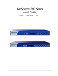
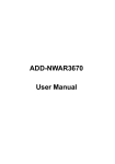
The Front Panel
The information revealed by each LED is as follows:
LED
Purpose
Color
Meaning
Power
Power Status
green
Power is functioning correctly.
off
The device is not receiving power.
red
Critical alarm—failure of hardware component or
software module (such as a cryptographic
algorithm)
amber
Major alarm:
Low memory (<10% remaining)
High CPU utilization (>90%)
Log memory full
Sessions full
Maximum number of VPN tunnels reached
Firewall attacks detected
off
No alarms.
blinking green
Normal operation.
green
Booting up normally.
off
No HA activity has been defined.
green
Port is a master in a redundancy cluster.
amber
Port is a slave in a redundancy cluster.
amber
Session utilization is between 70% and 90%.
red
Session utilization is greater than 90%.
off
Normal operation.
Alarm
Status
HA
Session
Flash
System Alarm
System Status
High Availability
(HA)
Session
Utilization
Compact Flash
green
(CF) Card Status
blinking green
off
NetScreen-50
The card is installed.
Read-write activity is detected.
CF slot is empty.
3
Chapter 1 Overview
Asset Recovery Pinhole
The asset recovery pinhole is a switch that resets the device to its original default
settings. To use this switch, insert a stiff wire (such as a straightened paper clip) into the
pinhole.
Warning: Because resetting the device restores it to the original default configuration, any
new configuration settings are lost, and the firewall and all VPN service become
inoperative.
Console and Modem Ports
The Console port is a RJ-45 serial console port connector, for vt100 terminal emulator
programs to perform local configuration and administration.
The Modem port is a RJ-45 serial console port connector, for establishing remote console
sessions using dialup connections through a 9600 bps RS-232 cable. Dialing into the
modem establishes the dialup console connection.
The table below lists the RJ-45 to DB-9 adapter connection definitions. To employ a
standard UART port, both the console and the modem ports must use this configuration.
DB9
Signal
Abbreviation DTE
DCE
RJ45
1
Data Carrier Detect
DCD
In
Out
NC
2
Received Data
RD
In
Out
3
3
Transmitted Data
TD
Out
In
6
4
Data Terminal Ready
DTR
Out
In
7
5
Signal Ground
SGND
N/A
N/A
4
6
Data Set Ready
DSR
In
Out
2
7
Request To Send
RTS
Out
In
8
8
Clear To Send
CTS
In
Out
1
9
Ring Indicator
RI
In
Out
NC
Compact Flash Card Slot
The Compact Flash slot is for downloading or uploading system software or
configurations. This slot can accept a SanDisk CompactFlashTM card with a variety of
memory capacities. NetScreen has tested 96MB and 512MB cards. The NetScreen device
automatically detects the presence of a flash card and records the system log to it.
4
User’s Guide
The Rear Panel
Ethernet Interfaces
Each Ethernet port is a 10/100 auto-sensing interface. Each port has a pair of LEDs: the
left LED indicates network traffic activity and the right LED indicates if the link is up
(the port is connected to an active device).
THE REAR PANEL
The rear panel of the NetScreen-50 device contains the power outlet and ON/OFF switch.
Power Outlet
ON/OFF Switch
You can order the NetScreen-50 device with either an AC or DC power supply.
NetScreen-50
5
Chapter 1 Overview
6
User’s Guide
2
Chapter 2
Installing the Device
This chapter describes how to install a NetScreen-50 device in an equipment rack or on a
desktop.
Topics in this chapter include:
•
“General Installation Guidelines” on page 8
•
“Equipment Rack Mounting” on page 8
–
“Equipment Rack Installation Guidelines” on page 8
–
“Equipment Rack Accessories and Required Tools” on page 9
–
“NetScreen-50 Rack Mount” on page 9
Note: For safety warnings and instructions, please refer to the NetScreen Safety Guide.
The instructions in this guide warn you about situations that could cause bodily injury.
Before working on any equipment, be aware of the hazards involved with electrical
circuitry and be familiar with standard practices for preventing accidents.
NetScreen-50
7
Chapter 2 Installing the Device
GENERAL INSTALLATION GUIDELINES
Observing the following precautions can prevent injuries, equipment failures and
shutdowns.
•
Never assume that the device is disconnected from a power source. Always check
first.
•
Room temperature might not be sufficient to keep equipment at acceptable
temperatures without an additional circulation system. Ensure that the room in
which you operate the device has adequate air circulation.
•
Do not work alone if potentially hazardous conditions exist.
•
Look carefully for possible hazards in your work area, such as moist floors,
ungrounded power extension cables, frayed power cords, and missing safety
grounds.
•
The product should be installed in a restricted area to prevent personal injury
from exposure to DC voltage.
Warning: To prevent abuse and intrusion by unauthorized personnel, install the
NetScreen-50 device in a locked-room environment.
EQUIPMENT RACK MOUNTING
The NetScreen-50 device comes with accessories for mounting the device in a standard
19–inch equipment rack.
Equipment Rack Installation Guidelines
The location of the chassis, the layout of the equipment rack, and the security of your
wiring room are crucial for proper system operation.
Use the following guidelines while configuring your equipment rack.
8
•
Enclosed racks must have adequate ventilation. Such ventilation requires
louvered sides and a fan to provide cooling air.
•
When mounting a chassis in an open rack, be sure that the rack frame does not
block the intake or exhaust ports. If you install the chassis on slides, check the
position of the chassis when it is seated all the way into the rack.
•
In an enclosed rack with a ventilation fan in the top, equipment higher in the
rack can draw heat from the lower devices. Always provide adequate ventilation
for equipment at the bottom of the rack.
•
Baffles can isolate exhaust air from intake air. The best placement of the baffles
depends on the airflow patterns in the rack.
User’s Guide
Equipment Rack Mounting
Equipment Rack Accessories and Required Tools
Rack mounting requires the following accessories and tools:
•
1 Phillips-head screwdriver (not provided)
•
4 screws to match the rack (if the thread size of the screws provided in the
NetScreen-50 product package do not fit the thread size of the rack)
•
The included rack mount bracket kit.
NetScreen-50 Rack Mount
To rack mount the NetScreen-50 device:
1.
Screw the rack mount brackets to each side of the chassis.
2.
Screw the left and right brackets to the rack, as shown below.
NetScreen-50
9
Chapter 2 Installing the Device
10
User’s Guide
3
Chapter 3
Configuring the Device
This chapter describes how to connect a NetScreen-50 device to your network and perform
initial configuration on the device. Topics in this chapter include:
•
“Operational Modes” on page 12
–
“Transparent Mode” on page 12
–
“Route Mode” on page 12
•
“The NetScreen-50 Interfaces” on page 13
•
“Connecting the Device to a Network” on page 14
•
“Establishing an HA Connection Between Devices” on page 15
•
“Performing Initial Configuration Using the CLI” on page 17
–
“Connecting Using a vt100 Terminal Emulator” on page 17
–
“Setting an IP Address for Managing the Device” on page 18
–
“Connecting Using Telnet” on page 18
–
“Allowing Outbound Traffic” on page 19
–
“Changing Your Admin Name and Password” on page 19
•
“Accessing the Device With the WebUI” on page 20
•
“Asset Recovery” on page 20
–
“Using CLI Commands to Reset the Device” on page 21
–
“Using the Asset Recovery Pinhole to Reset the Device” on page 22
Note: For safety warnings and instructions, please refer to the NetScreen Safety Guide.
The instructions in this guide warn you about situations that could cause bodily injury.
Before working on any equipment, be aware of the hazards involved with electrical
circuitry and be familiar with standard practices for preventing accidents.
Note: You must register your product at www.juniper.net/support/ so that certain ScreenOS
services, such as the Deep Inspection Signature Service, can be activated on the device.
After registering your product, use the WebUI or CLI to obtain the subscription for the
service. For more information about registering your product and obtaining subscriptions
for specific services, see the “System Parameters” chapter in Volume 2 of the NetScreen
Concepts & Examples ScreenOS Reference Guide.
Note: If you access the device for the first time using the ScreenOS WebUI graphical
interface, the Initial Configuration Wizard appears when you log in to the WebUI. This
Wizard guides you through the configuration described in this chapter. For more
information about starting the Initial Configuration Wizard, refer to the Juniper Networks
NetScreen-50 Getting Started Guide.
NetScreen-50
11
Chapter 3 Configuring the Device
OPERATIONAL MODES
The NetScreen-50 device supports two operational modes: Transparent and Route mode.
The default mode is Route.
Transparent Mode
In Transparent mode, the NetScreen-50 device operates as a Layer-2 bridge. Because the
device cannot translate the IP addresses of packets, it cannot perform Network Address
Translation (NAT). Consequently, for the device to access the Internet, any IP address in
your trusted (local) networks must be routable and accessible from untrusted (external)
networks.
In Transparent mode, the IP addresses for Trust and Untrust zones are 0.0.0.0, thus
making the NetScreen device invisible to the network. However, the device can still
perform firewall, VPN, and traffic management according to configured security policies.
Route Mode
In Route mode, the NetScreen-50 device operates at Layer 3. Because you can configure
each interface using an IP address and subnet mask, you can configure individual
interfaces to perform NAT.
•
When the interface performs NAT services, the device translates the source IP
address of each outgoing packet into the IP address of the untrusted port. It also
replaces the source port number with a randomly-generated value.
•
When the interface does not perform NAT services, the source IP address and
port number in each packet header remain unchanged. Therefore, to reach the
Internet your local hosts must have routable IP addresses.
For more information on NAT, see the NetScreen Concepts & Examples ScreenOS
Reference Guide.
Important: Performing the setup instructions below configures your device in Route
mode. To configure your device in Transparent mode, see the NetScreen Concepts &
Examples ScreenOS Reference Guide.
12
User’s Guide
The NetScreen-50 Interfaces
THE NETSCREEN-50 INTERFACES
Each NetScreen-50 device provides Ethernet interfaces for access and connectivity. In
addition, there are logical (non-physical) interfaces that perform special Layer-2 or
management functions.
The configurable interfaces available on a NetScreen-50 device are as follows:
Interface Type
Ethernet interfaces
Description
ethernetn specifies a physical ethernet interface, denoted by a physical port
(n) on the module. Although each interface is bound to a security zone by
default, you can bind it to another zone as required.
• ethernet1 Bound to the Trust zone by default. Connect this interface using
a twisted pair cable with RJ-45 connectors.
• ethernet2 Bound to the DMZ zone by default. Connect this interface using
a twisted pair cable with RJ-45 connectors.
• ethernet3 Bound to the Untrust zone by default. Connect this interface
using a twisted pair cable with RJ-45 connectors.
• ethernet4 Bound to HA zone by default.
Layer-2 interfaces
vlan1 specifies a logical interface used for management and VPN traffic
termination while the NetScreen device is in Transparent mode.
Tunnel interfaces
tunnel.n specifies a logical tunnel interface. This interface is for VPN traffic.
NetScreen-50
13
Chapter 3 Configuring the Device
CONNECTING THE DEVICE TO A NETWORK
The following illustration shows typical cabling for 10/100 Base-T networks. This example
uses the default interface bindings for the Ethernet ports.
Internet
Router
Ethernet Port 3
Ethernet Port 1
To add a NetScreen-50 device to your network:
1.
(Optional) Install the NetScreen-50 device in an equipment rack (see
“Equipment Rack Mounting” on page 8).
2.
Make sure that the power switch on the device is turned OFF.
3.
Connect the power cable, included in the product package, to the NetScreen-50
power outlet at the rear of the device and to a power source.
Warning: To prevent personal injury from exposure to DC voltage, always
replace the insulating cap after installing power cables.
4.
Connect an RJ-45 cross-over cable from the Trust zone interface
(Ethernet port 1) to the internal switch, router, or hub.
Note: Check your router, hub, switch, or PC documentation to see if these devices
require any further configuration. In addition, see if it is necessary to switch OFF
the power to any new device you add to the LAN.
5.
14
Connect an RJ-45 straight-through cable from the Untrust zone interface
(Ethernet port 3) to the external router.
User’s Guide
Establishing an HA Connection Between Devices
6.
Flip the power switch to the ON position.
7.
After the NetScreen-50 device starts, check the following LEDs:
–
The Power LED glows green.
–
The Status LED blinks green.
–
The Ethernet port LEDs for each connected interface glows or blinks
green. (For more details about interpreting the Link Status LEDs, see
“Ethernet Interfaces” on page 5.)
ESTABLISHING AN HA CONNECTION BETWEEN DEVICES
To assure continuous traffic flow in the event of system failure, you can cable and
configure two NetScreen devices in a redundant cluster. The devices propagate all
network, configuration and session information to each other. Should one device fail, the
other takes over the traffic processing.
The following diagram shows a typical HA setup for NetScreen-50 devices.
Internet
Routers
Switch 1
Switch 2
To Untrust interface
Device 1
Device 2
To HA1 to HA2 interfaces
To Trust
interface
To Trust
interface
Switch 3
NetScreen-50
LAN
Switch 4
15
Chapter 3 Configuring the Device
To cable two NetScreen-50 devices together for HA and connect them to the network:
Note: The cabling instructions given below reproduce the configuration shown previously.
However, this is not the only possible HA configuration. In addition, the instructions
assume that all physical ports and interfaces are still set at their default settings. If you
have changed the port and interface configurations, the instructions below might not work
properly.
1.
(Optional) Install the NetScreen-50 devices in an equipment rack (see
“Equipment Rack Mounting” on page 8).
2.
Make sure that all ON/OFF power supply switches are OFF.
3.
Connect the power cables on each NetScreen-50 to a power source.
Note: Whenever you deploy two NetScreen-50 devices in an HA cluster, connect
each to a different power source, if possible. If one power source fails, the other
source might still be operative.
4.
Connect a 10/100 Base-T cable from the HA1 zone interface (Ethernet port 4) on
Device 1 to the HA2 zone interface (Ethernet port 4) on Device 2.
Device 1
5.
On Device 1, connect a crossover cable from the Trust zone interface (Ethernet
port 1) to the switch labeled “Switch 3.”
6.
On Device 1, connect a straight-through cable from the Untrust zone interface
(Ethernet port 3) to the switch labeled “Layer 3 switch 1.”
Device 2
7.
On Device 2, connect a crossover cable from the Trust zone interface (Ethernet
port 1) to the switch labeled “Switch 4.”
8.
On Device 2, connect a straight-through cable from the Untrust zone interface
(Ethernet port 3) to the switch labeled “Layer 3 switch 2.”
Switches
9.
Cable together the switches labeled “Switch 3” and “Switch 4.”
10.
Cable together the switches labeled “Layer 3 switch 1” and “Layer 3 switch 2.”
11.
Cable the switches labeled “Layer 3 switch 1” and “Layer 3 switch 2” to routers.
Note: The switch ports must be defined as 802.1Q trunk ports, and the external
routers must be able to use either Hot Standby Router Protocol (HSRP) or Virtual
Router Redundancy Protocol (VRRP). For the best configuration method, see the
documentation for your switch or router.
12.
Turn the power switches for all devices ON.
For more advanced HA configurations, see the NetScreen Concepts & Examples ScreenOS
Reference Guide.
16
User’s Guide
Performing Initial Configuration Using the CLI
PERFORMING INITIAL CONFIGURATION USING THE CLI
There are two ways to establish a console session with the NetScreen-50 device:
•
Using a vt100 terminal emulator, such as Hilgraeve® Hyperterminal®, through
an RJ-45 serial cable connected to the console port.
•
Using Telnet through a TCP/IP network connection to the NetScreen-50 device.
Connecting Using a vt100 Terminal Emulator
To establish a connection to the NetScreen-50 device using a vt100 Terminal Emulator:
1.
Connect an RJ-45 serial cable between the console port on the NetScreen-50
device and the serial port on your PC.
2.
Start the vt100 terminal emulator program on your PC.
Typical settings for a console session are as follows:
• Baud Rate to 9600
• Parity to No
• Data Bits to 8
• Stop Bit to 1
• Flow Control to none
3.
Press the ENTER key to see the login prompt.
4.
At the login prompt, type netscreen.
5.
At the password prompt, type netscreen.
Note: Use lowercase letters only. Both login and password are case-sensitive.
6.
(Optional) By default, the console times out and terminates automatically after
10 minutes of idle time. To change the timeout value, execute the following
command:
set console timeout number
where number is the length of idle time, in minutes, before session termination.
To prevent automatic termination, specify a value of zero.
NetScreen-50
17
Chapter 3 Configuring the Device
Setting an IP Address for Managing the Device
The default IP address for managing the NetScreen-50 device through the Trust zone
interface (Ethernet port 1) is 192.68.1.1. This is the IP address that you use to manage the
device through a Telnet session or with the WebUI management application. If you do not
wish to use this default IP address, you need to assign a new one.
To set the IP address of the NetScreen-50 Trust zone interface:
1.
Choose an unused IP address within the current address range of your Local
Area Network.
2.
Set the IP address of the Trust zone interface to this unused IP address by
executing the following command:
set interface ethernet1 ip ip_addr/mask
For example, to set the IP address and subnet mask of the Trust zone interface
to 10.100.2.183 and 16, respectively:
set interface ethernet1 ip 10.100.2.183/16
3.
To confirm the new port settings, execute the following command:
get interface
You should see that the IP address for the Trust zone interface is the IP address
you set.
Connecting Using Telnet
To establish a Telnet session with the NetScreen-50 device:
1.
Connect an RJ-45 cross-over cable from the Trust zone interface on the
NetScreen-50 device to the internal switch, router, or hub in your LAN (see
“Connecting the Device to a Network” on page 14).
2.
Open a Telnet session, specifying the current IP address for the Trust zone
interface. For example, in Windows, click Start >> Run, enter telnet ip_addr
(where ip_addr is the address of the Trust zone interface), and then click OK.
For example, if the IP address of the Trust zone interface is 10.100.2.183, enter:
telnet 10.100.2.183
18
User’s Guide
Performing Initial Configuration Using the CLI
3.
At the Username prompt, type netscreen.
4.
At the Password prompt, type netscreen.
Note: Use lowercase letters only. Both Username and Password are casesensitive.
5.
(Optional) By default, the console times out and terminates automatically after
10 minutes of idle time. To change the timeout value, execute the following
command:
set console timeout number
where number is the length of idle time, in minutes, before session termination.
To prevent automatic termination, specify a value of 0.
Allowing Outbound Traffic
By default, the NetScreen-50 device does not allow inbound or outbound traffic, nor does
it allow traffic to or from the DMZ. You need to create access policies to permit specified
kinds of traffic in the directions you want. (You can also create access policies to deny and
tunnel traffic.)
The following access policy permits all kinds of outbound traffic from any point on the
trusted network to any point on the untrusted network.
set policy from trust to untrust any any any permit
Save you access policy configuration with the following command:
save
Important: Your network might require a more restrictive policy than the one created in
the example above. The example is NOT a requirement for initial configuration.
You can also use the Outgoing Policy Wizard in the WebUI management application to
create access policies for outbound traffic. See “Accessing the Device With the WebUI” on
page 20 for information on accessing the WebUI application.
Changing Your Admin Name and Password
Because all NetScreen products use the same admin name and password (netscreen), it
is highly advisable to change your admin name and password immediately. Enter the
following commands:
set admin name name_str
set admin password pswd_str
save
For information on creating different levels of administrators, see “Administration” in the
NetScreen Concepts & Examples ScreenOS Reference Guide.
NetScreen-50
19
Chapter 3 Configuring the Device
ACCESSING THE DEVICE WITH THE WEBUI
To access the NetScreen-50 device with the WebUI management application:
1.
Connect your PC (or your LAN hub) to the Trust zone interface, as described in
“Connecting the Device to a Network” on page 14.
2.
Launch your browser, enter the IP address of the Trust zone interface in the
URL field, and then press Enter.
For example, if you assigned the Trust zone interface of the device the IP
address of 10.100.2.183/16, enter the following:
10.100.2.183
The NetScreen WebUI software displays the login prompt.
3.
Enter netscreen in both the Admin Name and Password fields, then click
Login. (Use lowercase letters only. The Admin Name and Password fields are
both case sensitive.)
The NetScreen WebUI application window appears.
Note: NetScreen-Security Manager 2004 (NSM) and NetScreen Rapid
Deployment (RD): If you are using NSM, you can optionally configure NetScreen
appliances with RD. Refer to the Rapid Deployment Getting Started Guide for
more information.
ASSET RECOVERY
If you lose the admin password, you can use one of the following procedures to reset the
NetScreen device to its default settings. This destroys any existing configurations, but
restores access to the device.
Warning: Resetting the device will delete all existing configuration settings, and the
firewall and VPN service will be rendered inoperative.
20
User’s Guide
Asset Recovery
Note: After you successfully reset and reconfigure the NetScreen device, you should back up
the new configuration setting. As a precaution against lost passwords, you should back up
a new configuration that contains the NetScreen default password. This will ensure a
quick recovery of a lost configuration. You should change the password on the system as
soon as possible.
Using CLI Commands to Reset the Device
To perform this operation, you need to make a console connection, as described in
“Connecting Using a vt100 Terminal Emulator” on page 17.
Note: By default the device recovery feature is enabled. You can disable it by entering the
following CLI command: unset admin device-reset.
1.
At the login prompt, type the serial number of the device.
2.
At the password prompt, type the serial number again.
The following message appears:
!!! Lost Password Reset !!! You have initiated a command to reset the device to
factory defaults, clearing all current configuration and settings. Would you like to
continue? y/[n]
3.
Press the y key.
The following message appears:
!! Reconfirm Lost Password Reset !! If you continue, the entire configuration of
the device will be erased. In addition, a permanent counter will be incremented to
signify that this device has been reset. This is your last chance to cancel this
command. If you proceed, the device will return to factory default configuration,
which is: System IP: 192.168.1.1; username: netscreen; password: netscreen.
Would you like to continue? y/[n]
4.
Press the y key to rest the device.
You can now login in using netscreen as the default username and password.
NetScreen-50
21
Chapter 3 Configuring the Device
Using the Asset Recovery Pinhole to Reset the Device
You can also reset the device and restore the factory default settings by pressing the asset
recovery pinhole. To perform this operation, you need to make a console connection, as
described in “Connecting Using a vt100 Terminal Emulator” on page 17.
1.
Locate the asset recovery pinhole on the front panel. Using a thin, firm wire
(such as a paper clip), push the button located behind the asset recovery pinhole
for four to six seconds.
Asset Recovery Pinhole
A serial console message states that the “Configuration Erasure Process has
been initiated” and the system sends an SNMP/SYSLOG alert. The Status LED
blinks amber once every second.
After the first reset is accepted, the power LED blinks green. The serial console
message now reads, “Waiting for 2nd confirmation.”
2.
Release the button for one second.
3.
Push the button again for four to six seconds. A serial console message states
“Second push has been confirmed.”
The Status LED lights amber for one-half second, then returns to the blinking
green state. Continue to press the button until the message “Configuration
Erase sequence accepted, unit reset.” The system generates SNMP and SYSLOG
alerts to configured SYSLOG or SNMP trap hosts.
Note: During a reset, there is no guarantee that the final SNMP alert sent to the
receiver before the reset will be received.
4.
Release the button.
5.
The device now erases the configuration and restarts.
If you do not follow the complete sequence, the reset process cancels without any
configuration change and the serial console message states, “Configuration Erasure
Process aborted.” The status LED returns to blinking green. If the unit did not reset, an
SNMP alert is sent to confirm the failure.
22
User’s Guide
4
Chapter 4
Replacing the Fuse
The NetScreen-50 device uses a 2.5 Amp slow-blow fuse rated for 250 Volts.
To replace a failed fuse on the NetScreen-50 device:
1.
Take the device off-line, turn the power switch OFF, and disconnect the power
cable.
2.
Using a screwdriver, separate the lid of the external fuse cover from the surface
of the power outlet.
3.
Manually remove the fuse assembly from the device.
4.
To replace the fuse assembly, enter the new fuse into the opening and slide it in
until the fuse clicks into place.
5.
Replace the power cable and turn the device power switch ON. Reconnect the
network cables.
NetScreen-50
23
Chapter 4 Replacing the Fuse
24
User’s Guide
Appendix A
Specifications
A
This appendix provides general system specifications for the NetScreen-50 device.
•
“NetScreen-50 Attributes” on page A-II
•
“Electrical Specification” on page A-II
•
“Environmental” on page A-II
•
“Safety Certifications” on page A-II
•
“EMI Certifications” on page A-II
•
“Connectors” on page A-III
NetScreen-50
A-I
Appendix A Specifications
NETSCREEN-50 ATTRIBUTES
Height: 1.73 inches (4.4 cm)
Depth: 10.8 inches (27.4 cm)
Width: 17.5 inches (44.5 cm)
Weight: 8 pounds (36 Hg)
ELECTRICAL SPECIFICATION
AC voltage: 100-240 VAC +/- 10%
DC voltage: -36 to -60 VDC
Maximum AC Watts: 45 Watts
Maximum DC Watts: 50 Watts
Fuse Rating: 2.5 Amp / 250 Volts
ENVIRONMENTAL
Temperature
Operating
Normal altitude
32-105° F, 0° -40° C
Relative humidity
10-90%
Non-condensing
10-90%
The maximum normal altitude is 12,000 ft. (0-3,660 m)
SAFETY CERTIFICATIONS
UL, CUL, CSA, CB, Austel, ICE 60950
EMI CERTIFICATIONS
FCC class A, BSMI, CE class A, C-Tick, VCCI class A
A-II
User’s Guide
Connectors
CONNECTORS
The RJ-45 twisted-pair ports are compatible with the IEEE 802.3 Type 10/100 Base-T
standard. The following table describes the media type and distance for these connectors.
Standard
Media Type
100Base-TX
Category 5 and higher Unshielded Twisted Pair (UTP)
Cable
NetScreen-50
Mhz/Km
Rating
Maximum
Distance
100 m
A-III
Appendix A Specifications
A-IV
User’s Guide
Index
Index
A
HA 3
power 3
session 3
status 3
asset recovery 20
C
cables
RJ-45 connectors 4, 13
twisted pair 13
cabling, power supply 16
connecting network interfaces 14, 18
connecting power 14
console
changing timeout 17, 19
initiating a session 17
console port 4
G
M
management software, logging on 20
N
NetScreen publications vi
P
password
changing 19
resetting 20
ports, console 4
guide organization v
H
HA connection 16
I
installation guidelines 8
R
rack
installation guidelines 8
mounting 8
reset 20
T
L
transparent mode 12
LEDs
alarm 3
Flash 3
V
NetScreen-50
ventilation 8
IX-1
Index
IX-2
User’s Guide