1
AVID ZR & ZR Plus Position Monitors
Installation & Operating Instructions
AVID
Installation and operating instructions for AVID ZR &
ZR Plus, Corrosion resistant ATEX approved position
monitors for General Purpose, Hazardous Area and
Intrinsically Safe Applications
ZR Position
Monitor
Note
All AVID® Products are factory equipped with Pentair direct mounting. For standard Namur
mounting see Appendix “A”. Please ensure that the Pentair/Keystone actuator is provided with the
standard 16 dia x 11 af drive.
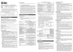
1. Operate the actuator to full closed position.
ModMount
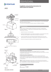
2. Fasten the ZR Position Monitor to the actuator using (4) M5 x 12 mm long socket head cap
screws and (4) M5 washers while engaging its output shaft into the actuator’s input (fig.1).
3. Loosen the (4) captive screws which fasten the ZR Position Monitor cover. Twist cover
approximately 45° and lift up (fig.2). (Wiring diagram inside ZR Position Monitor cover).
Actuator
4. To set switches, lift bottom cam and turn until closed switch is activated and then release.
Spring will push cam back onto the splined shaft. Operate the actuator to the opposite
extreme, push down on the top cam and turn until the open switch is activated (fig. 3).
Figure 1
5. Operate actuator from one extreme to the other several times to check switch operation.
Twist cover 45°
then lift straight up
6. Replace housing cover. Confirm that you have noted the final position of the valve, (full open
or full closed).
7. Make sure the HiVue visual display coincide with the position of the valve (fig.4).
8. The inner HiVue indicator should show either “Open” or “Closed. If the position indicated is
the opposite of the actuator position. Remove the outer indicator by removing the four (4) slot
head screws and rotate the inner indicator 90° to correct the visual display.
9. Secure the outer HiVue indicator to the housing cover with (4) slot head screws.
10. Ensure the correct gland is installed to provide the appropriate rating.
Figure 2
Top Cam
Push down
turn & release
Important: Do not exceed 1.13 Nm of torque for each screw
HiVue
Bottom Cam
Valve open
Lift up
turn & release
Figure 3
www.pentair.com/valves
Valve closed
Figure 4
Pentair reserves the right to change the contents without notice
AVDSB-0029-EN-1305
AVID ZR & ZR Plus Position Monitors
Installation & Operating Instructions
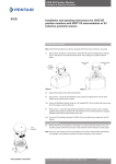
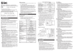
Exploded parts list
ZR & ZR Plus parts description
Item # Qty
Description
11Housing Assembly
21Shaft Assembly
31Cover Assembly
4
1
Direct Mount Assembly
5
1
RFX Coil Assembly (note 1)
6
1
RFX Solenoid Valve
Assembly (note 1)
3
Note 1
Items 5 & 6 are supplied with ZR Plus Control
Position Monitors, only.
2
1
5
6
4
Pentair reserves the right to change the contents without notice
page 2
AVID ZR & ZR Plus Position Monitors
Installation & Operating Instructions
Technical data
V3 Mechanical Switches
Electrical Version SPDT form C
Electrical Rating 15 amps/125/250 VAC
6 amps/24 VDC
0.5 amps/125 VDC
0.25 amps/250 VDC
Proximity Type (Inductive), Intrinsically Safe
Sensing Range
Electrical Version Hysteresis
Nominal Voltage Input Voltage Range Output Load Current 2 mm
D.C. voltage 2 wire in accordance DIN19234 (NAMUR)
Approx. 5%
8 VDC
5-25 VDC
(Target Present) ≤ 1mA
(Target Absent) ≥ 3mA (15 mA Max.)
Optional Proximity Type (Inductive)
The ZR position monitor is also available with 2 & 3-wire DC PNP/NPN (NO/NC) inductive
proximity sensors (5-36 VDC) and 2-wire AC/DC inductive proximity sensors
(20-140 AC/ 10-140 DC).
T Sensor for EEx m e Classification
Electrical Version
SPDT Form C
Normally Open
ContactsRhodium
Electrical Rating
2A / 120VAC
1.5A / 24VDC
1.0A / 230VAC
Contact Resistance
0.08 Ohms
SealEncapsulation
Materials of Construction
Housing
Cover Shaft Fasteners HiVue ModMount Engineered Resin
Clear Engineered Resin
Stainless Steel
Stainless Steel
Copolyester
Engineered Resin
Area Classification & Approvals
WeatherproofIP67
ATEX
II 2 G / 3 D EEx ia II C T 6
II 2 G / 3 D T80°C EEx me II T 6
Enclosure
Conduit Entries
Temperature Range
ZR with V3 Mech
ZR Plus with V3 Mech
ZR with NJ2-V3-N
Temperature Rating
2 x M20
2 x 1/2” NPT
2 x PG 13.5
-40°C to +80°C
-40°C to +80°C
-25°C to +80°C
-40°C to +150°C
Appendix “A”
Instructions for ZR & ZR Plus Mounting Using Standard Namur Output:
1.Remove Pentair direct mounting bracket assembly from the ZR or ZR Plus position monitor.
Note: The ZR & ZR Plus position monitor comes with a standard Namur output shaft.
2.Replace bracket assembly with a standard Namur mounting bracket.
Note: Standard Namur mounting bracket is not included.
Pentair reserves the right to change the contents without notice
page 3
AVID ZR & ZR Plus Position Monitors
Installation & Operating Instructions
Dimensions (mm) - ZR Position Monitor - Pentair Direct Mounting
59Dia.
54
133
M20
PG 13.5
1/2” NPT
(2 places)
151
98.8
67
ModMount
130
Actuator
108
19
11
Side View
Top View
Standard Pentair/Keystone output shaft
40,1 CRS
93,5 CRS
M5 Clearance Holes
19.0
ø 16.0
11.0 Flat
Dimensions (mm) - ZR Plus Position Monitor - Pentair Direct Mounting
1/4” NPT
G1/4 ISO 228
59Dia.
M20
PG 13.5
1/2” NPT
(2 places)
54
165
88.6
72.9
35
151
133
50.8
98.8
67
38.4
28.7
ModMount
Actuator
130
108
19
11
Side View
Top View
Standard Pentair/Keystone output shaft
40,1 CRS
93,5 CRS
M5 Clearance Holes
19.0
ø 16.0
11.0 Flat
Pentair reserves the right to change the contents without notice
page 4
AVID ZR & ZR Plus Position Monitors
Installation & Operating Instructions
Note
All ZR Plus units are factory installed with a solenoid valve. No internal installation is required.
General Description
The solenoid valve incorporates elastomer static seals through which a shaped spool moves
which are designed for 5 way operation. 5 way valves are normally used to control the action of
double acting cylinders.
The seal spacer assembly forms individual annular chambers opposite each valve port and the
grooved spool either closes or allows flow between adjacent chambers. The position of the spool
determines which ports are open or closed.
The spool is moved by way of a manually or mechanically operated mechanism normally against
a return spring. Operation may be by application or removal of a pilot air supply acting on a pilot
piston. This form of control is utilized for electrical actuation where integral solenoid valves control
the pilot air supply.
Specifications
Operating Pressure
Operating Temperature
Operating Media
45-120 PSIG
-20° C to +65° C (I/S only)
-20° C to +82° C
Non Lubricated Filtered Air to 20 Microns
Field Wiring
Complete the electrical wiring in accordance with local and National Electrical Codes. The ground
wire should be secure under the green screw. Check all screws for tightness. If the installation is in
a hazardous area, all electrical leads must be sealed with an approved compound, in accordance
with local and National Electrical Codes unless the switches are hermetically sealed. (NEC 5051-5)
Always check the nameplate to make sure the approval ratings coincide with the application.
CAUTION
To prevent ignition of hazardous atmospheres, replace cover before actuating the electrical
circuits. Keep cover tightly closed when in operation.
(Air Line) Designation
1/4” NPT or 1/4” BSP air ports for inlet, outlet, and exhaust
Description of Operation
Solenoid De-energized air flows from Inlet Port 1 to Port 2 and exhausts from Port 4
to Port 5.
Solenoid Energizedair flows from Inlet Port 1 to Port 4 and exhausts from Port 2
to Port 3.
(Air Line) Installation Considerations
Air Mains and lines should be large enough to avoid excessive pressure loss under conditions
of maximum flow. Air lines should be installed with as few restrictions as possible if the cost of
compressed air is to be kept to a minimum. Sharp turns in piping should be avoided for more
efficient air flow and economical air power. It is advisable to pitch the mains in the direction of air
flow so that both gravity and air flow will carry the water to traps or water legs located at frequent
intervals.
To help in preventing condensed moisture from reaching the point of usage, down pipes should
never be taken directly from the bottom of air pipes or mains. Connection should be made at the
top of the main and a long radius return bend used.
Air Flow
Pipe sizes are normally determined on semi empirical lines, basis for selection being an acceptable
pressure drop e.g. not more than 10% of the applied pressure. In sizing pipes, consideration
should be given to likely future demands, as a system will be inefficient if the demand outgrows
the supply. It is always better to over size mains as this will reduce air velocity and make water
separation more effective.
Air Service Equipment
The importance of proper filtration (20 Micron) and lubrication of the air supply to pneumatic
equipment can never be over-emphasized as a means of decreasing friction and preventing
corrosion and wear due to moisture and abrasive solids being present in the air supply. At higher
pressures than recommended, pneumatic equipment can wear excessively with no significant
increase in output and compressed air is consequently wasted.
There is much to be gained, therefore, from providing pneumatic equipment with serviced air by
including suitable air line filters, pressure regulators and lubricants in the installation.
Pentair reserves the right to change the contents without notice
page 5
AVID ZR & ZR Plus Position Monitors
Installation & Operating Instructions
Tubes and Fittings
The use of copper,stainless steel, nylon or polyethylene tube is recommended for piping up air
circuits and equipment. As a general rule, pipe threaded fittings should not be assembled to a
specific torque because the torque required for a reliable joint varies with thread quality, port
and fitting materials, sealant used, and other factors. The suggested method of assembling
pipe threaded connections is to assemble them finger tight and then wrench tighten further to a
specified number of turns from finger tight. The assembly procedure given below is for reference
only, the fitting should not be over tightened for this will lead to distortion and most likely,
complete valve failure.
1.Inspect port and connectors to ensure that the threads on both are free of dirt, burrs and
excessive nicks.
2.Apply sealant/lubricant or Teflon tape to the male pipe threads. With any sealant tape, the first
one or two threads should be left uncovered to avoid system contamination.
3.Screw the connector into the port to the finger tight position.
4.Wrench tighten the connector approximately 1 - 2 turns (to seal) from finger tight. Again this is
only reference - the fitting should NOT be over tightened.
Maintenance
Routine maintenance is usually confined to the periodic replenishment of Dow Corning III lubricant
or equivalent to spool and spring.
Coil Replacement
1. Verify that the electrical power to the coil is off.
2. Carefully remove the clear exhaust tube from the fitting by sliding each collar to the middle of
the tube and then sliding the tube off of the barbed ends.
3. Remove the coil leads from the terminal block, noting terminal connections.
4. Note the wire route of the coil leads and cut the wire tie that holds the coil leads to the
terminal post.
5. Loosen and remove the coil retaining nut.
6. Turn the coil 90° so the leads are positioned from the top of the coil to the side and slide the
coil off of the core tube.
7. With the coil leads positioned to the right of the coil (as in Step 6), slide the replacement
coil over the core tube until it bottoms. The lettering on the coil should be right side up with
respect to the valve body.
8. Install the new coil retaining nut until it is “hand tight”.
9. Route the coil lead wires as before insuring sufficient clearance for moving parts, and using
the replacement wire tie, affix the coil leads to the terminal post.
10. Following the wiring diagram on the inside of the cover assembly, insert and fasten coil lead
wires into the terminal block. Ensure that bare wires are clamped.
11. Re-install the clear exhaust tube over the barbed fittings making sure the collars are secure
behind the barbed recess.
Valve Replacement
1.
2.
3.
4.
5.
6.
7.
8.
Verify that the electrical power to the coil and air supply to the valve as both off.
Remove all piping from the valve assembly.
Remove the coil as described above in the “Coil Replacement” procedure steps 1-6.
Note: If the coil is not to be replaced, skip steps 3 & 4.
Remove the barbed fitting from the bottom of enclosure if damaged.
Remove the valve retaining nut and lock washer from the valve assembly.
Remove the valve assembly from the conduit entry.
Verify that the o-ring is in position on the replacement valve assembly.
Pass the core tube through the conduit entry and position the valve as desired (increments
of 90°). Verify that the locating pins are completely inserted into the locating holes on the
enclosure.
9. Replace the lock-washer and valve retainer nut and tighten until lock-washer is flat.
10. Replace the coil as described above in the “Coil Replacement” procedure, steps 7-11.
11. Reinstall the piping to the valve assembly.
Pentair reserves the right to change the contents without notice
page 6
Namur shaft details