1
AVID XA+ Control Position Monitor
Installation & Operating Instructions
AVID
Installation and operating instructions for AVID XA+
Control Position Monitor for hazardous applications
according product certification:
xxxx
II 2GD
EPSILON 08 ATEX 2434X
Ex d IIB +H2 T* Tamb -*°C to +*°C
Ex tD A21 IP6X T*°C Tamb -*°C to +*°C
Beacon cover -30°C to +85°C (T4); -30°C to +75°C (T5); -30°C to +60°C (T6)
Environmental parameters: 80 kPa (0.8 bar) to 110 kPa (1.1 bar). Air with normal oxygen content,
typically 21%.
1 Product description
The XA+ series valve control monitor has an integral solenoid coil that can be used with various
solenoid configurations such a 3/2 and 5/2 way valves.
The XA+ also provides two methods of end of travel indication by the means of mechanical
switches, inductive proximity sensors or proximity switches and an external visual indicator.
For applications that require position feed back, ancillary components such as a 4-20 mA current
signal transmitter or a resistive signal feed back can be installed.
To allow this product to be used with network communication bus protocols, the XA+ series
enclosure can house various network modules.
The XA+ series enclosure comprises of a two parts, a cover and housing. The housing can offer up
to four of the following conduit entries; M20 x 1.5p, M25 x 1.5p, 1/2”-14 NPT or 3/4”-14 NPT cable
entries for connection to an external power source via appropriate ATEX certified cable glands. The
XA+ certification is compliant against the following standards:
EN 60079-0 : 2006
EN 60079-1 : 2007
EN 61241-0 : 2006
EN 61241-1 : 2006
Electrical apparatus for explosive gas atmospheres –
Part 0 - General requirements
Electrical apparatus for explosive gas atmospheres –
Part 1 - Flameproof enclosures ‘d’
Electrical apparatus for use in the presence of combustible dust –
Part 0 - General requirements
Electrical apparatus for use in the presence of combustible dust –
Part 1 - Protection by enclosures ‘tD’
Note: Before installation of this product, please ensure that the product and its certification is
suitable for the intended application. If the equipment is likely to come into contact with aggressive
substances, then it is the responsibility of the user to take suitable precautions that prevent it from
being adversely affected, thus ensuring that the type of protection provided by the equipment is
not compromised.
Installation of any cable entry devices, conduit entry devices or blanking devices shall not
compromise the degree of ingress protection level IP6X for use in the presence of combustible
dusts.
The unit has an ingress protection of IP66 / 67 and therefore any conduit device fitted must
maintain this.
Note: These products have been certified with a cable entry temperature rise of 4°C. Ensure that
this is taken into consideration when selecting suitable cabling for the ambient temperature in
which the product is to be used.
Note: These products are not intended to be assembled directly to process pipe work etc that is
heated or cooled to temperatures outside of the range as indicated above.
www.pentair.com/valves
Pentair reserves the right to change the contents without notice
AVDSB-0032-EN-1305
AVID XA+ Control Position Monitor
Installation & Operating Instructions
XA+ position
monitor
Warning
Do not open when energised or when an explosive atmosphere is present.
Warning
Mounting
bracket
assembly
Electrostatic hazard, clean only with damp cloth.
Actuator
2 Mounting instructions
2.1
2.2
The XA+ housing is assembled with the Pentair ModMount adapter (standard). To
re-orientate the ModMount, if required, loosen and remove the four M8 socket head cap
screws, position the bracket and replace the screws.
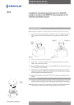
Figure 1
To ensure that the XA+ series drive coupler is orientated correctly, it may be necessary to
stroke the actuator to the fully closed position.
Warning
Before stroking the actuator to the fully closed position, please ensure that the process is
safe to do so.
2.3
With the actuator in the correct position, attach the XA+ series bracket to the actuator using
the hardware provided in the mounting kit.
2.4
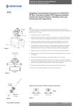
To release the cover, loosen the cover retaining screws. Twist the cover approx 45° and lift
up. See Fig 1.
2.5
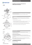
To set the switches, stroke the actuator to its close position, lift the bottom cam and turn
until the switch has activated and then release. The spring will push the cam back onto the
splined shaft.
Warning
Before stroking the actuator, please ensure that the process is safe to do so and that all
hands are kept away from the moving shaft.
Twist cover 45°
then lift straight up
Figure 2
2.6 Stroke the actuator to the open position. Set the top cam by pushing down and turning the
cam until the switch is activated.
Warning
Before stroking the actuator, please ensure that the process is safe to do so and that all
hands are kept away from the moving shaft.
2.7
Stroke the actuator from one end of stroke to the other several times to check the switch
operation. If the switches require adjustment, repeat steps 2.5 to 2.7.
2.8
Replace the housing cover and secure the (4) captive screws. Confirm that you have noted
the final position of the valve (full open or full closed).
Top Cam
Push down
turn & release
Figure 3
Pentair reserves the right to change the contents without notice
page 2
Bottom Cam
Lift up
turn & release
AVID XA+ Control Position Monitor
Installation & Operating Instructions
3 Field wiring & installation
Warning
The XA+ series should always be handled with care when the cover is removed
and wired to electrical power source.
Note:Before electrical installation, please read and follow the wiring diagram located
inside the cover. The electrical ratings can be found on the product I.D label.
3.1
Field wiring must be carried out in accordance with site, local and national electrical codes /
requirements. This includes special attention to earth bond to the aluminium enclosure using
the internal and external earth points provided.
3.2
Installation of this product shall be carried out by competent personnel in accordance with
the applicable code of practice such as EN60079-14.
3.3
The XA+ position monitor housing can offer up to three of the following conduit entries;
M20 x 1.5p, M25 x 1.5p, 1/2”-14 NPT or 3/4”-14 NPT. These entries are detailed on the
product I.D label found on the product cover. Please see Fig. 4 for conduit positions.
Conduit B
Conduit C
Conduit D
Figure 4
Conduit A
Always used with
M32 Ex d coil
3.4
The certification applies to equipment without cable glands. When mounting the flameproof
enclosure in the hazardous area, only suitably rated IP 66 / 67 ATEX certified flameproof
glands must be used.
3.5
All unused cable entries must be plugged with a suitably rated IP 66 / 67 ATEX certified
blanking devices.
3.6
The XA+ is available with a selection of switches and sensors.
Mechanical V3 SPDT switches
Mechanical DPDT switches
Proximity T-switch
Inductive Proximity Sensors
CS 4-20 mA Transmitter
RS Transmitter
Network Fieldbus Options
15 A - 125 or 250 V AC; 0.5 A - 125 V DC; 0.25 A - 250 V DC
10 A - 125 or 250 V AC; 10 A - 28 V DC; 0.2 A - 125 V DC
1 A - 250 V AC; 2 A - 120 V AC or 1.5 A - 24 V DC
Various inductive proximity sensors that can be assembled into the Ex d enclosure.
Various switches / sensors option can be assembled with transmitter.
The CS Transmitter electrical ratings are – current loop 4-20 mA at 18 to 24 V DC.
Various switches / sensors option can be assembled with transmitter.
The RS Transmitter electrical ratings are – 1 K Ohms (standard).
Pentair reserves the right to change the contents without notice
page 3
AVID XA+ Control Position Monitor
Installation & Operating Instructions
Netpak Fieldbus Option
AS-I Actuator Sensor Interface
Device Net
Foundation Fieldbus
Modbus
Profibus DP
Electrical Parameters
24 V DC, 140 mA MAX
24 V DC, 105 mA MAX
9-32 V DC, 34 mA MAX
24 V DC, 85 mA MAX
24 V DC, 120 mA MAX
Note:The data signifies the maximum electrical rating of the product, suitable overloading
protection must be provided to prevent these values being exceeded.
3.6
The XA+ is available with the following coil options:
24 V DC
120 V AC
240 V AC
3.7
The XA+ series enclosure. The table below details the applicable ambient ranges;
Cover Type
Beacon
Beacon
Beacon
3.8
T Class
Ambient Range
T6 (80°C)-30°C - +60°C
T5 (95°C)-30°C - +75°C
T4 (130°C)-30°C - +85°C
Before replace the enclosure cover, ensure that both of the housing and cover flange
surfaces are clean and undamaged. Tighten the cover screws hand tight using a standard
6 mm A/F Allen key ensuring there are no gaps.
4 Product repair & service
4.1
Inspection of this product shall be carried out by suitably trained personnel in accordance
with the applicable code of practice such as EN60079-17.
4.2
In the event of any repairs that may be required such tasks must be carried out by suitably
trained / competent personnel in accordance with the applicable code of practice such as
EN60079-19.
4.3
The certification of this product has been approved based on the material of construction as
per the drawings listed in the schedule within this certificate. Any replacement parts that are
not made in accordance to the listed drawing will invalidate the approval / certification.
4.4
Replacement parts must be purchased through Pentair Valves & Controls or via an approved
Pentair Valves & Controls distributor.
5 Operating and maintenance instructions for Falcon II solenoid valve
5.1
General description
5.1.1 The Falcon II solenoid valve incorporates elastomer static seals through which a shaped
spool moves and are manufactured for 3 or 5 way operation. 3 way is normally used for
pilot control of the other relay valves or for the operation of single acting cylinders. 5 way is
normally used to control the action of double acting cylinders. 3 way operation is realised by
blocking output 4 with a plug.
The seal spacer assembly forms individual annular chambers opposite each valve port and
the grooved spool either closes or allows flow between adjacent chambers, hence the
position of the spool determines which ports are open or closed.
The spool is moved by way of a manually or mechanically operated mechanism normally
against a return spring. Operation may be by application or removal of a pilot air supply
acting as a pilot piston. This form of control is utilized for electrical actuation where integral
solenoid valves control the pilot air supply.
Pentair reserves the right to change the contents without notice
page 4
AVID XA+ Control Position Monitor
Installation & Operating Instructions
5.1.2 Optional features - Falcon II
A
C
B
D
5.1.2.1 Momentary Override
Spring return momentary push type, must hold in to actuate. See Fig. 5A
5.1.2.2 Manual Locking Override
Manually depress palm button and rotate clockwise for maintained condition, must manually
disengage to return to original position. See Fig. 5B
5.1.2.3 No-Voltage Release (Latching)
With the coil first energized, the palm button is then manually moved and latched.
The inward movement of the palm button causes the valve to shift.
When the coil is de-energized, the palm button and latching mechanism are automatically
tripped, allowing the valve to return to its original position. See Fig. 5C
5.1.2.4 Hex Drive Maintained Override
Insert Allen key in hex head screw and rotate clockwise (4-5 turns) to shift spool. Valve
will stay put until hex head screw is rotated counter clockwise (4-5 turns) back to original
position. See Fig. 5D
Figure 5
5.1.3Specifications
Operating pressure: 45 - 120 psig / 3.1 - 8.2 bar
Operating media: Non lubricated filtered air to 20 microns
5.1.4 Field wiring
Complete the electrical wiring in accordance with national and local electrical requirements.
The ground wire should be secure under the green screw. Check all screws for tightness.
A
B
Spring Return valve
Description of operation:
Spring Return valve
Description of operation:
Dual Coil valve
Description of operation:
Solenoid de-energized - air flows from
Outlet Port 2 to Exhaust Port 3.
Solenoid de-energized - air flows from
Inlet Port 1 to Outlet Port 2 and exhausts
from Port 4 to Port 5.
Coil B de-energized - air flows from Inlet
Port 1 to Outlet Port 2 and exhausts from
Port 4 to Port 5.
Solenoid energized - air flows from Inlet
Port 1 to Outlet Port 4 and exhausts from
Port 2 to Port 3.
Coil A energized - air flows from Inlet Port
1 to Outlet Port 4 and exhausts from Port
2 to Port 3.
Solenoid energized - air flows from Inlet
Port 1 to Outlet Port 2.
Figure 6 - Air Line Designation, 1/4” NPT or BSP air ports for inlet, outlet and exhaust
5.1.5 (Air line) Installation considerations
Air mains and lines should be large enough to avoid excessive pressure loss under
conditions of maximum flow. Air lines should be installed with as few restrictions as possible
if the cost of compressed air is to be kept to a minimum. Sharp turns in piping should be
avoided for more efficient air flow and economical air power. It is advisable to pitch the
mains in the direction of air flow so that both gravity and air flow will carry the water to traps
or water legs located at frequent intervals.
To help in preventing condensed moisture from reaching the point of usage, down pipes
should never be taken directly from the bottom of air pipes or mains. Connection should be
made at the top of the main and a long radius return bend used.
Pentair reserves the right to change the contents without notice
page 5
AVID XA+ Control Position Monitor
Installation & Operating Instructions
5.1.6 Air flow
Pipe sizes are normally determined on semi empirical lines, basis for selection being an
acceptable pressure drop e.g. not more than 10% of the applied pressure. In sizing pipes,
consideration should be given to likely future demands, as a system will be inefficient if the
demand outgrows the supply. It is always better to over size mains as this will reduce air
velocity and make water separation more effective.
5.1.7 Air service equipment
The importance of proper filtration (20 micron) and lubrication of the air supply to pneumatic
equipment can never be over-emphasized as a means of decreasing friction and preventing
corrosion and wear due to moisture and abrasive solids being present in the air supply.
At higher pressures than recommended, pneumatic equipment can wear excessively with no
significant increase in output and compressed air is consequently wasted.
There is much to be gained, therefore, from providing pneumatic equipment with serviced
air by including suitable air line filters, pressure regulators and lubricants in the installation.
5.1.8 Tubes and fittings
The use of copper, stainless steel, nylon or polyethylene tube is recommended for piping up
air circuits and equipment. As a general rule, pipe threaded fittings should not be assembled
to a specific torque because the torque required for a reliable joint varies with thread
quality, port and fitting materials, sealant used, and other factors. The suggested method
of assembling pipe threaded connections is to assemble them finger tight and then wrench
tighten further to a specified number of turns from finger tight.
The assembly procedure given below is for reference only, the fitting should not be over
tightened for this will lead to distortion and most likely, complete valve failure.
1. Inspect port and connectors to ensure that the threads on both are free of dirt, burrs and
excessive nicks.
2.Apply sealant/lubricant or Teflon tape to the male pipe threads. With any sealant tape, the
first one or two threads should be left uncovered to avoid system contamination.
3.Screw the connector into the port to the finger tight position.
4.Wrench tighten the connector approximately 1 - 2 turns (to seal) from finger tight. again
this is only reference – the fitting should NOT be over tightened.
Parts list
No. Part Name
1. Pilot piston end cap
2. O-Ring
3. Pilot piston
4. O-Ring
5. Valve body
6. O-Ring
7. O-ring
8. Bush
9. Spacer
10. Bush
11. Pilot piston seal
12. Cap screws
13. O-ring
14. O-ring
15. Cap screws
16. Spring end cap
17. Tell-tale cover
18. Spring
19. Tell-tale pin
20. Spool
8
7
6
5
4
2
9
3
14
1
13
15
10
16
11
18
12
17
19
20
Figure 7
Pentair reserves the right to change the contents without notice
page 6
V5243
OZOIN070/00125
V5119
OZOIN070/01062
5/2 V5246
5/3 V5314
OZOIN0070/01062
5/2 V5042 6 off
3/2 V5042 4 off
V5084
5/2 V4734 5 off
3/2 V4734 3 off
V5084
V4163
OSMO4KS40
OZOIN010/0130
OZOIN070/00125
OSMO4KS16
V5244
V5247
V4571
V5026
5/2V5212
3/2 V5313