1
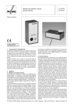
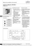
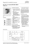
This information is available on the Internet at: www.hansen-neon.de or www.klinger-neon.de
L71/04/2008
Contact: Hansen Neon GmbH, Norderstr. 1, 25855 Haselund, Germany, Tel. +49 4843-2009-0, Fax +49 4843-2009-33, E-mail: [email protected]
Light-dependent Control System
Operating Instructions Part 1
Control Unit
Sensor
Potentiometer P1
Potentiometer P2
2
m
m )
10 H
x x
15 W
x Lx
2 (
.5
m
Service jumper
Ca
ble
~1
230 V input
Sensor connection
0-10 V output
85 x 85 x 40 mm (L x W x H)
Control Elements:
- P1 (brightness): potentiometer for setting the dimming level of the LEDs
- P2 (switch-off): potentiometer for setting the switch-off response characteristic
- Service jumper: for bridging the delay element
Technical Data:
Uoff
= 230 V, 50/60 Hz
I on
= 0.005 A (~1.2 W)
Uoff
= 0–10 V (controlled)
Sensor
Control
unit
Degree of protection = IP54
230 V
Control voltage
0-10 V
Wiring:
230 V
C100/990
230 V
Dimmer 90 W
LED Tube with
up to
280 LEDs (white)
230 V
C100/990
230 V
Dimmer 90 W
This information is available on the Internet at: www.hansen-neon.de or www.klinger-neon.de
L72/04/2008
Contact: Hansen Neon GmbH, Norderstr. 1, 25855 Haselund, Germany, Tel. +49 4843-2009-0, Fax +49 4843-2009-33, E-mail: [email protected]
Light-dependent Control System
Operating Instructions Part 2
Control Unit
Sensor
Potentiometer P1
m
m
1 0 H)
x x
15 W
x x
2
2 (L
Potentiometer P2
Sensor connection
Ca
bl e
230 V input
~1
.5
m
Service jumper
0-10 V output
Functional Description
The purpose of the light-dependent control system is to switch and dim an illuminated advertising sign
depending on the ambient brightness (twilight switch and dimmer function). Both functions help to reduce
the energy consumption and extend the service life of the system.
Example:
An illuminated advertising sign is switched on at dusk to shine at full brightness. With increasing darkness,
the brightness of the system is reduced.
At dawn, the brightness of the system is increased again corresponding to the increasing ambient brightness
until the sign is finally switched off.
Initial Installation
First, the converter, dimmer, LEDs and the control unit must be installed and wired as shown in the wiring
plan (see part 1 of this instruction). The service jumper in the control unit must be put into the position 1-2
(to deactivate the time delay).
The potentiometer P1 is used to set the maximum dimming level at night:
Potentiometer P1 turned fully to the right: System is dimmed to approx. 30%
Potentiometer P1 in middle position:
System is dimmed to approx. 70%
Potentiometer P1 turned fully to the left: No dimming
The potentiometer P2 is used the set the ambient light level at which the system is switched on and off.
The pre-set default is 10 lux. The setting can be changed as follows:
Middle position:
System is switched on and off at 10 lux
Turned to the right: System is switched on earlier (at a lower ambient light level)
Turned to the left: System is switched on later (at a higher ambient light level)
As the light conditions around illuminated signs can be very different, the switching and dimming levels should
be set under real light conditions (i.e. at dusk or dawn).
After the setting has been made, the service jumper must be put into the position 2-3 to reactivate the time delay.
Additional Information
Time delay: The control system is equipped with an internal time delay function to prevent the control system
from being influenced by short-time light sources (such as car headlights or lightning flashes). When working
on the system, however, the delay can be very inconvenient so that it can be deactivated using the service
jumper.