1
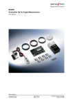
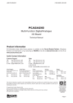
EKL01
Evaluation Kit for Length Measurement
User Manual
EKL01.DSE.03
www.sensitec.com
© Sensitec GmbH
User Manual
Page 1 of 12
Subject to technical changes
August 13th 2008
EKL01
Evaluation Kit for Length Measurement
User Manual
This evaluation kit provides the opportunity to learn the features and benefits of AMR sensor
technology, as used in angle measurement systems, in a quick and easy manner.
Please note, that the parts are sensitive to electrostatic fields.
Please take care to observe the polarity of the signal processing circuit and do not change
the jumper while a voltage is applied.
Please do not solder too hot resp. too long. That can damage the sensor.
Please do not touch parts with the magnet or other magnetic parts and keep it away from
strong electromagnetic fields.
The kit includes a 9 V battery and a cable including voltage controller and an LED for displaying the
output signal (green A, red B rectangular signal). If an external voltage supply is used (+ 5 V) this can
be connected directly to the signal processing circuit. In this case a connecting cable is not
necessary.
The products included in this package are not RoHS-compliant and are therefore not intended for
private use. Please follow local regulations regarding the disposal of batteries. Sensitec can dispose
of the parts on your behalf if they are returned cost-free to our premises.
www.sensitec.com
© Sensitec GmbH
User Manual
Page 2 of 12
Subject to technical changes
August 13th 2008
EKL01
Evaluation Kit for Length Measurement
The quality of the measurement signals and the subsequent evaluation depends primarily on the
measuring setup and the arrangement of the sensor and the measurement scale. Please keep this in
mind when first using the evaluation kit. A mechanical guidance mechanism, which guides the sensor
along the scale is ideal.
The components have been specially selected to allow study of the different influences on the
resolution and accuracy of a length measurement system, for example the pitch of the magnetic
scale or the interpolation factor of the interpolation ASIC.
The scales have a different colour depending on the pole pitch and can thus be assigned easily to
the corresponding sensors. With the exception of the LK40 sensor (yellow), which can be used for
pole pitches above 2 mm, all other sensors have a fixed assignment to a scale with a corresponding
pole pitch.
The standard measuring configuration between sensor and scale is shown in figure 5 of the
enclosed overview of measuring configurations.
Figures 1, 2, 3 and 4 show arrangements which can be executed using the LK40 sensor and
the bar magnet. Sensors of the LK14, LK16 and LK29 series are not suitable for this
arrangement.
A reference value for the maximum air gap between the leading face of the sensor and the scale
surface is half the pitch measured in mm. For further information and advice please do not hesitate to
contact us.
www.sensitec.com
© Sensitec GmbH
User Manual
Page 3 of 12
Subject to technical changes
August 13th 2008
EKL01
Evaluation Kit for Length Measurement
Setting up Measurements
Configuration
Application Example
1
Rotating magnet; sensor mounted in the
axis of rotation on a substrate.
Absolute angle measurement up to 180°
at the shaft end (axial).
2
Rotating magnet; sensor mounted on a
substrate perpendicularly to the axis of
rotation.
Absolute angle measurement up to 180°
at the shaft end (radial).
3
Magnet moves linearly; sensor mounted
at the edge of a substrate.
Absolute length measurement along a
magnet.
4
Magnet moves linearly; sensor mounted
at the edge of a substrate.
Magnetic switch.
Incremental length measurement.
5
Linear magnetic scale with fixed pole
length (pitch); sensor mounted perpendicularly to the magnetic track on the
scale.
No
Depiction
www.sensitec.com
© Sensitec GmbH
User Manual
Page 4 of 12
Subject to technical changes
August 13th 2008
EKL01
Evaluation Kit for Length Measurement
Testboard EA-nI-0060601
Signal with Interpolation ASIC
Characteristic
• Interpolation factor: 1, 10, 50
• Variable interpolation with jumper
• TTL/CMOS compatible output
• Output incremental
• Output frequency AX/BX up to 400KHz
Application
• Decoder incremental angle- and length resolution with a phase shift of 90°
• Resolution for incremental encoders
Short Description
The signal processing of the MR sensor signals is carried out by means of the interpolation ASIC. It
is based on amplifiers, A/D converters and logic circuits. By means of the amplifier the signals are
amplified in such a way that the A/D converter works in an optimized range. The amplified sensor
signals are led to the SIN and COS connections. These connections should not be used during
operation, because loading of the circuit could falsify the measurement signal. The sensor signal is
output as rectangular signals with a 90° phase shift and the appropriate resolution at the AX and BX
connections (green and red LED). When using the corresponding measurement scale the required
input signal for the interpolation ASIC is provided by the LK14, LK16, LK29 or LK40 AMR sensor.
The interpolation generates a multiple of the basic period of the system. An interpolation factor of 1 is
equivalent to a comparator and both sensor signals have a resolution of 4 flanks.
www.sensitec.com
© Sensitec GmbH
User Manual
Page 5 of 12
Subject to technical changes
August 13th 2008
EKL01
Evaluation Kit for Length Measurement
Technical Data
Power supply :
Current consumption:
Temperature range:
Input signal:
Output signal:
5 VDC ± 10 %
< 30 mA (output active)
-20 °C up to +70 °C
differential 100 mV ± 20 %
square wave phase shift 90°
Pin Assignment
No.
Name
Function
1
VDD1
+5 VDC power supply
2
GND1
Ground
3
AX
Incremental output track A
4
BX
Incremental output track B
5
SIN
Amplifier output SIN
6
COS
Amplifier output COS
7
GND1
Additional ground
8
VDD1
+5 VDC power supply for MR sensor
9
FC1
Cos 1 input for MR sensor
10
FC2
Cos 2 input for MR sensor
11
FS2
Sin 2 input for MR sensor
12
FS1
Sin 1 input for MR sensor
13
GND1
Ground for MR sensor
Pin Configuration EA-nI-0060601
www.sensitec.com
© Sensitec GmbH
User Manual
Page 6 of 12
Subject to technical changes
August 13th 2008
EKL01
Evaluation Kit for Length Measurement
LK14A AMR sensor for Length Measurement
The LK14A is a magnetoresistive FIXPITCH sensor, with an active structure adapted to a
measurement scale with a 5 mm pole pitch. The sensor chip features 2 complete Wheatstone
bridges. The signal at the output of the first bridge corresponds to the sine of the measurement
scale, while the matching cosine signal is available at the output of the second bridge. The sensor
operates without the need for a stabilising magnetic field. As long as the sensor is used in saturation,
the amplitude is largely independent of the air gap. Typically that is up to half the pitch of the
measurement scale (2.5 mm air gap). A separation of up to 3.5 mm is possible with reduced
performance.
Absolute Maximum Ratings
Maximum voltage
|UB|
Operating temperature range
≤ 5.5 V
T
-20 °C up to +85 °C
Electrical Characteristics (25 °C, H > 30 kA/m):
Sensor resistance
RS
(1.5 ± 0.5) kΩ
Bridge resistance
RB
(3 ± 1) kΩ
Ua/UB
≥ 9.5 mV/V
Signal amplitude in the operating distance
Offset
|Uoff/UB|
|∆Uoff / UB ∆t|
Offset drift
Temperature coefficient of signal amplitude
Temperature coefficient of Rs
≤ 1 mV/V
≤ 100 nV/Vh
TKU
(-4.0 ± 0.8)* 10-3 K-1
TKRS
(2.6 ± 0.6) *10-3 K-1
Sensitec reserves the right to modify technical specifications without
prior notice.
Pin Configuration LK14AG
-UB
+UB
-SIN
+COS
-COS
+SIN
Sensor
www.sensitec.com
© Sensitec GmbH
User Manual
Page 7 of 12
Subject to technical changes
August 13th 2008
EKL01
Evaluation Kit for Length Measurement
LK16A AMR sensor for length measurement
The LK16A is a magnetoresistive FIXPITCH sensor, with an active structure adapted to a
measurement scale with a 2 mm pole pitch. The sensor chip features 2 complete Wheatstone
bridges. The signal at the output of the first bridge corresponds to the sine of the measurement
scale, while the matching cosine signal is available at the output of the second bridge. The sensor
operates without the need for a stabilising magnetic field. As long as the sensor is used in saturation,
the amplitude is largely independent of the air gap. Typically that is up to half the pitch of the
measurement scale (1 mm air gap). A separation of up to 1.5 mm is possible with reduced
performance.
Absolute Maximum Ratings
Maximum voltage
|UB|
Operating temperature range
T
≤ 5.5 V
-20 °C up to +85 °C
Electrical Characteristics (25 °C, H > 30 kA/m):
Sensor resistance
RS
(1.7 ± 0.6) kΩ
Bridge resistance
RB
(3.4 ± 1.2) kΩ
Signal amplitude in the operating distance
Offset
Ua/UB
≥ 8 mV/V
|Uoff/UB|
≤ 2 mV/V
|∆Uoff / UB ∆t|
Offset drift
Temperature coefficient of signal amplitude
Temperature coefficient of Rs
≤ 100 nV/Vh
TKU
(-4.0 ± 0.8)* 10-3 K-1
TKRS
(2.5 ± 0.6) *10-3 K-1
Sensitec reserves the right to modify technical specifications
without prior notice.
Pin Configuration LK16AG
-SIN
-UB
-COS
+COS
+UB
+SIN
Sensor
www.sensitec.com
© Sensitec GmbH
User Manual
Page 8 of 12
Subject to technical changes
August 13th 2008
EKL01
Evaluation Kit for Length Measurement
LK29A AMR sensor for Length Measurement
The LK29A is a magnetoresistive FIXPITCH sensor, with an active structure adapted to a
measurement scale with a 1 mm pole pitch. The sensor chip features 2 complete Wheatstone
bridges. The signal at the output of the first bridge corresponds to the sine of the measurement
scale, while the matching cosine signal is available at the output of the second bridge. The sensor
operates without the need for a stabilising magnetic field. As long as the sensor is used in saturation,
the amplitude is largely independent of the air gap. Typically that is up to half the pitch of the
measurement scale (0.5 mm air gap). A separation of up to 0.7 mm is possible with reduced
performance.
Absolute Maximum Ratings
Maximum voltage
|UB|
Operating temperature range
T
≤ 5.5 V
-20 °C up to +85 °C
Electrical Characteristics (25 °C, H > 30 kA/m):
Sensor resistance
RS
(1.8 ± 0.6) kΩ
Bridge resistance
RB
(3.6 ± 1.2) kΩ
Signal amplitude in the operating distance
Offset
Ua/UB
≥ 8 mV/V
|Uoff/UB|
≤ 2 mV/V
|∆Uoff / UB ∆t|
Offset drift
Temperature coefficient of signal amplitude
Temperature coefficient of Rs
≤ 100 nV/Vh
TKU
(-3.8 ± 0.8)* 10-3 K-1
TKRS
(2.6 ± 0.6) *10-3 K-1
Sensitec reserves the right to modify technical specifications
without prior notice
Pin Configuration LK29AG
-SIN
-UB
-COS
+COS
+UB
+SIN
Sensor
www.sensitec.com
© Sensitec GmbH
User Manual
Page 9 of 12
Subject to technical changes
August 13th 2008
EKL01
Evaluation Kit for Length Measurement
LK40B AMR sensor for Length Measurement
The LK40B is a magnetoresistive FREEPITCH sensor not tied to a particular pole length. The sensor
detects 2 pole magnets and pole lengths of more than 2 mm. It features 2 complete Wheatstone
bridges. The signal at the output of the bridges corresponds to the sine and cosine. The sensor
operates without the need for a stabilising magnetic field. As long as the sensor is used in saturation,
the amplitude is largely independent of the air gap. Typically that is up to half the pitch of the
measurement scale as long as the pole structure is regular. With reduced performance even a bigger
air gap is possible.
Absolute Maximum Ratings
Maximum voltage
|UB|
Operating temperature range
≤ 5.5 V
T
-40 °C up to +120 °C
@ 120 °C
limited lifetime 7200 h
Electrical Characteristics (25 °C, H > 30 kA/m):
Sensor resistance
RS
(1.7 ± 0.7) kΩ
Bridge resistance
RB
(3.4 ± 1.4) kΩ
Signal amplitude in the operating distance
Ua/UB
|Uoff/UB|
Offset
Offset drift
|∆Uoff / UB ∆t|
Temperature coefficient of signal amplitude
Temperature coefficient of Rs
8 - 13 mV/V
≤ 2 mV/V
≤ 100 nV/Vh
TKU
(-4.0 ± 0.8)* 10-3 K-1
TKRS
(2.6 ± 0.6) *10-3 K-1
Sensitec reserves the right to modify technical specifications
without prior notice.
Pin Configuration LK40BG
COS
UB
SIN
COS
UB
SIN
Sensor
www.sensitec.com
© Sensitec GmbH
User Manual
Page 10 of 12
Subject to technical changes
August 13th 2008
EKL01
Evaluation Kit for Length Measurement
Mechanical Dimensions of Ceramic Board
The thickness of the ceramic is 0.7 mm. The pads are covered with solderable material.
Kit content
Quantity
Article
Label
Note
3
LK14AG
White
1 unit incl. 200 mm cable for pole length 5 mm
3
LK16AG
Red
1 unit incl. 200 mm cable for pole length 2 mm
3
LK29AG
Black
1 unit incl. 200 mm cable for pole length 1 mm
3
LK40BG
Yellow
1 unit incl. 200 cable for pole length 2 mm and longer
1
MLI-1000-100
Blue
Linear scale 100 x 10 x 1.3 mm³ with 1 mm pole division
1
MLI-2000-100
Red
Linear scale 100 x 10 x 1.3 mm³ with 2 mm pole division
1
MLI-3000-100
White
Linear scale 100 x 10 x 1.3 mm³ with 5 mm pole division
1
EA-nl-0060601
Testboard incl. 3 interpolation factors
1
Cable
Battery cable with LED and connector
1
Battery
9 V battery
1
Magnet
Magnet 12 x 3 x 2 mm
1
Documentation
Pin configuration manual and data sheets
1
Package
ESD-package
www.sensitec.com
© Sensitec GmbH
User Manual
Page 11 of 12
Subject to technical changes
August 13th 2008
EKL01
Evaluation Kit for Length Measurement
General Information
Product Status
The product is in series production. Note: The status of the product may have changed since this user
manual was published. The latest information is available on the internet at www.sensitec.com.
Right to make changes
Sensitec GmbH reserves the
right to make changes, without
notice, in the products, including software, described or contained herein in order to improve design and/or performance. Sensitec GmbH assumes
no responsibility or liability for
the use of any of these products.
Application information
Applications that are described
herein for any of these products
are for illustrative purposes
only. Sensitec GmbH makes
no representation or warranty
that such applications will be
suitable for the specified use
without further testing or modification.
Life critical applications
These products are not qualified for use in life support appliances, aeronautical applications or devices or systems
where malfunction of these
products can reasonably be
expected to result in personal
injury.
Sensitec GmbH
Georg-Ohm-Straße 11
35633 Lahnau
Germany
Solutions for measuring:
• Position
• Angle
• Magnetic field
• Current
Fon +49 (0) 64 41/ 97 88-0
Fax +49 (0) 64 41/ 97 88-17
E-Mail [email protected]
www.sensitec.com
Copyright © 2008 by Sensitec GmbH, Germany
All rights reserved. No part of this document may be copied or reproduced in any form or by any means without
the prior written agreement of the copyright owner. The information in this document is subject to change without
notice. Sensitec GmbH does not assume any liability for any consequence of its use.
www.sensitec.com
© Sensitec GmbH
User Manual
Page 12 of 12
Subject to technical changes
August 13th 2008