1
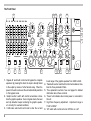
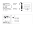
1. Balanced input XLR-3. The input impedance is 20K Ohm
balanced or 10K unbalanced. Each input leg has the same
impedance to ground to maximise input common mode rejection ratio, independent of source impedance. The maximum overload level of the input circuitry is +21dBu. Pin 1 of
the input connector is connected to chassis ground. Pin 2 is
the non-inverting (positive,) pin 3 the inverting (negative) input,
conform international standards.
2. Balanced output XLR -3. The output impedance is 100 Ohm
balanced or 50 Ohm unbalanced. The output can drive +21dBu
into 600 Ohm with low distortion. Pin 1 is connected to chassis
ground. Pin 2 is the non-inverting (positive,) pin 3 the inverting
(negative) input, conform international standards.
3. Mains inlet and fuseholder. The mains connector is a standard 3 pin IEC connector. The centre terminal is directly connected to the chassis of the unit and must be connected to the
earth terminal of the mains outlet. This is important for your
safety. The mains cable supplied with this unit is a universal
European model. Use only the polarised mains plug option
together with a polarised receptacle. This unit is equipped
with a single pole disconnect device (fuse) in the phase wire.
If an unpolarised mains connection is used the receptacle
the unit is connected to must be equipped with a two pole
disconnect device (fuse) of appropriate rating. In case the
mains plug on the mains cable is not conform to your local
standard, you will need to replace it with a suitable one. In this
case it is very important to respect the colour coding of the
wires:
The mains fuse is a standard 5x20mm fuse. Rating is indicated on the type label on the back of the unit. The fuse
drawer can easily be opened with a flat tip screwdriver. For
safety reasons, the mains cable must be removed before the
drawer can be opened. Replace only with the same fuse type
and rating. The auto-ranging power supply of the GE series
guarantees trouble free operation all over the world, independent of local mains conditions. Acceptable mains voltages
are in the range from 85 to 264 Vrms 50/60Hz. When mains
power is removed, the unit automatically
switches to
the bypass mode, hardware linking the input to the output by
means of the fail-safe relay.
4. The screws on both sides of the mains inlet are essential for
the safety of the unit. These screws connect the earth pin of
the mains connector to the chassis. These screws must be
well tightened at all times.
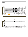
5. 15 pin SubD system connector. This connector integrates the
PE137 in the optional Q4audio equaliser drawer. The system
connector can also be used to monitor and control the unit
remotely in installations. See next page for layout and pinning
of the system connector.
yellow/green : earth ground
brown or black : phase (live)
blue : neutral
11