1
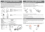
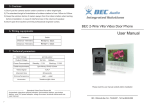
b.Alert user manual C.1102.11016B 10/9/2011 Kassandra NV Vincent Spruytte 1. CONTENT 1. content ............................................................................................................................................................ 2 2. parts ................................................................................................................................................................ 4 3. positioning remote sensors............................................................................................................................. 5 3.1. single semi-trailer .................................................................................................................................. 5 3.2. dual trailer ............................................................................................................................................. 6 3.3. what to avoid ......................................................................................................................................... 6 3.4. problem solving ..................................................................................................................................... 7 4. front panel....................................................................................................................................................... 8 5. setup USB stick ................................................................................................................................................ 9 6. startup unit ................................................................................................................................................... 10 7. 8. 9. 6.1. procedure ............................................................................................................................................ 10 6.2. Error coding ......................................................................................................................................... 10 6.2.1. no setup data .................................................................................................................................. 10 6.2.2. no connection with the cabin sensor .............................................................................................. 10 6.2.3. interface not working ...................................................................................................................... 10 menu structure ............................................................................................................................................. 11 7.1. principle ............................................................................................................................................... 11 7.2. main menu........................................................................................................................................... 11 7.3. the sensors .......................................................................................................................................... 11 7.4. the gsm modem ................................................................................................................................... 12 7.5. the batteries ........................................................................................................................................ 12 7.6. random fun .......................................................................................................................................... 13 alarm ............................................................................................................................................................. 14 8.1. phase 1 ................................................................................................................................................ 14 8.2. phase 2 ................................................................................................................................................ 14 8.3. reset alarm........................................................................................................................................... 14 de-activate .................................................................................................................................................... 15 user manual 2/20 10. drive ......................................................................................................................................................... 16 11. charge remote units ................................................................................................................................. 17 12. upgrade software ..................................................................................................................................... 18 13. problem solving........................................................................................................................................ 19 14. figures and tables ..................................................................................................................................... 20 user manual 3/20 2. PARTS Figure 1 package The package contains - The main unit (MU) to install in the cabin o 1 mobile phone antenna o 1 WIFI antenna o 1 cable to connect to different alarm outputs - 1 cabin sensor - 2 remote sensors - 1 power charge cable for both remote sensors and for main unit - 1 connector to connect the unit to a permanent power line - 1 USB stick with the setup user manual 4/20 3. POSITIONING REMOTE SENSORS 3.1. SINGLE SEMI-TRAILER Figure 2 position of sensor at the back The sensors have to be positioned on the chassis of the trailer. One sensor as far as possible to the back, one sensor as far as possible to the front. One sensor to the left, one to the right. It does not matter if the front is left and the back right or vice versa. One should avoid that the back sensor is behind a metal structure as shown on Figure 2 and Figure 3. The sensors need to be connected with their magnets horizontally (bottom) and vertically, i.e. on the side to avoid losing them during driving. user manual 5/20 Figure 3 position of sensor at the front 3.2. DUAL TRAILER The sensors have to be positioned on the chassis of the trailer. One sensor in the middle of the first part, one in the middle of the second part. One sensor to the left, one to the right. It does not matter if the front is left en the back right or vice versa. One should avoid that the back sensor is behind a metal structure as shown on $. The sensors need to be connected with their magnets horizontally (bottom) and vertically, i.e. on the side to avoid losing them during driving. 3.3. WHAT TO AVOID • Positioning of sensors behind a metal box • Positioning of sensors at another angle than perpendicular to the long side of the trailer user manual 6/20 3.4. PROBLEM SOLVING • In the menu structure of 7.3 it is possible to see the connection quality of the sensors • When there is no contact with the sensors or one of both sensors o Put them in the cabin. The LED should light up. If no, the battery is too low o If the LED light up, go to the trailer and position the sensors o The LED’s should stay on, if not, the position of the sensor is shielded and one should find another position By changing left/right By putting the sensor a bit more to the front or to the back user manual 7/20 4. FRONT PANEL The front panel has 4 elements, as can be seen on Figure 4. • On the left: start/stop button • On the right • o 4 indicator LED’s o 4 control buttons In the middle : USB connector user manual 8/20 5. SETUP USB STICK The USB stick contains the setup information concerning the working of the system and the procedure to give an alarm. Every alarm is given in 2 steps and it is possible to choose how this is given. This information is on the usb stick. Before starting the system, the usb stick needs to be placed in its position in the front of the MU. Figure 4 front panel MU without USB Figure 5 front panel with USB user manual 9/20 6. STARTUP UNIT 6.1. 6.2. PROCEDURE • Push shortly the left button. The blue LED will go on • It takes 3 minutes to start the system and to warm up. During this time, no further indication is given. • LED 3 start working • LED’s 1 to 4 will start consecutively • The LED’s start indicating following the normal working of the system (see further) ERROR CODING 6.2.1. NO SETUP DATA When there is no usb stick or the setup files are missing, the system is not able to start. A error will be given by the LED’s 1 and 4 who will be blinking. 6.2.2. NO CONNECTION WITH THE CABIN SENSOR When the cabin sensor is not connected or there is something wrong with the cabling, the LED’s 2 an error will be given by the LED’s 2 and 3 who will be blinking. 6.2.3. INTERFACE NOT WORKING If the human interface 1 is not working, the system will shutdown automatically. 1 Modem, LED’s, buttons, … user manual 10/20 7. MENU STRUCTURE 7.1. PRINCIPLE There are 5 menu levels • Main menu • Details about the sensors • Details about the GSM modem • Details about the batteries of the remote units • Random LED’s With button 2 it is possible to walk through these menu levels. Every time one pushes this button the menu goes one step further. To be able to know which menu is active, the last menu, the random up lighting LED’s is created as a reference. The next menu is again the main menu. 7.2. MAIN MENU Table 1 main menu LED 1 Sensors and system activated LED 2 Mobile phone activated and online LED 3 Battery level 1 LED 4 Battery level 2 The battery levels give an indication of the battery level of the RU with the lowest battery level. When 2 LED’s (3 and 4) are up, they are at maximum load. When both LED’s are out, it is time to charge the RU. 7.3. THE SENSORS user manual 11/20 Table 2 sensor menu LED 1 System activated LED 2 Cabin sensor activated LED 3 Remote unit 1 activated LED 4 Remote unit 2 activated 7.4. THE GSM MODEM Table 3 the modem LED 1 GSM modem present LED 2 SIM card present and pin code ok LED 3 GSM modem active LED 4 GSM modem online 7.5. THE BATTERIES Table 4 main menu LED 1 Level 1 LED 2 Level 2 LED 3 Level 3 LED 4 Level 4 The battery levels give an indication of the battery level of the RU with the lowest battery level. When 4 LED’s are up, they are at maximum load. When only LED 1 is on, it is time to charge the RU. user manual 12/20 7.6. RANDOM FUN Reference menu. LED’s will go on and off in a random way. user manual 13/20 8. ALARM The alarm is given in 2 phases. With the setup program and the USB stick, it is possible to define what happens at what level: 8.1. • Buzzer in cabin • Message on mobile phone • 3 digital outputs to connect to o Board computer o Horn o Lights o … PHASE 1 It is best to use this as a mild alarm and to activate some actions that could scare of a real intruder and do not disturb anybody further when the intrusion was caused by a accidental situation like a foot ball shot to the side of the trailer. 8.2. PHASE 2 With this phase, a real intrusion is detected. The maximum of actions should be taken. On the unit, the four LED’s are blinking. 8.3. RESET ALARM The alarm can be reset by pushing button 1. The system goes back to the main menu. user manual 14/20 9. DE-ACTIVATE When the truck is loaded or unloaded, or when the driver needs to open the trailer, for instance for inspection by the custom services, an alarm should not be given. By pushing button 4, the system is deactivated and will not give an alarm. The LED’s 1 and 4 are blinking. By pushing button 4 again, the system is re-activated. When the truck drives of, without re-activation, the system will be re-activated after the truck has stopped again. user manual 15/20 10. DRIVE When the truck drives, this is detected automatically and the system is de-activated. The moment the truck is stopped, the system starts again. user manual 16/20 11. CHARGE REMOTE UNITS The remote units can be charged with the cable delivered with the system. It can be connected to any power between 6V and 30V. A full charge takes ca 4.5 hours. user manual 17/20 12. UPGRADE SOFTWARE When necessary, it is possible to put a software upgrade on the USB sick (see manual software). When the system is started and it finds the upgrade file, the upgrade is performed automatically and the system is restarted. user manual 18/20 13. PROBLEM SOLVING user manual 19/20 14. FIGURES AND TABLES Figure 1 package .................................................................................................................................................... 4 Figure 2 position of sensor at the back .................................................................................................................. 5 Figure 3 position of sensor at the front ................................................................................................................. 6 Figure 4 front panel MU without USB .................................................................................................................... 9 Figure 5 front panel with USB ................................................................................................................................ 9 Table 1 main menu............................................................................................................................................... 11 Table 2 sensor menu ............................................................................................................................................ 12 Table 3 the modem .............................................................................................................................................. 12 Table 4 main menu............................................................................................................................................... 12 user manual 20/20