1
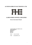
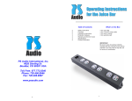
User Manual PowerPlay IPC-8000 and IPC-9000 4826 Sterling Drive, Boulder CO 80301 PH: 720.406.8946 [email protected] www.psaudio.com ©2010 PS Audio International Inc. All rights reserved. 15-052-01-1-DOM-B Safety Information PowerPlay IPC-8000 and IPC-9000 Safety Information Important Safety Information 1) Read these instructions. 2) Keep these instructions. 3) Heed all warnings. 4) Follow all instructions. 5) Do not use this apparatus near water. 6) Clean only with dry cloth. 7) Do not block any ventilation openings. Install in accordance with the manufacturer’s instructions. 8) Do not install near any heat sources such as radiators, heat registers, stoves, or other apparatus (including amplifiers) that produce heat. 9) Do not defeat the safety purpose of the polarized or grounding-type plug. A polarized plug has two blades with one wider than the other. A grounding type plug has two blades and a third grounding prong. The wide blade or the third prong are provided for your safety. If the provided plug does not fit into your outlet, consult an electrician for replacement of the obsolete outlet. 10) Protect the power cord from being walked on or pinched particularly at plugs, convenience receptacles, and the point where they exit from the apparatus. 11) Only use attachments/accessories specified by the manufacturer. 12) Use only with the mounting brackets specified by the manufacturer, or sold with the apparatus. 14) Refer all servicing to qualified service personnel. Servicing is required when the apparatus has been damaged in any way, such as when the power supply cord or plug is damaged, liquid has been spilled or objects have fallen into the apparatus, the apparatus has been exposed to rain or moisture, does not operate normally, or has been dropped. 4826 Sterling Drive, Boulder CO 80301 PH: 720.406.8946 [email protected] www.psaudio.com ©2010 PS Audio International Inc. All rights reserved. 15-052-01-1-DOM-B Table of Contents PowerPlay IPC-8000 and IPC-9000 Table of Contents Safety Information.........................................................................................................................................2 Introduction ..................................................................................................................................................4 Device Description ................................................................................................................................................... 4 Device Features........................................................................................................................................................ 4 Installation ....................................................................................................................................................6 Unpacking and Inspection ........................................................................................................................................ 6 Overview ................................................................................................................................................................. 7 Self Test and Power Up .......................................................................................................................................... 10 IP Status................................................................................................................................................................. 11 Configuration and Use .................................................................................................................................12 Web Based Configuration....................................................................................................................................... 12 Account Login.............................................................................................................................................................. 13 User Controls .............................................................................................................................................................. 14 My Device List ............................................................................................................................................................. 15 Control ........................................................................................................................................................................ 16 Configure..................................................................................................................................................................... 17 IR Control .................................................................................................................................................................... 22 Email Alerts ................................................................................................................................................................. 23 Performance................................................................................................................................................................ 24 Wattage....................................................................................................................................................................... 25 Temperature ............................................................................................................................................................... 26 Network ...................................................................................................................................................................... 27 Scheduling ................................................................................................................................................................... 28 Internal Website .................................................................................................................................................... 29 System Status.............................................................................................................................................................. 29 Configuration .............................................................................................................................................................. 30 Network ...................................................................................................................................................................... 34 Front Panel Control and Configuration ................................................................................................................... 35 IPC-‐9000 ...................................................................................................................................................................... 35 IPC-‐8000 ...................................................................................................................................................................... 38 Firmware Updates .......................................................................................................................................39 Remote Firmware Updates..................................................................................................................................... 39 Local Firmware Update .......................................................................................................................................... 41 Warranty .....................................................................................................................................................42 Specifications ..............................................................................................................................................47 4826 Sterling Drive, Boulder CO 80301 PH: 720.406.8946 [email protected] www.psaudio.com ©2010 PS Audio International Inc. All rights reserved. 15-052-01-1-DOM-B Table of Contents PowerPlay IPC-8000 and IPC-9000 Introduction Device Description PowerPlay is a revolutionary power conditioner, which not only offers world class protection and noise reduction, but also offers unparalleled flexibility and control from anywhere in the world. Device Features • Advanced Control Ethernet and RS-232 ports provide two way communication to the PowerPlay. These ports enable unparalleled control, monitoring, and management of connected devices. • Simple Control Infrared, 12 volt trigger and Phone communications port provide several additional methods controlling the PowerPlay and connected devices. • Intelligent UPS Control The UPS communication port enables PS Audio’s revolutionary Intelligent UPS Management control and configuration. Additionally information is also provided via the front panel of PowerPlay and the PS Audio Global Net site when a PowerPack UPS is connected. • Power Monitoring The PowerPlay monitors and reports detailed power conditions whenever the unit is connected to PS Audio Global Net. • Noise Reduction The PowerPlay contains powerful noise filtration, yet continues to deliver unimpeded current to your components for optimal performance. • Surge Protection Sophisticated surge and spike protection is contained in the PowerPlay. The protection circuitry is designed to protect your gear from voltage irregularities. Should the protection circuitry become compromised the PowerPlay will no longer supply power to any of the connected components. • IsoZonesTM The PowerPlay IPC-9000 features 5 IsoZonesTM, while the IPC-8000 features 3. Each IsoZoneTM employs differential mode filtering to isolate connected equipment from noise which is generated by other components. It is recommended that components be isolated by device type 4826 Sterling Drive, Boulder CO 80301 PH: 720.406.8946 [email protected] www.psaudio.com ©2010 PS Audio International Inc. All rights reserved. 15-052-01-1-DOM-B Introduction PowerPlay IPC-8000 and IPC-9000 (digital, analog, video, etc.) and/or by power supply type (switch mode or linear) wherever possible. The PowerPlay IPC-8000 features 2 IsoZonesTM. • Rack Mountable The PowerPlay IPC-8000 and IPC-9000 are rack mountable using the included rack mounting hardware. • Removable Support Feet The feet of the PowerPlay may be removed in order to save rack space. • ON/OFF Sequencing • Outlet ON/OFF Bank Control • Auto Reboot When enabled the Auto Reboot feature will reboot your modem, router, and/or any other device critical for internet access when PowerPlay is unable to connect to the web for more than 10 minutes. This feature helps to ensure your PowerPlay is always available online. 4826 Sterling Drive, Boulder CO 80301 PH: 720.406.8946 [email protected] www.psaudio.com ©2010 PS Audio International Inc. All rights reserved. 15-052-01-1-DOM-B Installation PowerPlay IPC-8000 and IPC-9000 Installation Unpacking and Inspection Upon receipt inspect the packaging for damage. Remove PowerPlay from the box and inventory the package contents listed below. Immediately report any damage or missing components to the shipping agent and/or your dealer. Package Contents Item 1 2 3 4 5 6 7 8 9 Item Description PowerPlay IPC-9000 or 8000 Quick Start User Guide AC Input Power Cord Coaxial Patch Cables Telephone Patch Cable Ethernet Patch Cable Equipment Protection Policy Sheet SD Card Rack Mount Kit 4826 Sterling Drive, Boulder CO 80301 PH: 720.406.8946 [email protected] www.psaudio.com ©2010 PS Audio International Inc. All rights reserved. Quantity 1 ea. 1 ea. 1 ea. 2 ea. 1 ea. 1 ea. 1 ea. 1 ea. 1 ea. 15-052-01-1-DOM-B Installation PowerPlay IPC-8000 and IPC-9000 Overview IPC-9000 Rear Panel 4826 Sterling Drive, Boulder CO 80301 PH: 720.406.8946 [email protected] www.psaudio.com ©2010 PS Audio International Inc. All rights reserved. 15-052-01-1-DOM-B Installation PowerPlay IPC-8000 and IPC-9000 IPC-8000 Rear Panel 4826 Sterling Drive, Boulder CO 80301 PH: 720.406.8946 [email protected] www.psaudio.com ©2010 PS Audio International Inc. All rights reserved. 15-052-01-1-DOM-B Installation PowerPlay IPC-8000 and IPC-9000 Installation Placement PowerPlay must be installed in a protected environment away from heat emitting devices. Do not install this unit where it may be exposed to excessive moisture. Rack Mounting Rack mounting hardware is provided for use with your PowerPlay. Please us only the included hardware for rack mounting the device. Remove and retain the 3 #8 screws located on each side of the PowerPlay, nearest to the front faceplate. Use the same 3 #8 screws removed from the chassis to attach each of the rack mounting ears to the side of the unit. Finally use the 4 pan-head screws to mount the unit in the rack. Ventilation Ensure adequate airflow around the device. Do not block any ventilation holes. SD Card Installation Remove the SD card from the accessory package and insert into the SD card slot on the rear panel. In order to perform remote firmware updates the SD card MUST be installed in the SD card slot and remain unlocked. Connect to AC The voltage specifications for the PowerPlay can be found on the back panel of the unit. Prior to plugging the unit into the AC power ensure the voltage and frequency of the device match the power provided by the wall Plug the PowerPlay into a 2 pole, 3 wire grounded receptacle (wall outlet).* *When used with the optional PowerPack UPS-1500 plug the PowerPlay into the PowerPack using the included IEC male to IEC female cable and the UPS control patch cord. Determining the Load If rated capabilities are exceeded an overload condition may occur and cause the device to shut down and/or trip the circuit breaker. In order to determine the load follow these steps: 1. Make a list of all devices you will power from the PowerPlay and the power consumption ratings of each. This information can generally be found on each device near the AC inlet or in the device’s operations manual. 2. Calculate the sum of the consumption ratings. 3. Ensure that the total consumption does not exceed the capabilities of the PowerPlay. If the load exceeds rated capabilities we suggest using an additional PowerPlay device in order to protect and control your equipment. 4826 Sterling Drive, Boulder CO 80301 PH: 720.406.8946 [email protected] www.psaudio.com ©2010 PS Audio International Inc. All rights reserved. 15-052-01-1-DOM-B Installation PowerPlay IPC-8000 and IPC-9000 Connect the Load Connect each of the devices to be powered by the PowerPlay. Be sure to make a list of each device and the power zone in which they are located. Connect Phone To protect any device which connects to the telephone line connect the telephone cable from the wall outlet to the “TELEPHONE IN” jack on the PowerPlay. Then connect the telephone cable to the “TELEPHONE OUT” jack on the PowerPlay and to the device. To use the Phone Control features of the IPC-9000 connect a dedicated phone line or extension using a standard telephone cable into the “PHONE” jack. Connect Satellite / Cable / Antenna To protect satellite, cable, and/or antenna devices connect the coaxial cable from the wall to the coaxial “IN” jack on the PowerPlay. Then connect the coaxial cable to the “OUT” jack of the vertically grouped input and output pair on the PowerPlay and then to the device. Connect to the Internet To protect any device which connects to the internet connect the Ethernet cable from the wall outlet to the “DATA IN” jack on the PowerPlay. Then connect the Ethernet cable to the “DATA OUT” jack on the PowerPlay and to the device. To enable web based control, connect an Ethernet cable from a live connection to the “ETHERNET” jack on the PowerPlay. Self Test and Power Up When the PowerPlay is plugged into the wall or when it recovers from a power failure it will run a short self test. During the self test the device will illuminate the display window and display model and firmware information Upon completion of the self test, PowerPlay may be turned on by pressing the PS Audio blue logo button in the center of the front panel. 4826 Sterling Drive, Boulder CO 80301 PH: 720.406.8946 [email protected] www.psaudio.com ©2010 PS Audio International Inc. All rights reserved. 15-052-01-1-DOM-B Installation PowerPlay IPC-8000 and IPC-9000 IP Status Once connected to the internet the PowerPlay’s proprietary internet connection service will auto detect and configure the required settings. An IP status indicator light is provided on the front panel to indicate the status as follows: Red – PowerPlay is not connected to the local network. Check to make sure the Ethernet cable is connected between PowerPlay and an active network connection. Yellow – PowerPlay is connected to the local network, but not to the web. Green – PowerPlay is connected to the local network and the web. Configuration and control can now be performed either through the external or internal websites. By default PowerPlay is setup to rely on a DHCP enabled router or switch. If you are unable, or do not wish, to enable DHCP on the router or switch please refer to section titled 2.6.2 Internal Website Configuration to configure the PowerPlay as a static device within the local network. 4826 Sterling Drive, Boulder CO 80301 PH: 720.406.8946 [email protected] www.psaudio.com ©2010 PS Audio International Inc. All rights reserved. 15-052-01-1-DOM-B Configuration and Use PowerPlay IPC-8000 and IPC-9000 Configuration and Use There are 3 methods for configuring and controlling the PowerPlay. The preferred and most powerful method is via the PS Audio hosted site http://powerplay.psaudio.com. When the internet is unavailable or if the network requires advanced setup the internal website is the next best method. The final and most limited method of control configuration is accomplished via the front panel. Web Based Configuration The external website http://powerplay.psaudio.com is the preferred method for configuring and controlling the PowerPlay. However this method requires the PowerPlay to have access to the World Wide Web, and a green IP indicator on the front panel. In order to register you will need to create an account with PS Audio and you will need to know the unit ID number of the unit or units you would like to register. The unit ID number can be obtained from the rear panel of the device or by one of the following methods: IPC-9000 - touch the IP indicator repeatedly until the display window shows: “UNIT ID” “######” IPC-8000 - press the status button repeatedly until the display window shows: “UNIT ID” “######” 4826 Sterling Drive, Boulder CO 80301 PH: 720.406.8946 [email protected] www.psaudio.com ©2010 PS Audio International Inc. All rights reserved. 15-052-01-1-DOM-B Configuration and Use PowerPlay IPC-8000 and IPC-9000 Account Login With the unit ID number in hand visit http://powerplay.psaudio.com. If you have not created an account already you will need to do so at this time using the ‘Register’ link. Note: If you are a PS Audio Dealer be sure to select ‘Dealer’ under User Type during the registration process. This will unlock additional levels of control for others within your organization. Upon first login dealers must setup a minimum of one Installer account prior to setting up an end user, or customer, account. 4826 Sterling Drive, Boulder CO 80301 PH: 720.406.8946 [email protected] www.psaudio.com ©2010 PS Audio International Inc. All rights reserved. 15-052-01-1-DOM-B Configuration and Use PowerPlay IPC-8000 and IPC-9000 User Controls Upon login, GlobalNet will present the ‘User Control’ page. For end users this page will list all of the devices registered to their account. As illustrated below: Dealer and Installer accounts will first see their Dealer or Installer controller panel. This form of the control panel will allow for the quick selection of User or Customer accounts for configuration and control. From here new users may be added by selecting ‘Add User’. It is suggested that this be completed with the information of the end user. 4826 Sterling Drive, Boulder CO 80301 PH: 720.406.8946 [email protected] www.psaudio.com ©2010 PS Audio International Inc. All rights reserved. 15-052-01-1-DOM-B Configuration and Use PowerPlay IPC-8000 and IPC-9000 In order to view the devices registered to a customer or user, simply click on their name. After clicking on a customer name Globalnet will present the ‘User Control’ the same as it would if logged in from the customer account. My Device List – Click here to see a full list of the devices registered to you. Register Device – Click here to register a new PowerPlay device. User Information – Click here to edit your account information, including password and email. Logout – Click here to sign off of the PowerPlay site. My Device List From the My Device List you can identify and select any PowerPlay registered to your account. To control one of your PowerPlays click on the corresponding COMMAND CENTER button. Note: When a PowerPlay is offline the ‘COMMAND CENTER’ button will be grey instead of blue. Although two way communication is not possible you may alter the settings of the device. When the offline unit reconnects all web based changes will override the settings on the box. 4826 Sterling Drive, Boulder CO 80301 PH: 720.406.8946 [email protected] www.psaudio.com ©2010 PS Audio International Inc. All rights reserved. 15-052-01-1-DOM-B Configuration and Use PowerPlay IPC-8000 and IPC-9000 Control Once you have identified and selected the PowerPlay you would like to control you will be taken to the Command Center – Control Tab. From the Device Command Center you can control the Master Power or reboot any outlet with the click of a button, or use the tabs to drill down for more advanced control. 4826 Sterling Drive, Boulder CO 80301 PH: 720.406.8946 [email protected] www.psaudio.com ©2010 PS Audio International Inc. All rights reserved. 15-052-01-1-DOM-B Configuration and Use PowerPlay IPC-8000 and IPC-9000 Configure The Configure tab is the most powerful page for your PowerPlay. From this page you can label the devices connected to your PowerPlay, toggle the power for any outlet, set the switch mode for each device, set the priority for battery backup, lock the front panel, dim the display, and alter the output trigger delay. Outlet Labeling You may label each outlet to match the device connected. Type the desired label in the text field above each outlet. 4826 Sterling Drive, Boulder CO 80301 PH: 720.406.8946 [email protected] www.psaudio.com ©2010 PS Audio International Inc. All rights reserved. 15-052-01-1-DOM-B Configuration and Use PowerPlay IPC-8000 and IPC-9000 Power Toggle By clicking on the Power Switch you may turn the power to the outlet on or off. Switch Mode You may change the way each outlet interacts with the Master Power button by altering the switch mode as follows: Switched The outlet will follow the state of the Power Button Delay The outlet will follow the state of the Power Button after a 3 second delay Program Delay The outlet will follow the state of the Power Button after a programmed delay. Note: The Program Delay can only be altered through the web based interfaces, the default is 3 seconds. 4826 Sterling Drive, Boulder CO 80301 PH: 720.406.8946 [email protected] www.psaudio.com ©2010 PS Audio International Inc. All rights reserved. 15-052-01-1-DOM-B Configuration and Use PowerPlay IPC-8000 and IPC-9000 Reboot The outlet is ALWAYS ON, but may be rebooted through the web interface Auto Reboot The outlet is ALWAYS ON, may be rebooted from the web interface, and automatically reboots when no web connection is detected for 10 continuous minutes. When Auto Reboot is selected you may use the delay setting to sequence power of all Auto Reboot outlets. For example you may set your modem and router to reboot with a 30 second delay between the two by setting the modem delays to 3 seconds and the router delay to 33 seconds. Always On The outlet remains on regardless of the state of the Power Button UPS Priority When PowerPlay is connected to a PS Audio PowerPack battery backup you may control how each outlet shuts down in a battery backup situation. Using the drop box you may select one of the following options: None – No battery backup is provided to these outlets in order to quickly reduce the load and extend battery life. Use this setting for amps, subwoofers and other large draw devices. Normal – Some battery protection is provided, but outlets turn off when UPS reaches 25% battery remaining. Use this setting to safely shut down devices such as projectors or any other device which require some user interaction to properly shut down 4826 Sterling Drive, Boulder CO 80301 PH: 720.406.8946 [email protected] www.psaudio.com ©2010 PS Audio International Inc. All rights reserved. 15-052-01-1-DOM-B Configuration and Use PowerPlay IPC-8000 and IPC-9000 Critical – Full battery protection. Outlets remain powered until battery runs out. Use this setting for network critical or other devices which need to remain powered as long as possible. Important: All battery backup devices, including the PowerPack, are limited in load capabilities. Reducing the load quickly will greatly extend the battery backup time. Front Panel Controls You may Lock the front panel of the PowerPlay device, thus disabling any local control via the front panel. To lock the front panel select ‘Locked’ from the front panel controls drop menu. Note: The main power button will continue to function and control the main power state of the device. Unit Display Brightness The display on the PowerPlay device offers three settings, Bright, Dim and Off. The dropbox allows the configuration of this feature remotely. 4826 Sterling Drive, Boulder CO 80301 PH: 720.406.8946 [email protected] www.psaudio.com ©2010 PS Audio International Inc. All rights reserved. 15-052-01-1-DOM-B Configuration and Use PowerPlay IPC-8000 and IPC-9000 Phone Password The PowerPlay 9000 may be connected directly to a phone line to allow for voice guided control via phone. This feature requires a dedicated line or extension be connected to the Phone input on the rear of the PowerPlay. The default password for accessing the phone control is “1234”. To alter the password simply enter the new password here. Important: Changes made in the configuration tab must be confirmed by clicking on the ‘SUBMIT CHANGES’ button at the top of the page. 4826 Sterling Drive, Boulder CO 80301 PH: 720.406.8946 [email protected] www.psaudio.com ©2010 PS Audio International Inc. All rights reserved. 15-052-01-1-DOM-B Configuration and Use PowerPlay IPC-8000 and IPC-9000 IR Control The IR Control tab allows you to setup your PowerPlay to issue IR commands to any connected device as if you were standing there with the original remote for the device. In order for this feature to work, you must integrate your PowerPlay with an IR distribution system. IR commands follow the power state of the PowerPlay device, with the exception of the Unlinked Commands. To add a command slect the ‘ADD’ button. IR commands may be selected from the drop down menu, or entered by pasting hex code. Click ‘Save’ when finished. 4826 Sterling Drive, Boulder CO 80301 PH: 720.406.8946 [email protected] www.psaudio.com ©2010 PS Audio International Inc. All rights reserved. 15-052-01-1-DOM-B Configuration and Use PowerPlay IPC-8000 and IPC-9000 Email Alerts One of the most distinguishing features of PowerPlay is its ability to alert you to possible problems with your system. The Email Alerts tab will allow you to configure email alerts. Configuring your emails alerts is easy, just check the boxes next to the alerts you wish to receive, enter the email address or addresses you wish them to be sent to and click ‘SAVE CHANGES’. Tip: PowerPlay can send the alerts directly to your cell phone! Most phones can receive text based alerts via email. Contact your cell service provider to determine the address which can be entered here to provide reports to your cell phone. 4826 Sterling Drive, Boulder CO 80301 PH: 720.406.8946 [email protected] www.psaudio.com ©2010 PS Audio International Inc. All rights reserved. 15-052-01-1-DOM-B Configuration and Use PowerPlay IPC-8000 and IPC-9000 Performance The Performance tab will allow you to check up on your power conditions and the performance of your PowerPlay. The graphs on the left illustrate the performance during the day selected from the calendar at the right. The current status of the unit is provided on the right hand side. 4826 Sterling Drive, Boulder CO 80301 PH: 720.406.8946 [email protected] www.psaudio.com ©2010 PS Audio International Inc. All rights reserved. 15-052-01-1-DOM-B Configuration and Use PowerPlay IPC-8000 and IPC-9000 Wattage The Wattage tab allows you to configure high and low wattage tolerances, and actions based off of exceeded tolerances. 4826 Sterling Drive, Boulder CO 80301 PH: 720.406.8946 [email protected] www.psaudio.com ©2010 PS Audio International Inc. All rights reserved. 15-052-01-1-DOM-B Configuration and Use PowerPlay IPC-8000 and IPC-9000 Temperature The Temperature tab allows any PowerPlay to monitor temperature tolerances with the optional PowerPlay Temperature Sensor. 4826 Sterling Drive, Boulder CO 80301 PH: 720.406.8946 [email protected] www.psaudio.com ©2010 PS Audio International Inc. All rights reserved. 15-052-01-1-DOM-B Configuration and Use PowerPlay IPC-8000 and IPC-9000 Network The networking tab allows some controls of the network settings for the PowerPlay device. IP PING Offers the ability to monitor various IP addressed devices on the local network then Reboot devices based off of a failed response. This feature is sometime referred to as the network watchdog. The feature can even alert you via email alerts to reboot events or failed responses on the local network. IP Address – Enter the IP address of the device that you would like PowerPlay to monitor. Failed Response Timeouts – Enter the number of failed responses you are willing to accept before initiating a reboot or alert. Action – Enter the desired action. You may select the device to reboot or to send alert. Direct Ethernet Connection PowerPlay has a built in DHCP server. By default the DHCP server is turned off, so as not to conflict with any other DHCP servers on the network. The DHCP server may be enabled for connections directly with a computer by selecting Enable – Allow Router-less connection. 4826 Sterling Drive, Boulder CO 80301 PH: 720.406.8946 [email protected] www.psaudio.com ©2010 PS Audio International Inc. All rights reserved. 15-052-01-1-DOM-B Configuration and Use PowerPlay IPC-8000 and IPC-9000 Scheduling Enable future reboot, on, or off events with an easy to use calendar. Events may also be repeated. In order to create an event simply select any day, then tell GlobalNet what you would like PowerPlay to do. Custom names will carry over from the settings in the Configuration tab. From here you may choose the outlet you would like to reboot, turn on, or turn off. The event can be configured to repeat on a daily, weekly or monthly basis at your designated time. NOTE: Scheduling features require that the PowerPlay be connected to the web for events to take place. 4826 Sterling Drive, Boulder CO 80301 PH: 720.406.8946 [email protected] www.psaudio.com ©2010 PS Audio International Inc. All rights reserved. 15-052-01-1-DOM-B Configuration and Use PowerPlay IPC-8000 and IPC-9000 Internal Website In order to control and configure PowerPlay via the internal website the unit must indicate a local connection with either a yellow or green IP status light. The internal website can be reached by either typing the unit’s local IP address into your web browser or by simply typing “PowerPlay1” into your browser. The local IP address can be found by one of the following methods: IPC-9000 - touch the IP indicator repeatedly until the display window shows: “IP” “###.###.###.##” IPC-8000 - press the status button repeatedly until the display window shows: “IP” “###.###.###.##” If you are installing the PowerPlay in a location without outside internet access you may skip to the next section entitled “Internal Web Server”. Alternatively if you have a single PowerPlay in your home you can type “POWERPLAY1” into a web browser of any computer on the same gateway. POWERPLAY1 is the default HOSTNAME. If you have multiple PowerPlays in your home you may edit the HOSTNAME as outlined in the Network Settings below. System Status After entering the local IP address of your PowerPlay you will see the System Status page of the control panel. From this page you may control the Master Power, identify outlets, control outlets or access more advanced controls 4826 Sterling Drive, Boulder CO 80301 PH: 720.406.8946 [email protected] www.psaudio.com ©2010 PS Audio International Inc. All rights reserved. 15-052-01-1-DOM-B Configuration and Use PowerPlay IPC-8000 and IPC-9000 Master Power – To alter the power state of your PowerPlay click on the System Power bar. When the Master Power is on the bar will be blue, and when off the bar will be red. Master Power On Master Power Off Identify and Control Outlets – Outlet numbers and custom labels are displayed when the pointer hovers on top of the small boxes. Click on any outlet to toggle the power. Configuration The Configuration page allows you to control some of the more advanced features of PowerPlay such as device name, front panel lock, display outlet naming, Switch Mode and UPS Priority. 4826 Sterling Drive, Boulder CO 80301 PH: 720.406.8946 [email protected] www.psaudio.com ©2010 PS Audio International Inc. All rights reserved. 15-052-01-1-DOM-B Configuration and Use PowerPlay IPC-8000 and IPC-9000 Unit Name You may enter a description of your PowerPlay to help you remember the location within your home, such as “Theater Rack” Front Panel Lock Use this feature to lock or unlock the front panel of your PowerPlay Front Panel Dim Choose to leave the display in it’s bright mode, dim the display or defeat the display from the dropdown menu. Zone Name You may label each outlet to match the device connected. Type the desired label in the text field above each outlet. Switch Mode Change the way each outlet interacts with the Master Power button by altering the switch mode as follows: Always On The outlet remains on regardless of the state of the Power Button Switched The outlet will follow the state of the Power Button Delayed The outlet will follow the state of the Power Button after a 3 second delay Program Delay The outlet will follow the state of the Power Button after a programmed delay. Note: The Program Delay can only be altered through the web based interfaces, the default is 3 seconds. 4826 Sterling Drive, Boulder CO 80301 PH: 720.406.8946 [email protected] www.psaudio.com ©2010 PS Audio International Inc. All rights reserved. 15-052-01-1-DOM-B Configuration and Use PowerPlay IPC-8000 and IPC-9000 Reboot The outlet is ALWAYS ON, but may be rebooted through the web interface Auto Reboot The outlet is ALWAYS ON, may be rebooted from the web interface, and automatically reboots when no web connection is detected for 10 minutes. When Auto Reboot is selected you may use the on and off delays to sequence power of Auto Reboot outlets individually. UPS Priority When PowerPlay is connected to a PS Audio PowerPack battery backup you may control how each outlet shuts down in a battery backup situation. Using the drop box you may select one of the following options: None – No battery backup is provided to these outlets in order to quickly reduce the load and extend battery life. Use this setting for amps, subwoofers and other large draw devices. Normal – Some battery protection is provided, but outlets turn off when UPS reaches 25% battery remaining. Use this setting to safely shut down devices such as projectors or any other device which require some user interaction to properly shut down Critical – Full battery protection, outlets remain powered until battery runs out. Use this setting for network critical or other devices which need to remain powered as long as possible. Important: Changes made in the configuration tab must be confirmed by clicking on the Save button at the bottom of the page. 4826 Sterling Drive, Boulder CO 80301 PH: 720.406.8946 [email protected] www.psaudio.com ©2010 PS Audio International Inc. All rights reserved. 15-052-01-1-DOM-B Configuration and Use PowerPlay IPC-8000 and IPC-9000 Control Panel – Infrared Codes The Infrared Codes page allows you to setup your PowerPlay to issue IR commands to any connected device as if you were standing there with the original remote for the device. In order for this feature to work you must integrate your PowerPlay with an IR distribution system. To add a new IR command click on Add New Code 1. Enter a name for the command you wish to setup. 2. Choose how you would like to trigger the event from the available options in the Trigger Event dropdown menu. 3. Cut and paste or type the desired hex code into the form. 4. Click Add IR Code button to save the command 5. Repeat for each code you wish to send. To view and/or modify stored codes click on View Stored Codes. Commands may be edited as outlined above. 4826 Sterling Drive, Boulder CO 80301 PH: 720.406.8946 [email protected] www.psaudio.com ©2010 PS Audio International Inc. All rights reserved. 15-052-01-1-DOM-B Configuration and Use PowerPlay IPC-8000 and IPC-9000 Network The Network page allows you to modify the network settings of your PowerPlay unit. Please exercise extreme caution when modifying any settings as the incorrect settings will result in loss of network connectivity. Host Name – The Host Name can be used to access your PowerPlay by typing a name into your browser rather than the local IP address. To alter the Host Name type the new name in the text field. Enable DHCP – PowerPlay is setup to rely on a DHCP enabled router or switch. If you do not have DHCP enabled on your network or wish to set up your PowerPlay as a static address on the local network you may choose to disable DHCP by clicking the checkbox to remove the check. In order to maintain network connectivity you must know and complete the network settings. 4826 Sterling Drive, Boulder CO 80301 PH: 720.406.8946 [email protected] www.psaudio.com ©2010 PS Audio International Inc. All rights reserved. 15-052-01-1-DOM-B Configuration and Use PowerPlay IPC-8000 and IPC-9000 Front Panel Control and Configuration Front Panel based control and configuration is limited in comparison to the GlobalNet and local web based setup of PowerPlay. It is highly recommended that this option only be used when you are unable to setup PowerPlay via the GlobalNet or internal web sites, or to make small simple changes while in front of the unit. IPC-9000 From the front panel of the IPC-9000 you may change control the power state of the entire unit and the power state of each individual outlet. Additionally name, and switch modes may be set on the PowerPlay 9000. PowerPlay Master Power You may toggle the Master Power setting of your PowerPlay by pressing the blue PS Audio logo button located in the center of the front panel. The Master Power setting will only affect the outlets you have set to Switched, Delay and/ or Programmed. All other outlets will remain on. The IP Indicator will remain illuminated when the power is off. IP and Device Status You may look up the IP Status by touching the IP indicator. The status of PowerPlay will advance with each touch as follows: 1. 2. 3. 4. 5. 6. Unit Name Local IP Address Hostname Unit ID Numebr MAC Address Firmware Version Controlling Outlets Each outlet has a power indicator on the front panel. The color of the indicator shows the status of the outlet. Green is on and Red is off. The power of each outlet may be altered as follows: 1. Select the outlet you wish to modify by touching the corresponding outlet on the front panel. Once selected the outlet will begin to flash. While the outlet icon is flashing on the front panel the zone number and custom name, if any, will be displayed in the LCD window. 4826 Sterling Drive, Boulder CO 80301 PH: 720.406.8946 [email protected] www.psaudio.com ©2010 PS Audio International Inc. All rights reserved. 15-052-01-1-DOM-B Configuration and Use PowerPlay IPC-8000 and IPC-9000 2. Touch the outlet again while the indicator is flashing to toggle between power on and power off. 3. If no changes are made the indicator will stop flashing in 10 seconds. Note: There is no delay or IR settings associated with direct panel control. Changes made to the power settings are immediate. Outlets set as ‘Always On’ or ‘Auto Reboot’ will only reboot when the power state is changed via the front panel. This is by design and is implemented to protect network critical appliances from accidental turn off. Dimming the Display The display may be dimmed or defeated by pressing the SELECT button while no outlets are flashing. The display will cycle through on, dim and off. Note: When the display is defeated the entire display and all lights are off. To temporarily illuminate the unit press either of the EDIT buttons or touch the display panel. The display will remain illuminated for 10 seconds. Switch Mode 1. Select the outlet you wish to modify by touching the corresponding outlet on the front panel. Once selected the outlet will begin to flash. 2. Press SELECT, in the LCD window you will see the Switch Mode begin to flash. We are now ready to modify the switch mode. 3. Pressing EDIT UP will cycle through the available Switch Modes as follows (EDIT DOWN cycles though the same list in reverse order): SW = Switched – The outlet will follow the state of the Power Button DLY = Delay – The outlet will follow the state of the Power Button after a 3 second delay PGM = Program Delay – The outlet will follow the state of the Power Button after a programmed delay. Note: The Program Delay can only be altered through the web based interfaces, the default is 3 seconds. RBT = Reboot – The outlet is ALWAYS ON, but may be rebooted through the web interface ARB = Auto Reboot – The outlet is ALWAYS ON, may be rebooted from the web interface, and automatically reboots when no web connection is detected for 10 minutes. 4. To confirm and save your selection press SELECT while the desired setting is flashing. 4826 Sterling Drive, Boulder CO 80301 PH: 720.406.8946 [email protected] www.psaudio.com ©2010 PS Audio International Inc. All rights reserved. 15-052-01-1-DOM-B Configuration and Use PowerPlay IPC-8000 and IPC-9000 Outlet Labeling 1. Select the outlet you wish to modify by touching the corresponding outlet on the front panel. Once selected the outlet will begin to flash. 2. Press SELECT and in the LCD window you will see the switch mode begin to flash. Press SELECT again, you will see the Outlet Label begin to flash. We are now ready to modify the Outlet Label. 3. Pressing EDIT UP will cycle through the available switch modes as follows (EDIT DOWN cycles though the same list in reverse order): Processor, Receiver DVD Player CD Player Transport DAC Tuner Projector, Television Cable TV Satellite VCR DVR Music Server Game Turntable Phono Amp Preamp Integrated Power Amp Power Amp #1 Power Amp #2 Power Amp #3 Power Amp #4 Subwoofer Automation Router Modem Network Zone # (default) 4. To confirm and save your selection press SELECT while the desired setting it flashing. 4826 Sterling Drive, Boulder CO 80301 PH: 720.406.8946 [email protected] www.psaudio.com ©2010 PS Audio International Inc. All rights reserved. 15-052-01-1-DOM-B Configuration and Use PowerPlay IPC-8000 and IPC-9000 IPC-8000 From the front panel of the IPC-8000 you may change control the power state of the entire unit and the power state of each outlet bank. PowerPlay Master Power You may toggle the Master Power setting of your PowerPlay by pressing the blue PS Audio logo button located in the center of the front panel. The Master Power setting will only affect the outlets you have set to Switched, Delay and/ or Programmed. All other outlets will remain on. The IP Indicator will remain illuminated when the power is off. IP and Device Status You may look up the IP Status by pressing the ‘Status’ button. The status of PowerPlay will advance with each touch as follows: 1. 2. 3. 4. 5. 6. Unit Name Local IP Address Hostname Unit ID Numebr MAC Address Firmware Version Controlling Outlets Each outlet bank has a power indicator on the front panel. When on the outlets are illuminated green, when off they are not illuminated. The power of each outlet may be altered as follows: 1. Select the outlet bank you wish to modify by pressing the ‘Zone” button. The LCD screen will display the selected zone. 2. With the desired zone selected, the power state may be altered by pressing the ‘On/Off’ button. Note: There is no delay or IR settings associated with direct panel control. Changes made to the power settings are immediate. Outlets set as ‘Always On’ or ‘Auto Reboot’ will only reboot when the power state is changed via the front panel. This is by design and is implemented to protect network critical appliances from accidental turn off. 4826 Sterling Drive, Boulder CO 80301 PH: 720.406.8946 [email protected] www.psaudio.com ©2010 PS Audio International Inc. All rights reserved. 15-052-01-1-DOM-B Firmware Updates PowerPlay IPC-8000 and IPC-9000 Firmware Updates PowerPlay has been designed to accept firmware updates either remotely or via the SD card. For remote firmware updates it is required that the SD card be inserted into the unit and remain unlocked. Firmware updates are NOT forced to the device. Instead it is recommended that each firmware update be tested with any 3rd party control systems to ensure compatibility prior to updating the device. Remote Firmware Updates New Firmware updates may be applied remotely through the GlobalNet site. Upon drill down to a specific PowerPlay device any new firmware update (if available) will be noted in the ‘Control’ tab, just below the Firmware Version. Click ‘UPDATE FIRMWARE’ to download and update the firmware directly onto the device. NOTE: In order to perform remote updated the SD card which was shipped with the device must be inserted into the SD card slot in the rear of the device, and remain unlocked. 4826 Sterling Drive, Boulder CO 80301 PH: 720.406.8946 [email protected] www.psaudio.com ©2010 PS Audio International Inc. All rights reserved. 15-052-01-1-DOM-B Firmware Updates PowerPlay IPC-8000 and IPC-9000 Upon selecting ‘FIRMWARE UPDATE’ GlobalNet will present the current firmware found on the device as illustrated below: Select ‘UPDATE FIRMWARE’ to initiate the firmware update. The firmware update may take several minutes to update. DO NOT NAVIGATE AWAY FROM THE PAGE! As the update takes place the progress will be illustrated in the window. 4826 Sterling Drive, Boulder CO 80301 PH: 720.406.8946 [email protected] www.psaudio.com ©2010 PS Audio International Inc. All rights reserved. 15-052-01-1-DOM-B Firmware Updates PowerPlay IPC-8000 and IPC-9000 Upon completion of each file download GlobalNet will present an alert. Click ‘OK’. After all files have been downloaded and confirmed on the SD card, GlobalNet will ask for permission to reboot the PowerPlay device. Click ‘OK’ to complete the update. NOTE: Rebooting the device will result in a reboot of all attached components. Upon reboot it may take several minutes for PowerPlay to report the new firmware version number. Local Firmware Update Firmware updates can also be performed locally. If you are having trouble updating the firmware on your device over the web, or would like to perform the update locally please contact PS Audio customer service at [email protected] or call 720-406-8946. 4826 Sterling Drive, Boulder CO 80301 PH: 720.406.8946 [email protected] www.psaudio.com ©2010 PS Audio International Inc. All rights reserved. 15-052-01-1-DOM-B Warranty PowerPlay IPC-8000 and IPC-9000 Warranty Terms and Conditions PS Audio provides a 90 day manufacturer’s warranty on all new PS Audio components. PS Audio offers an optional extended 3 year warranty in exchange for completing a valid product registration. This optional extended warranty is available for new products, when that product is registered through PS Audio with the serial number and name of the authorized dealer or distributor that sold it to you. This optional extended 3 year warranty is available only under the above terms and conditions. The extended warranty is optional and sold worldwide in exchange for your registration information. Failure to register your product will preclude PS Audio from selling you its extended warranty. Products can be registered either on the web at www.psaudio.com, via the mail, or by calling PS Audio directly with the information. Conditions This Warranty is subject to the following conditions and limitations: the Warranty is void and inapplicable if the product has been used or handled other than in accordance with the instructions in the owner’s manual, abused, or misused, damaged by accident or neglect or in being transported, or the defect is due to the product being repaired or tampered with by anyone other than PS Audio or an authorized PS Audio repair center. a. The product must be packaged and returned to PS Audio or an authorized PS Audio repair center by the customer at his or her sole expense in the original packing material. PS Audio will pay return freight of its choice for original purchasers. b. Return Authorization Number (RA Number) is required before any product is returned to our factory for any reason. This number must be visible on the exterior of the shipping container for PS Audio to accept the return. Units shipped to us without a Return Authorization Number or without a visible RA Number on the exterior of the shipping container will be returned to the sender, freight collect. c. RETURNED PRODUCT MUST BE ACCOMPANIED BY A WRITTEN DESCRIPTION OF THE DEFECT. Remedy PS Audio reserves the right to modify the design of any product without obligation to purchasers of previously manufactured products and to change the prices or specifications of any product without notice or obligation to any person. 4826 Sterling Drive, Boulder CO 80301 PH: 720.406.8946 [email protected] www.psaudio.com ©2010 PS Audio International Inc. All rights reserved. 15-052-01-1-DOM-B Warranty PowerPlay IPC-8000 and IPC-9000 In the event the product fails to meet this Warranty and the above conditions have been met, the purchaser’s sole remedy under this Limited Warranty shall be to return the product to PS Audio or an authorized PS Audio repair center where the defect will be repaired without charge for parts or labor. Transfer of Warranty This Warranty is for the benefit of the original purchaser of the covered product and may be transfered to a subsequent purchaser of the product. Extended warranty policies: 1. By registering this product, via mail or internet, within 90 days of purchase, the warranty period will be extended to 3-‐years from the date of purchase. 2. 3. To qualify for the extended warranty the Product must be purchased through an authorized PS Audio dealer or distributor. All of the policies of the extended warranty are the same as the limited warranty Miscellaneous This warranty does not cover the cost of custom installation, customer instruction, setup adjustments or signal reception problems. This warranty does not cover cosmetic damage or any damage due to accident, misuse, abuse, negligence or modification of, or to any part of the Product, without initial express consent from PS Audio. This warranty does not cover damage due to improper operation or maintenance, connection to improper voltage supply, or attempted repair by anyone other than a facility authorized by PS Audio to service the Product. This warranty is invalid if the factory applied serial number has been altered or remove from the Product. To locate the servicer or dealer nearest you, or for service assistance or resolution of a service problem, or for product information or operation, call or email PS Audio. ANY IMPLIED WARRANTIES RELATING TO THE ABOVE PRODUCT SHALL BE LIMITED TO THE DURATION OF THIS WARRANTY. THE WARRANTY DOES NOT EXTEND TO ANY INCIDENTAL OR CONSEQUENTIAL COSTS OR DAMAGES TO THE PURCHASER. Some states do not allow limitations on how long an implied warranty lasts or an exclusion or limitation of incidental or consequential damages, so the above limitations or exclusions may not apply to you. This Warranty gives you specific legal rights, and you may also have other rights that vary from state to state. Inquiries regarding the above Limited Warranty may be sent to the following address: PS Audio International, Inc., 4826 Sterling Drive, Boulder, Colorado 80301 ATTN: Customer Service; Email: [email protected]; Voice 720-‐406-‐8946; FAX: 720-‐ 406-‐8967. 4826 Sterling Drive, Boulder CO 80301 PH: 720.406.8946 [email protected] www.psaudio.com ©2010 PS Audio International Inc. All rights reserved. 15-052-01-1-DOM-B Warranty PowerPlay IPC-8000 and IPC-9000 Outside the US PS Audio has authorized distribution in many countries of the world. In each country, the authorized importing retailer or distributor has accepted the responsibility for warranty of products sold by that retailer or distributor. Warranty service should normally be obtained from the importing retailer or distributor from whom you purchased your product. In the unlikely event of service required beyond the capability of the importer, PS Audio will fulfill the conditions of the warranty. Such product must be returned at the owner’s expense to the PS Audio factory, together with a photocopy of the bill of sale for that product, a detailed description of the problem, and any information necessary for return ship. 4826 Sterling Drive, Boulder CO 80301 PH: 720.406.8946 [email protected] www.psaudio.com ©2010 PS Audio International Inc. All rights reserved. 15-052-01-1-DOM-B Service PowerPlay IPC-8000 and IPC-9000 If you require service in North America In the unlikely event there is a problem with your PS Audio component, please contact your dealer, distributor, or the PS Audio corporate research center to discuss the problem before you return the component to our facilities for repair. Products shipped to the corporate research facilities will be refused and returned freight collect if not accompanied by a PS Audio Service Department issued return authorization number (RA Number). Obtain an RMA Number Return authorization numbers must be prominently displayed on the outside of the box and an accompanying letter describing the problem and re-‐listing the RA number must be inside the box to qualify for service. If you are transferring your warranty, you must first contact PS Audio or your dealer or distributor for details. Contact Information To contact the PS Audio Service Department: TELEPHONE 720-‐406-‐8946 HOURS Monday-‐Friday, 9:00 am to 5:00 pm MST FAX 720-‐406-‐8967 E-‐MAIL WEBSITE [email protected] http://www.psaudio.co If you are in the United States use the following procedure: 1. Obtain a Return Authorization Number (R/A number) and shipping address from the PS Audio Service Department. 2. Insure and accept all liability for loss or damage to the product during shipment to the PS Audio factory and ensure all freight (shipping) charges are prepaid. The product may also be hand delivered to the California or Colorado facilities if arrangements with the Service Department have been made in advance. Proof of purchase will be required for warranty validation at the time of hand delivery. Use Original Packing Use the original packaging to ensure the safe transit of the product to the factory, dealer, or distributor. PS Audio may, at its discretion, return a product in new packaging and bill the owner for such packaging if the product received by PS Audio was boxed in nonstandard packaging or if the original packaging was so damaged to the point it was unusable. If PS Audio determines that new packaging is required, the owner will be notified before the product is returned. 4826 Sterling Drive, Boulder CO 80301 PH: 720.406.8946 [email protected] www.psaudio.com ©2010 PS Audio International Inc. All rights reserved. 15-052-01-1-DOM-B Service PowerPlay IPC-8000 and IPC-9000 To purchase additional packaging, please contact your authorized PS Audio dealer, distributor, or the PS Audio Service Department for assistance. If you are outside the US If you are outside the United States and require service you must contact your country’s dealer or distributor for instructions. PS Audio warranties its products (see warranty section) worldwide. Service for PS Audio products outside the United States is handled through your country’s distributor or dealer. 1. Obtain a Return Authorization Number (R/A number) and shipping address from your dealer or distributor’s Service Department. 2. Insure and accept all liability for loss or damage to the product during shipment to the dealer or distributor’s Service Department and ensure all freight (shipping) charges are prepaid. If You have Problems If you feel your country’s dealer or distributor is either unwilling or unable to service your PS Audio products, please contact our service department at [email protected] or at the above contact numbers to discuss the situation. Voltage Changes Voltage changes to match your country’s voltage and frequency requirements to your PS Audio product are possible only through your dealer, your country’s authorized PS Audio distributor or the factory. Units purchased outside your country of residence will not be changed to the appropriate voltage unless prior arrangements have been made at the time of purchase. Please refer any questions to your dealer or distributor or by contacting the PS Audio service department. Your PS Audio product serial number is: Please fill in the dealer or distributor’s information from where you originally purchased the unit. 4826 Sterling Drive, Boulder CO 80301 PH: 720.406.8946 [email protected] www.psaudio.com ©2010 PS Audio International Inc. All rights reserved. 15-052-01-1-DOM-B Specifications PowerPlay IPC-8000 and IPC-9000 Specifications General Weight Width Depth Height Height w/o Feet Rack Ears 17lbs 17 inches 16 inches 4 inches 3 inches Included AC Power Under Voltage Shutoff UL1449 Suppression Rating Total Current Capacity Thermal Fusing Protection Modes Over Voltage Shutoff Peak Impulse Current Line Voltage Initial Clamping Level Energy Dissipation 90 VAC +/- 2 VAC 340V 15 A Yes L-N, L-G, N-G 144 VAC +/- 5 VAC 96,000 Amps 120 V, 60Hz 200 V 7344 Joules EMI/RFI Filtrations High Current Zones All Others 60db. 100kHz – 2 MHz 80db, 100kHz – 2 MHz DC Trigger Input Voltage Input Jacks Current Requirement 5-15V DC, 3.5mm Mono Mini-plug, Center Positive 3mA @5V, 12mA @15V DC Trigger Output Voltage Maximum Current Short Circuit Protection Output: 12V DC +/- 25%, 50mA Yes LAN Circuits Wires Protected Jacks Compatibility Clamping Voltage 8-Wires RJ-45 (2) 10/100bT 11 V Telco Protection Wires Protected Protection Modes Connectors Clamping Level 4-Wires L-L and L-G RJ-11 (2) 395 V Universal Coax Protection Shielded Insertion Loss HD 1080 i/p Ready Frequency Range Connections Clamping Level Bidirectional Yes <0.5dB Yes DC-2GHz Female “F”, Gold Plated (6) 75 V Yes IR Input Voltage Jacks Frequency Short Circuit Protection 5-12 V DC +/-25% 3.5mm Mono Mini-plug, Center Positive 32-48KHz Yes 4826 Sterling Drive, Boulder CO 80301 PH: 720.406.8946 [email protected] www.psaudio.com ©2010 PS Audio International Inc. All rights reserved. 15-052-01-1-DOM-B