1
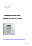
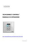
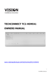
TECHCONNECT CONTROL3 OWNERS MANUAL www.visionaudiovisual.com/techconnect/tc2-ctl3 1 TC2-CTL3_manual_en DECLARATION OF CONFORMITY Where applicable Vision products are certified and comply with all known local regulations to a ‘CB Certification’ standard. Vision commits to ensure all products are fully compliant with all applicable certification standards for sale in the EU and other participating countries. The product described in this owner manual is in compliance with RoHS (EU directive 2002/95/EC), and WEEE (EU directive 2002/96/EC) standards. This product should be returned to the place of purchase at the end of its useful life for recycling. WARNINGS CAUTION: TO REDUCE THE RISK OF ELECTRIC SHOCK DO NOT REMOVE COVER (OR BACK). NO USER-SERVICEABLE PARTS INSIDE. REFER SERVICING TO QUALIFIED SERVICE PERSONNEL. The lightning flash with arrowhead symbol, within an equilateral triangle, is intended to alert the user to the presence of uninsulated “dangerous voltage” within the product’s enclosure that may be of sufficient magnitude to constitute a risk of electric shock to persons. The exclamation point within an equilateral triangle, is intended to alert the user to the presence of important operating and maintenance (servicing) instructions in the literature accompanying the appliance. WARNING: TO REDUCE THE RISK OF FIRE OR ELECTRIC SHOCK, DO NOT EXPOSE THIS APPLIANCE TO RAIN OR MOISTURE. All products are designed and imported into the EU by ‘Vision’ who is wholly owned by ‘Azlan Logistics Ltd.’, Registered in England Nr. 04625566 at Lion House, 4 Pioneer Business Park, Clifton Moor, York, YO30 4GH. WEEE Registration: GD0046SY DECLARATION OF ORIGIN All Vision products are made in the People’s Republic of China (PRC). 2 TC2-CTL3_manual_en USE ONLY DOMESTIC AC OUTLETS Connecting the unit to an outlet supplying a higher voltage may create a fire hazard. HANDLE THE POWER CORD WITH CARE Do not disconnect the plug from the AC outlet by pulling the cord; always pull the plug itself. Pulling the cord may damage it. If you do not intend to use your unit for any considerable length of time, unplug the unit. Do not place furniture or other heavy objects on the cord, and try to avoid dropping heavy objects on it. Do not tie a knot in the power cord. Not only could the cord be damaged, but a short circuit could also be caused with a consequent fire hazard. PLACE OF INSTALLATION Avoid installing this product under the following conditions: • Moist or humid places • Places exposed to direct sunlight or close to heating equipment • Extremely cold locations • Places subject to excessive vibration or dust • Poorly ventilated places Do not expose this product to dripping or splashing. DO NOT PLACE OBJECTS FILLED WITH LIQUIDS ON OR NEAR THIS PRODUCT! MOVING THE UNIT Before moving the unit, be sure to pull out the power cord from the AC outlet and disconnect the interconnection cords with other units. WARNING SIGNS If you detect an abnormal smell or smoke, turn this product off immediately and unplug the power cord. Contact your reseller or Vision. PACKAGING Save all packing material. It is essential for shipping in the event the unit ever needs repair. IF ORIGINAL PACKAGING IS NOT USED TO RETURN THE UNIT TO THE SERVICE CENTRE, DAMAGE IN TRANSIT WILL NOT BE COVERED BY WARRANTY. 3 TC2-CTL3_manual_en FRONT AND REAR PANELS 3 2 6 4 1 7 8 9 5 1. 2. 3. 4. 5. 10 Learn Confirmation LED (green) Learn Mode LED (red) IR Receiver Internal IR Blaster / Emitter Function Buttons 6. RS-232 7. PWR in (12V 0.5A) 8. 12V Trigger out 9. RS-485 10. IR out BUTTONS 1 2 3 4 5 6 4 TC2-CTL3_manual_en CONTROL OPTIONS IR Techconnect Control learns and replicates codes sent from a device’s infrared remote control. An IR emitter integrated into the front panel is adequate for small rooms. For larger rooms three external wired IR emitters are included – one with a 10m cable, and two without cables. Techconnect Minijack cables are suitable to extend these. NOTE: There is no theoretical cable length limit on IR cables. NOTE: Remote controls which come with projection screens are often RF – not IR. To control these screens use the 12v trigger. RS-232 Professional control format used to control a variety of devices including projectors. More reliable than IR and uses two-way communication with the control device to confirm commands has been received. Requires 3-core cable. NOTE: If using RS-232 the TC2-CTL3 needs to be mains-powered. 12v Trigger Simple trigger voltage commonly used to activate projection screens. Requires 2-core unshielded cable. NOTE: If using 12v Trigger the TC2-CTL3 needs to be mains-powered. RS-485 Using the same codes as RS-232, this protocol offers longer cable distances of around 100m, and only requires 2-core cable. Few AV devices can decode RS-485. If using an additional Control module to extend the keypad this terminal is used to connect the slave module to the master. NOTE: If using RS-485 the TC2-CTL3 needs to be mains-powered. 5 TC2-CTL3_manual_en Note: Tx is normally wired to Rx. Extron requires you to wire Tx to Tx. 6 TC2-CTL3_manual_en INSTALLATION 1. FIT LABELS Use flat-head screwdriver to unclip clear button covers, then apply labels as shown: 2. SELECT POWER SOURCE The control module is set to be powered by mains power by default. If you choose to power with 2 x AAA batteries (not included) move switch inside the battery compartment to BATT. NOTE 1: If powered by batteries buttons will only light when pressed. NOTE 2: If powered by mains ensure batteries are not left in device. 3. CONNECT CABLES Connect appropriate cables and fit the module into the surround. In very simple installations it may not be necessary to connect any cables. 7 TC2-CTL3_manual_en SIMPLE MODE PROGRAMMING Appropriate for controlling one IR device only, e.g. projector. 1. PUT DEVICE INTO LEARN MODE Press and hold buttons 3 and 4 (middle buttons). The learn LED on the front panel will turn red and stay on. 2. PRESS BUTTON TO ASSIGN CODE TO Press function button on the front panel which the incoming code will be assigned to. One code can be assigned to each button. 3. TEACH CODE Point remote control at the front panel of Control module. Press and hold the button on the remote until the green confirmation LED flashes. If red LED flashes it has failed to learn the code. Try again. NOTE: Remote control should be 100mm from IR receiver and not held at an angle. Shield from ambient light. 4. REPEAT The device will revert back to normal mode once it has learnt a code. Repeat steps above to program other buttons. BUTTON 2 Automatically sends code twice. Suitable for projector off. This can be disabled with the computer software. BUTTON 5/6 Sends codes repeatedly when held down. Suitable for volume control. This can be disabled with the computer software. 8 TC2-CTL3_manual_en ADVANCED MODE PROGRAMMING NOTE: Device must use mains-power for these advanced functions. Use when you need to Program multiple codes to each button Use RS-232 or 12v trigger Add an extension keypad Program scheduled actions Duplicate to multiple devices 1. LOAD SOFTWARE ONTO PC Download from Vision’s website: www.visionaudiovisual.com/techconnect/tc2-ctl3 2. CONNECT CONTROL MODULE VIA USB In the battery compartment there is a standard USB-B mini connector. (USB cable not included) The software can be used without a control module connected, but if learning IR codes you will need to connect a control module. 3. LAUNCH SOFTWARE You can create a new program, edit program saved on PC, or edit program saved on device. If an extension keypad is used all code will be saved on the master device. The slave device is connected to the master via the RS485 terminal. To find firmware version of your device click “Read CTL3 Time” 9 TC2-CTL3_manual_en 4. START BY ASSIGNING CODES click a button on the image. This window allows you to set the codes for that button 1. Repeat: when you hold the button down the codes are repeatedly sent Sequential: 1st press sends command 1, 2nd press sends command 2, etc. Simultaneous: All commands are send at the same time Select RS-232 / IR / 12V Note: it is not possible to set a delay for 12v triggers 5. SELECT EXISTING CODES If codes are already in the library then select the device and function in the drop-down menus. The code will appear. NOTE: The software contains a pre-set library of RS-232 codes. When you add new codes and sync and software, those new codes become available to all users when they sync 10 TC2-CTL3_manual_en 6. SET UP NEW CODES select “Add New” in any of the device columns. A new window appears: a. Type over existing text in Device / Brand / Model fields. b. RS-232 only: Baud Rate and Parity settings are normally unchanged. The projector manual will advise if they need to be changed. c. Type over existing text in Function fields and enter code. 11 TC2-CTL3_manual_en d. If adding IR codes a learn button will be to the right of each code. i. Connect a TC2-CTL3 to PC with a USB cable. ii. Press learn then wait until the red LED lights on the module iii. Point original remote at front of module and press and hold button iv. Once you have finished the button will be blue to show codes are allocated. Note: External power is not required for the module. Set power switch to “PWR”. e. The save button will not un-grey until all fields are complete. Must type a model name before Save is available. 12 TC2-CTL3_manual_en f. Click Save. You will have just created a list of new codes, so you need to assign a specific new code to the button using the drop-down menus. Note: Each button can be assigned up to three of same type of codes e.g. 3 x IR, 3 x RS232, 3 x 12v. 7. EDIT CODES Click on edit. You can only edit codes that have been created by users. The preset library Vision includes cannot be modified. 8. SCHEDULE LAST If setting up the scheduling function do this last. All of the codes have been learnt first. 13 TC2-CTL3_manual_en TROUBLESHOOTING If your system is not operating properly, please refer to the following information. If the problem persists, disconnect from power and contact your AV reseller immediately. Problem Correction No LED when buttons pressed Module fails to learn the code Module learns code but doesn’t control the projector If powered by batteries make sure switch under batteries set to BATT or PWR as appropriate Replace batteries. Voltage must be higher than 2.8V Check mains power connection (if using). If using mains power remove batteries Make sure codes have been learnt Make sure the original remote is 50mm away from the IR receiver on the top/front of the module, and at 90 degrees Make sure the original remote has fresh batteries. Hold down the button on the original remote for longer and release only after the green LED lights on the module Re-program the buttons. If you programmed in simple mode try programming in advanced mode Use external IR blaster Check IR blaster cable to make sure it hasn’t been damaged 14 TC2-CTL3_manual_en SPECIFICATIONS PRODUCT DIMENSIONS: 71 x 42 x 31mm (length x width x height) PRODUCT WEIGHT: 63 grams CONSTRUCTION MATERIAL: Plastic COLOUR: White POWER SUPPLY: 100-240v AC 50/60Hz 12 volt / 0.5 amp Transformer integrated into plug. Includes interchangeable plugs: UK/EU/US/AU. DC tail length: 4m. Transformer dimensions: 66 x 43 x 30mm POWER CONSUMPTION Static: <= 5uA Sending: <= 20mA Copying: <= 10Ma COMPLIANCE: RoHS, WEEE & CE Compliant ACCESSORIES INCLUDED 5 x Blanking buttons 1 x Labels 1 x Single-Gang Techconnect Backbox 1 x Single-Gang Techconnect Surround 1 x IR Blaster with 150mm cable (terminated with female minijack) 1 x IR Blaster with 10m cable WARRANTY This product comes with a 2-year return to base warranty, effective from the date of purchase. This warranty applies only to the original purchaser and is not transferable. For the avoidance of doubt, this will be taken from the information held by the appointed national distributor at the point of sale. If the product is DOA (dead on arrival), you have 21 days from purchase date to notify the national distributor via your AV reseller. The liability of the manufacturer and its appointed service company is limited to the cost of repair and/or replacement of the faulty unit under warranty, except for death or injury (EU85/374/EEC). This warranty protects you against the following: • Failure of any components, including the power supply. • Damage when the product is first removed from its packaging if reported within 24 hours of purchase. If you find you do have a problem with this product, you should contact the AV reseller you purchased this product from. The original purchaser is responsible for shipment of the product to the manufacturer’s appointed service centre for repair. We will endeavour to return repaired units within 5 working days, however this may not always be possible, in which case it will be returned as soon as practicably possible. In line with our WEEE commitments, the manufacturer endeavours to replace the faulty parts of the product rather than replacing the whole unit. This warranty does not protect this product against faults caused by abuse, misuse, incorrect installation, unstable or faulty power input, which might be caused by ignoring the guidelines set out in this manual. LEGAL DISCLAIMER: Because we are committed to improving our products, the details above may change without prior warning. This User Manual is published without warranty and any improvements or changes to the User Manual necessitated by typographical errors, inaccuracies of current information, or improvements to programs and/or equipment, may be made at any time and without notice. Such changes will be incorporated into new editions of the User Manual. 15 TC2-CTL3_manual_en