1
®
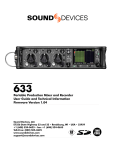
442
Field Mixer
User Guide and
Technical Information for
442 and 442 Nordic Field Mixers
web site version posted April 21,2003
Sound Devices, LLC
300 Wengel Drive
Reedsburg, WI 53959 USA
phone: (608) 524-0625
fax: (608) 524-0655
www.sounddevices.com
© 2002 Sound Devices, LLC. All Rights Reserved.
442
User Guide and Technical Information
SOUND DEVICES, LLC
Welcome to the 442 Field Mixer
Developed with input from the industry’s top audio engineers, the 442 Field Mixer encompasses the audio performance, feature set, and mechanical construction demanded by those who rely on audio gear for their livelihood. The 442 contains four high-performance microphone preamplifiers, many outputs, and flexible monitoring.
Its inputs and outputs, including direct outputs per channel, make the 442 at home in small “run-and-gun” applications as well as large, multiple input productions.
The 442 incorporates a complete feature-set into a compact, functional design. All controls are accessible on its
three main surfaces; no hidden controls. The high-efficiency circuitry allows the mixer to run from either four
internal AA batteries or external 5-18 VDC.
The 442, like all Sound Devices professional audio products, is designed to withstand the physical and environmental extremes of field production. Its compact mechanic construction strikes the perfect balance between
access to all functions, uncluttered design, and durability.
The 442 has an extensive feature list including:
✓
✓
✓
✓
✓
✓
✓
✓
✓
✓
✓
✓
✓
Maximum of 84 dB of gain
Premium Lundahl input transformers
Custom-wound output transformers
Distortion-canceling output driver circuitry
Sealed, conductive plastic faders
T-power or 48 V or 12 V phantom per channel
Sweepable high-pass per channel 80-240 Hz,
12 dB/oct.
Pop-up knobs for roomy mixing surface
Dynamic range > 115 dB
5 to 50kHz bandwidth (-1 dB)
Two separate monitor returns
Input limiters
Output limiters
✓ Comm mic function
✓ 'Ear-saver' tone oscillator/ headphone monitor
✓ 40 segment, three-color peak+VU meter, sunlight
viewable
✓ PFL per channel
✓ Direct outs per channel
✓ Two master output pairs, transformer isolated
✓ Powered from 4 "AA" batteries
✓ 5-18 V external power
✓ Extensive headphone monitoring
✓ Gain trim per channel, front panel
✓ Pulsing left output tone function
✓ Setup menu for extensive customizing
Table of Contents
Front Panel . . . . . . . . . . . . . . . . .4
Input Panel . . . . . . . . . . . . . . . . .5
Output Panel . . . . . . . . . . . . . . .6
Input Channels . . . . . . . . . . . . . .7
Outputs . . . . . . . . . . . . . . . . . . . .9
Output Limiters . . . . . . . . . . . . .10
Mix In . . . . . . . . . . . . . . . . . . . .10
Metering . . . . . . . . . . . . . . . . . .10
www.sounddevices.com/442
Headphone Monitoring . . . . . . .11
Powering . . . . . . . . . . . . . . . . .12
Tone/Slate Mic . . . . . . . . . . . . .13
Accessing User Setups . . . . . .13
Specifications . . . . . . . . . . . . . .14
Block Diagram - Ins and Outs .16
Block Diagram - Monitoring . . .17
Approvals/Warranty . . . . . . . . .18
Appendix
Appendix
Appendix
Appendix
Appendix
A - 442 Nordic . . . . .19
B - Accessories . . . .19
C - Setups (v 5) . . . .20
D - Setups (v 3&4) . .21
E - Setups (v 2) . . . .22
The Sound Waves logo is a trademark of Sound Devices, LLC ® Reg. U.S. Pat & Tm. Office.
page 2
442
User Guide and Technical Information
SOUND DEVICES, LLC
Quick Start Guide
For those familiar with field mixers or mixing consoles, this "Quick Start Guide" highlights basic functionality to
begin operating the 442.
Powering
To power the 442 and get it ready for operation:
1. Insert four AA batteries into the battery compartment. INSERT WITH THE POSITIVE (+) SIDE FIRST.
2. Or, connect external DC power (5 - 18 VDC) to the unit's DC connector.
3. Slide the power switch to the intended power source.
4. View battery level by depressing the battery check button.
Input Channel Setup
To set up a gain level for an input channel:
1. Connect a signal source (microphone or line level signal) to a channel input connector.
2. Select the input type - MIC or LINE level.
3. Activate Phantom or T-powering, if required by the microphone.
4. Set the Channel Fader to the 0 (unity) position.
5. Adjust the Channel Pan for the appropriate position.
6. Adjust the High-Pass filter as needed.
7. Place the Master Gain control to the 0 (unity) position.
8. Adjust the Channel Gain/trim control for the required level.
9. Verify that there is signal present on the output meter.
Output Connection
To connect to the 442 master outputs:
1. Connect to the XLR output of the 442.
2. Select the output type - MIC, -10, or LINE level.
3. Verify that the destination input is receiving signal.
Headphone Monitoring
1.
2.
3.
Connect headphones to the headphone connector on the output panel.
Select the ST position on the headphone selection switch to listen to stereo mixer program.
Monitor audio in the headphones.
Metering
1.
2.
3.
View the master output level on the LED output meter.
Toggle between VU, PPM (Peak), or combined VU/PPM metering with the PK/VU button.
Adjust the meter brightness among its intensities with the meter brightness button.
Limiting
1.
2.
3.
Activate the input and output limiters by engaging the front panel switch - either stereo linked or dual mono.
Note limiting activity via the limiter LEDs and the output level.
Adjust the output limiter threshold and input limiter availability in the Setup Menu (see Appendix).
www.sounddevices.com/442
page 3
442
User Guide and Technical Information
SOUND DEVICES, LLC
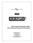
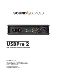
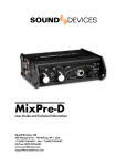
Front Panel Descriptions
1
3
2
5
4
7
6
8
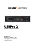
1. Gain
Controls the gain of the microphone preamp.
Range is from +22 dB to +60 dB to accomodate
different input sources. Can be thought of as a
"coarse" gain adjustment.
2. Channel Fader
Controls a channel's gain. Ranges from 'off' to +15
dB. Nominal setting is in the middle (0 dB). Can be
thought of as a "fine" gain adjustment.
3. Channel Pan
Controls the Left/Right balance of the input signal
to the outputs. Signal is 3 dB greater than center
position when panned hard right or left.
4. LINK LED
Indicates that channels 1 and 2 are linked as a
stereo pair, set via the Link Switch on the input
panel.
5. Channel 2 Polarity Reverse
Reverses the polarity of input channel 2.
6. PFL (Solo)
Sends the channel signal to the headphones for
troubleshooting and gain set-up. Does not affect
master output signal at all.
7. Peak LED
Indicates that the input signal is 3 dB from clipping.
Indicates that Gain is set too high if LED comes on.
8. High-Pass Filter
Adjusts corner (-3 dB) frequency of high-pass filter.
Fully counter-clockwise (detented) removes the
high-pass filter. Range is 80 Hz to 240 Hz,
12dB/oct to 6 dB/oct.
9. Input Limiter LED
Illuminates orange in proportion to the amount of
input limiting. Indicates that Gain Trim is set too
high if significant limiting is occurring.
www.sounddevices.com/442
11
9
10
13
12
15
14
17
16
19
18
21
20
22
10.Slate Mic / Tone Oscillator
Activates the slate microphone in the left position
(momentary) and activates the tone oscillator in the
right position (latched).
11.Limiter Switch
Activates both input and output limiters. Input limiters can be defeated in the Setup Menu. ON = output limiters are not linked to each other. LINK = output limiters are linked to each other for stereo outputs.
12.Master Gain
Controls overall level of signals to both left and right
outputs.
13.Meter Brightness
Adjusts the overall mixer LED brightness level
among four intensities (or meter off).
14.Meter Ballistics Selection
Selects among output meter ballistics - VU, PPM
(Peak), combined VU/PPM, or VU-PPMHold (see
Metering). Hold down while powering to access the
Setup Menu.
15.Monitor Selection Switch
Selects the audio source sent to the headphones.
Off . . . . .no signal
L . . . . . .left output only to both ears
R . . . . . .right output only to both ears
M . . . . . .summed (mono) left and right to both ears
ST . . . . .stereo - left output to left ear and right output to right ear
A . . . . . .stereo Return A to headphones
B . . . . . .stereo Return B to headphones
A|B . . . .Return A (summed) to left ear, and Return B (summed)
to right ear
MS L . . .decoded MS Left to both ears
MS R . . .decoded MS Right to both ears
MS ST . .decoded MS Stereo to headphones
page 4
442
User Guide and Technical Information
SOUND DEVICES, LLC
16.Battery Level
Views the battery level on the output meter. Left
meter indicates internal battery level, right meter
indicates external battery level. See POWERING.
20.Monitor Return A|B
Allows for quick selection of return audio signals to
be sent to the headphones. Function can be modified in the Setup Menu.
17.Headphone Gain
Adjusts the overall headphone gain.
21.Output Limiter LEDs
Illuminates orange in proportion to the amount of
output limiting. Indicates that Master or Faders are
set too high if significant limiting is occuring.
18.Output Meter
40 segment output meter. Markings indicate output
level (at line-level) in dBu for Peak setting. For VU
setting, markings indicate Volume Units. See
APPENDIX A for 442N scale.
22.Power Switch
Selects internal or external power source for the
mixer.
19.Power LED
Illuminates when unit is powered. Flashes when
power supply is low. With external DC supply the
LED flashes at select voltage. See POWERING.
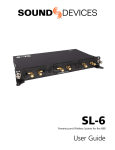
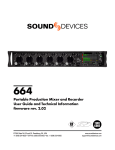
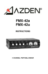
Input Panel Descriptions
23
25
24
23. XLR Inputs
Transformer-balanced channel inputs. Can be
unbalanced by grounding pin-3 to pin-1 of the
XLR connector. Pin-1 = Ground; pin-2 = 'Hot'; pin3 = 'Cold'.
24. Mic/Line Channel Switch
Selects the input level of its associated input connector.
25. Phantom/DYNamic/T-Power Selection
Selects the microphone powering type of the
associated channel.
NOTE: Use T-Powering ony for T-Powered
microphones.
27
26
29
28
27. Phantom Voltage Selection
Selects either 48 V or 12 V phantom voltage for
the input channels.
28. 1 + 2 LINK
Groups channels 1 and 2 as a stereo pair. ON
selects a L/R stereo pair, MS selects a Mid-Side
stereo pair. See Stereo Link for more information.
29. RTN A and RTN B Level
Adjusts the input sensitivity for the Return A and
Return B signals. Useful for balancing levels when
toggling between program and return audio.
26. TA3-type Channel Direct Outputs
Balanced, line level channel output. Signal is prefader, post-trim, post-input-limiter, post high-pass.
Selectable Line or Mic level output via User
Setup. Pin-1 = Ground; pin-2 = 'Hot'; pin-3 =
'Cold'. Can be used unbalanced with pin-2 and
ground.
www.sounddevices.com/442
page 5
442
User Guide and Technical Information
SOUND DEVICES, LLC
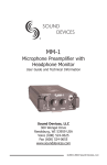
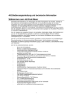
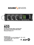
Output Panel Descriptions
35
33
30
40
36
39
38
37
34
30. XLR Master Outputs
Transformer-balanced ouputs. Pin-1 = Ground;
pin-2 = 'Hot'; pin 3 = 'Cold'. Can be unbalanced by
grounding pin-3 to pin-1 of the XLR connector.
31. XLR Output Level
Sets the nominal output level for the XLR Master
Outputs to Mic, Tape (-10), or Line levels.
32. TA3-type Master Outputs
Selectable Line (factory default) or Mic level output set in Setup Menu. Pin-1 = Ground, pin-2 =
'Hot', pin-3 = 'Cold'. Can be used unbalanced with
pin-2 and ground.
33. Hirose Multi-Pin Output (Return A)
Multi-pin connector includes second master output (on separate winding from XLR outputs). Also
includes unbalanced stereo Return A. (See block
diagram for pin out.)
34. Hirose Multi-Pin Hirose Output Level
Selects output level for the Hirose Multi-Pin
Output to Mic, Tape, or Line Level.
35. Tape Output(s) / Mix Out
Unbalanced stereo outputs on 3.5 mm and TA3type connectors. For TA3, pin-1 = Ground, pin-2 =
Left, pin-3 = Right. For 1/8", sleeve = Ground, tip
= Left, ring = Right. Also used to link to the Mix In
to add inputs to a 442.
36. Mono Mic Out
1/8-inch, mono, mic level connection designed to
connect to wireless IFB transmitters or transcription recorders. Unbalanced. Tip = Hot, sleeve =
Ground.
www.sounddevices.com/442
31
32
31
41**
37. Return B Input
Unbalanced stereo TA3-type or 3.5 mm input connectors for Return B audio. TA3: Pin-1 = Ground,
pin-2 = Left, pin-3 = Right. 1/8": Sleeve = Ground,
tip = Left, ring = Right.
38. Headphone Outputs
1/4-inch and 3.5 mm stereo connectors can drive
headphones from 8 to 2000 ohm impedances to
required monitoring levels.
39. Mix In
An input to the master bus designed exclusively
to link another 442, MixPre, or MP-2 to the 442
for additional inputs. Pin-2 = Left, pin-3 = Right,
pin-1 = Ground. Shell of TA3 connector must be
grounded to pin-1 to open connection.
40. Battery Compartment
Holds four AA batteries required for internal powering. Accepts alkaline and lithium cells or NiHM
rechargeable cells.
41. DC Input
Accepts DC voltages from 5 - 18 V for mixer powering. Four-pin Hirose connector is wired pin-4
positive (+), pin-1 negative (-). Ext DC is completely isolated (floating) from the rest of the circuitry.
**
Note
Early versions (s/n < 0303) of the 442 use a
coaxial DC power connector with tip (+) and
sleeve (-).
page 6
442
User Guide and Technical Information
SOUND DEVICES, LLC
Input Channels
he inputs of the 442 consist of four, full-featured
microphone preamplifiers. Each channel has a
wide gain range to accommodate nearly all signal
types. The 442 accepts signals ranging from low-sensitivity ribbon and dynamic microphones to medium
level wireless and condenser mic outputs up to "hot"
line levels.
T
442 input channels are transformer-balanced. The isolation characteristics of transformers are superior to
other balancing techniques for the hostile and uncontrolled environments of field production. Transformers
provide galvanic isolation from the driving source,
meaning there is no direct electrical connection.
Signals are "transformed" magnetically. The input
transformers in the 442 use premium magnetic core
material to achieve high signal handling capability
(especially at low frequencies) while keeping distortion
to a minimum. Because of their inherently high common mode impedance, transformers are unrivaled by
any other type of input for common-mode noise rejection.
The inputs of the 442 can be used as either balanced
or unbalanced connections. When unbalancing,
ground pin-3 to pin-1. There is no change in gain
between unbalanced and balanced connections into
the 442.
Mic/Line Level Selection
The Mic/Line switch is used to select the input level for
the channel. Taking into account all available gain
stages, the 442 has up to 84 dB of available gain from
mic input to line output. When in the LINE position, the
input channel sensitivity is reduced by 40 dB.
Gain
Like traditional mixing consoles, the 442's microphone
preamp gains are set via the Gain control. The Gain,
or trim, adjusts the input sensitivity of the channel
input so that the channel fader can be set to operate
in a usable range. Once set, the Gain is typically kept
at the set level and all mixing is done on the Channel
Fader. The Gain adjustment features a pop-up knob so
that it can be adjusted easily and then hidden from the
mixing surface.
Faders
While both the Gain and the Fader control the gain of
a given channel, the Fader is the primary channel
level control. The Gain can be thought of as a "coarse"
www.sounddevices.com/442
gain adjustment to be adjusted during setup, and the
Fader is a "fine" gain adjustment to be adjusted while
recording. With a properly set up Gain, the Fader can
be set to a nominal 0 (unity) level. With the Fader at
unity, the dynamic range of the mixer is maximized.
There is a wide range of gain control for the input,
allowing for smooth gain changes with adequate control of attenuation and gain.
Phantom Powering
The 442 can provide phantom power to each channel
and is selected per channel. The 442 can provide up
to 10 mA to each input at 48 V, sufficient for the most
power-hungry condenser microphones. When acceptable, using 12 V phantom is recommended to extend
battery runtime. Many microphones do not require 48
V phantom and can be properly powered from 12 V
phantom power. The phantom voltage level is globally
selected for all inputs - either 12 V or 48 V.
The 12 V/48 V phantom voltage switch is located on
the input panel.
Phantom Basics
Phantom powering is a method of providing power to
microphones by applying a voltage to the microphone
using the same wires that carry the audio signal.
Phantom power is produced by the 442 for microphones that require power.
Condenser microphones require power for various
parts of their operation, including impedance converters, preamplifier circuitry, and in some cases, to polarized microphone capsules. Phantom powering utilizes
a fixed DC voltage between 12 and 48 volts. This voltage is resistively applied to pin-2 and pin-3 of an XLR
connector relative to pin-1. (Note that as there is no
voltage difference between the signal pins -2 and -3,
a dynamic mic can operate just fine in the presence of
phantom powering.)
Microphones draw differing amounts of current based
on their design. Many phantom-powered mics will
operate at 12 V with no difference in performance as
compared to operating off of 48 V. As the mics draw
the same current no matter what the phantom voltage,
operating at 48 V consumes four times the power as
12 V with no performance gain! This excess power
draw can make a significant difference in battery life
and is the reason that the 442 allows the user to
select phantom voltage.
page 7
442
User Guide and Technical Information
It is generally good practice to turn off phantom power
when not using a phantom powered mic, as phantom
power can capacitively couple noise into the mic
inputs with poor mic cables. Also, turn phantom power
off when using ribbon microphones since an improperly wired cable can permanently damage the microphone.
The DYN (dynamic) position applies no voltage to the
microphone input.
T-Powering
T-powering is a microphone powering scheme used by
several European condenser microphone manufacturers. Today, T-powered microphones are not as common as phantom microphones, but many are still in
regular use. Unlike phantom power, T-power resistively
applies 12 V between the signal pins -2 and -3. The
442 provides selectable T-power for each input. The
442 provides positive T-power, where pin-2 on the
XLR-3 connector has +12 volts relative to pin-3. When
using "red dot" T-powered microphones (reverse polarity T-power) use a polarity-reversing adapter on the
input, otherwise damage to the microphone may
occur. Do not apply phantom power to T-powered
microphones.
NOTE: Phantom and T-powering are not interchangeable. Use T-powering only for T-powered microphones.
High-Pass Filters
Each channel of the 442 has an adjustable high-pass
filter. High-pass (or low-cut / low roll-off) filters are useful for removing excess low frequency energy in audio
signals. Wind noise is a common unwanted low frequency signal and a high-pass filter is effective for
reducing wind noise. For most audio applications
engaging the high-pass filter is beneficial, since little
useable audio information exists below 100 Hz, especially for speech reproduction.
The 442's high-pass circuit features an adjustable corner (- 3 dB) frequency over a range from 80 Hz to 240
Hz. Below 80 Hz, the filter's slope is 12 dB/octave. At
higher corner frequency settings, the slope is 6
dB/octave, and then below 80 Hz, it increases to 12
dB/octave (see Specifications). The purpose for this
compound slope is to give additional roll-off at the 80
Hz setting to reduce wind noise and rumble. The higher settings can be used to counteract proximity effect
of directional mics where a more gentle slope is desirable. The 442's high-pass circuit is unique because of
its placement before any electronic amplification. Most
mixer's high-pass circuits are placed after the mic pre-
www.sounddevices.com/442
SOUND DEVICES, LLC
amp, where all of the high-energy low-frequency signals get amplified. By virtue of the 442's circuit cutting
the low-frequency signals before amplifying, higher
headroom is achieved in presence of signals with a lot
of low-frequency energy.
Where possible, attempt to equalize at the sound
source with microphone selection, use of windscreens,
microphone placement, and onboard microphone filtering. Many microphones have on-board high pass filters, and the high-pass filters on the 442 can be used
in conjunction with the microphone's filters to increase
the filter's slope.
The filter can be removed from the circuit completely
by moving the high-pass control fully counterclockwise. The high-pass features a pop-up knob so that it
can be adjusted easily and then hidden from the mixing surface.
Pan Controls
The pan control routes an input channel signal anywhere between the Left and Right output. The 442
uses constant loudness pan controls, meaning that the
signal is 3 dB louder at the full-right or full-left position
relative to the center position. For most applications
the channel will be panned either full left, full right, or
to the center; the 442 features excellent "off-attenuation" of the channels in the hard- left and right positions. The pan pot has a detent in the center position,
and is calibrated at Sound Devices for a maximum difference of +/- 0.1 dB between the left and right output
in this position. Since pan is not often used after channel setup, the pan pot is on a pop-up knob so it can
be hidden from the mixing surface during normal operation.
Channel Limiters
The channel limiter acts solely as a "safety" limiter,
and is enabled when the output limiters are enabled
via the "LIM" switch on the front panel. (See Setup
Menu to defeat Channel Limiters entirely.) In normal
operation, with a properly set gain structure the
threshold of the channel limiter will not be reached. If
extremely high input signal levels exist, such as in high
SPL environments or with misadjusted settings, the
channel limiter(s) will activate to prevent the input
channel from clipping. Without a channel limiter, high
signal conditions would overload the channel and
cause distortion. It is recommended that the channel
limiters be used at all times. Below the set threshold
(just below clipping), the limiter does not affect the
sound in any way.
page 8
442
User Guide and Technical Information
When input channels 1 & 2 are linked as a stereo pair,
their channel limiters also link to perform the same
gain reduction to both channels equally. Each channel
has an orange limiter LED which illuminates in proportion to the amount of limiting. If the orange LED for a
channel comes on substantially, it is recommended to
turn down the Gain.
Peak LEDs
Each channel has an indication of peak signal activity.
When a channel approaches 3 dB below its clipping
level, the red Peak LED illuminates. If the red Peak
LED for a channel comes on often, it is recommended
to turn down the Gain.
Polarity Reversal - Channel 2
Engaging the polarity reverse switch inverts the polarity of channel 2. Polarity reversal is often used to quickly reverse the stereo field in MS recording. The normal
position is OFF, with polarity reversal occurring when
the switch is in the Θ position.
NOTE: Do not change the polarity of channel two during recording, since a pop occurs when the switch
changes states.
Stereo Link ON - Channels 1 and 2
When Stereo Link is set to ON, input channels 1 and 2
are turned into a single, stereo pair controlled by chan-
SOUND DEVICES, LLC
nel one's fader. The Pan control for channel 1
becomes a balance control between left and right. The
Fader and Pan on channel 2 are disabled. Channel 1
and 2's trim level and high-pass filters remain active on
their respective signals. When linked, channel 1 & 2's
channel limiters are also linked.
Stereo Link MS - Channels 1 and 2
When Stereo Link is set to MS, input channels 1 and 2
are linked as an MS pair where input 1 is the Mid signal and input 2 is the side signal. The Channel 1 Pan
Control functions as a left/right balance control for the
matrixed MS signal. The Fader and Pan on channel 2
are disabled. The Gain Trims and high-pass filters still
act individually. The Gain Trim controls for inputs 1 and
2 can be used to vary the Mid and Side levels respectively. When linked, channel 1 and 2's channel limiters
are also linked.
PFL (Channel Solo Monitoring)
When the momentary PFL switch is activated the
channel audio is routed (in mono) to the headphones.
This signal is post-trim, post high-pass, post-limiter,
and pre-fade. From the factory the left meter indicates
the signal level of the channel. PFL monitoring does
not disrupt audio sent to the master outputs. The PFL
metering function can be deactivated in the Setup
Menu.
Outputs
The 442 is a two-bus mixer with several outputs essential for multi-camera, multi-source productions.
Because each input can be continuously panned from
left to right, the mixer can be used with either two
mono buses or with a single stereo bus.
Master Gain Control
A single master gain control adjusts the overall output
level of the left and right outputs. The gain range of the
Master is from complete attenuation (master outputs
off) to +6 dB of gain. For most applications the Master
control should be set at the unity gain (0) position. The
master gain is on a pop-up knob so it can be set and
hidden from the main surface so inadvertent adjustments are avoided.
Master Outputs - XLR and Hirose Multi-Pin
former-balanced connections each driven from their
own transformer windings for excellent isolation.
Additionally, the outputs can independently be set to
Line, Tape (-10 setting, 14 dB of attenuation from
Line), or MIC Level (40 dB of attenuation from Line).
The master outputs are capable of driving long lines.
The multi-pin connector also includes a stereo, unbalanced Return A input for headphone monitoring.
Secondary Balanced Outputs
The TA3-type connectors below the Master XLR pair
are an additional set of master outputs. These outputs
are impedance-balanced (pin-2 is driven and pin-3 is
not) and can be used as either balanced or unbalanced outputs. The output level from the factory is
Line-Level (+4 dBu nominal). This level can be
changed in the Setup Menu to Mic-Level.
The master XLR and Multi-Pin outputs are trans-
www.sounddevices.com/442
page 9
442
User Guide and Technical Information
SOUND DEVICES, LLC
Tape Outputs (Mix Output)
Mono Mic Output
The 442 has an unbalanced, tape level output available on both a locking TA3-type connector and a 3.5
mm connector. These two connectors are resistively in
parallel. Tape outs are typically used to interface with
consumer inputs such as MiniDisc, DAT, and compact
cassette recorders. Tape outputs are isolated from the
main outputs, so any devices connected to these will
have no effect on the master outputs.
The Mono Mic Output is a sum of the two output channels intended for portable transcription recorders. This
signal is mono, Tip/Sleeve, and is a microphone level.
This output can also feed a wireless IFB transmitter.
Output Limiter
With the input and output limiters active, it is nearly
impossible to clip (overload) the 442 mixer. To activate
the 442 limiters, set the front-panel "LIM" switch to
either the LINK or ON positions. See "Channel Limiter"
section for more information on the input limiters.
The output limiters prevent the peak output signal level
from exceeding the set limiter threshold.
The output limiter threshold is set in the
Setup Menu to any level from +4 dBu to
+20 dBu in 1 dB increments (see Setup
Menu). From the factory, the mixer is set to limit the
output signal peak levels to +20 dBu. This assures that
the output of the 442 will not overload inputs that can
accept full line-level signals (+24 dBu peak).
The orange LIM LEDs at the end of the meter scale
illuminate in proportion to the amount of limiting.
LINK or ON?
The output limiters can be selected to act together as
a single limiter controlling both the left and right output
channels equally (LINK) or act as two independent
limiters (ON). The LINK position is recommended
when recording stereo program, so that level changes
are identical for both channels. The ON position is recommended when using the 442 outputs as two separate buses.
Mix Input (linking mixers)
The Mix In connector allows two 442 mixers to be connected for a total of eight input channels. The signal of
all eight input channels are present at the output of
the 442 to which the Mix In connector is connected.
The other 442's outputs will contain only its own four
input channels. To link two 442 mixers, simply connect
the Mix Out of the first mixer to the Mix In of the sec-
ond 442 with Sound Devices XL-1 link cable (included). Alternatively, a Sound Devices MixPre or MP-2
can be connected to the 442's Mix In with the proper
cable. The connector shell of the Mix In TA3 connector
must be grounded to pin-1 of the connector to open
the connection.
Metering
The 442 features a large 40-segment (20 per channel)
LED output meter with selectable ballistics. The meter
uses energy-efficient GaN LED's, which can be
viewed in full sunlight. The 442 output meter is unaffected by shock, temperature, or humidity extremes.
The microcontroller-based output meter provides a
selection of ballistics and lighting intensities.
Meter Ballistics
The output meter can be set to display any of four
types of meter ballistics - VU, Peak, a composite of VU
and Peak, and a composite of VU with Peak hold. The
www.sounddevices.com/442
button labeled PK/VU toggles the ballistics. The meter
button can be pressed any time to change ballistics.
See the Setup Menu for selections.
VU - (Volume Units) meter ballistics correspond closely to how the human ear perceives loudness and provides a good visual indication of how
loud a signal will be. In VU mode, the attack and
decay of the meter signal is 300 mS. While giving a
very good visual indication of how loud a signal will
be, a VU meter gives poor information on actual signal
peaks. In VU mode, the front panel meter labeling is in
volume units. VU meters are always referenced to an
page 10
442
User Guide and Technical Information
actual signal level in dBu, and the 442 VU meter is referenced with 0 VU corresponding to 0 dBu at the LineLevel outputs. If needed, the reference level can be
changed via a User Setup to +4 dBu or +8 dBu.
Peak - Peak-reading ballistics correspond to
actual signal peaks, but don't necessarily correspond
to perceived signal loudness. The peak meter has an
instantaneous attack to display all peaks and a slow
decay to allow the user to see them. Peak metering is
useful when interconnecting to modern audio inputs on
digital equipment, as signal overload can cause immediate distortion. The peak meters front panel markings
are calibrated in peak dBu level at the Line-Level outputs.
VU/Peak - The 442 can simultaneously display
VU and Peak level information. In this mode the perceived loudness (VU) is displayed on a bar graph, and
the Peak signal on a dot above the VU. With this combination the user gets the best of both VU and Peak
metering by seeing the "loudness" of the signal while
observing peaks at the same time.
SOUND DEVICES, LLC
VU/Peak Hold (firmware v. 3+ only) - Similar
to VU/Peak mode, this mode holds the peak level indication for several seconds before releasing. Peak Hold
indicators are useful for metering in applications when
an overload condition is unacceptable.
Meter Lock (firmware v. 3+ only)Simultaneously pressing the battery check and meter
brightness buttons locks the selection of the meter setting. This setting is saved on power down.
Headphone Peak LED
Like the Channel Peak LEDs, the headphone circuit
has an indicator for peak overload. This LED is very
useful, since headphones can often overload before
the mixer overloads. Monitoring without a visual indication of headphone clipping could mislead the operator
into thinking that the output or return feeds are distorted. The Headphone Peak LED also doubles as a clip
indicator for the stereo Return A and Return B signals.
If any of the Return signals clip (after the Return gain
stage), the Headphone Peak LED illuminates.
Headphone Monitoring
The 442 can drive headphones to dangerously high
volumes. Turn down the headphone gain control before
selecting a headphone source to prevent accidental
signal extremes.
Headphone Gain
Headphone Source Selection
Return A and B
The rotary headphone source switch sets the audio
source sent to headphones. The selections available
are:
The Return monitor switch has two positions, A and B.
When switched to the A position, Return A audio is
sent to the headphones, taking precedence over the
Headphone Source selection. Similarly, when toggled
to the B position, Return B audio is sent to the headphones. This switch can change assignments performed in the Setup Menu.
Off . . . . .no signal
L . . . . . .left output only to both ears
R . . . . . .right output only to both ears
M . . . . . .summed (mono) left and right to both ears
ST . . . . .stereo - left output to left ear and right output
to right ear
A . . . . . .stereo Return A to headphones
B . . . . . .stereo Return B to headphones
A|B . . . .Return A (summed) to left ear, and Return B
(summed) to right ear
MS L . . .decoded MS Left to both ears
MS R . . .decoded MS Right to both ears
MS ST . .decoded MS Stereo to headphones
www.sounddevices.com/442
Headphone gain is controlled by a pop up knob to
remove it from the mixing surface.
page 11
442
User Guide and Technical Information
SOUND DEVICES, LLC
Powering
The 442 can be powered from either internal batteries
or externally via DC powering. The internal batteries
can be used as either a primary power source or as a
back-up in the event that external power is removed or
depleted. The power switch selects the power source either internal or external powering. There is a large
enough power reserve to be able to switch back and
forth from one source to the other without interruption
of mixer signal.
The 442 is very power efficient and can run from fourAA alkaline batteries (without phantom) for approximately eight hours. As additional load is placed on the
mixer, battery life is reduced.
Internal Powering
The 442 can be powered via AA-sized batteries of various types. Lithium cells, alkaline, and NiMH rechargeable AA battery types are all popular batteries for internal AA powering. The 442 will achieve longest battery
life with use of Lithium or NiMH batteries.
1. Microphone powering - the main source of extra
442 current draw. (See Phantom Power) 48 V
Phantom can draw copious amounts of current out
of the batteries depending on what model microphone is used. Two phantom powered microphones
draw twice as much current as one. Microphones
vary widely in their current draw depending on type
and phantom voltage applied.
2. Output drive level - higher output drive levels into
multiple, low-impedance inputs increases current
draw.
3. Headphone output circuit - high headphone output levels increase current draw.
Experimentation is recommended to determine battery
life for each individual setup and application.
Chart of Setups for
Battery Metering
External Powering
The 442 can be powered from any DC voltage from 5
to 18 VDC. Pin-4 of the locking, Hirose connector is
positive (+) and pin-1 is negative (-). The external DC
supply is completely isolated (floating) from the rest of
the mixer for easy and safe interconnection to other
external audio gear.
Setting
High LED Flash
Low
Voltage
Point
Voltage
Power
Source
6.0
4.5
4.0
Internal batteries
1
13.0
11.5
11.0
12 V NiCad, NiMH,
Li, etc.
Power Metering
2
17.0
11.5
11.0
Expanded range of
setting #1
The battery check button indicates battery voltages of
internal and external power supplies. The left meter
shows the internal battery voltage and the right meter
shows the external battery voltage. Since many different battery types are available for external use, the
external DC metering can be customized for a given
battery in the Setup Menu.
3
8.5
5.75
5.5
6 V NiM, Li, etc.
4
14.0
11.4
10
12 V Lead Acid
5
7.0
5.7
5.0
6 V Lead Acid
6
17.0
11.5
5.0
Full range of DC
input, w/ cutoff for
12 V NiCad, etc.
Power Consumption
The 442 can vary in the amount of current it draws.
Several functions of the 442 directly affect current draw
in different ways. The following list highlights the larger
current drawing functions (listed from highest to lowest
current draw).
www.sounddevices.com/442
Factory setting.The full length of the meter scale indicates the voltage range of 13 V to 11 V, in 0.1 V increments. Experiment to determine battery runtime.
page 12
442
User Guide and Technical Information
SOUND DEVICES, LLC
Tone Oscillator / Slate Microphone
A single 3-position switch controls both the tone oscillator and the slate microphone.
Tone Oscillator
Tone is used to set gain structure between the 442
and the next device in the signal path. The tone oscillator uses the locking position of the switch.
From the factory, the tone oscillator is set to output a 1
kHz tone at 0 dBu to the outputs (when the outputs
are set to Line level). Tone is also sent at the same
level to the direct outputs. In the Setup Menu, the tone
frequency and output level can be changed. Also, the
tone oscillator can be removed from the direct outputs
or the tone switch can be defeated.
The 442 oscillator contains a unique feature: the
headphones are attenuated by 20 dB when the tone is
active to save the operator's ears. This feature can be
defeated in the Setup Menu.
When the tone oscillator is active, press the battery
check button to cycle between 0 and -20 dB in the left
output. This is helpful to verify left and right channel.
Turning off the tone oscillator or pressing the battery
check button again stops the output cycling.
Slate Microphone
The slate microphone is used to audibly notate scenes
at the mixer location. Its audio performance is not suitable for critical recording applications; it should only be
used for documenting scenes to tape. The slate mic
uses the momentary switch position.
In the Setup Menu, a one second 400 Hz tone can be
set to precede the slate microphone.
The slate microphone signal is sent to all outputs
except the Direct Outs. In the Setup Menu, the slate
microphone can be disabled to prevent unintended
activation.
The slate mic can function as a communication mic in
addition to the normal Slate Mic. This function is normally disabled and is turned on in the Setup Menu. In
this mode, program audio at the right secondary-master TA3 connector is disabled. Instead, the audio from
the slate mic appears at this output when the RTN A/B
toggle switch is actuated. Normal program audio is
unaffected. This function can be used in conjunction
with a Sound Devices MM-1 to create a flexible communications system with a boom operator.
Accessing the Setup Menu
The 442 has 18 available setup options (see Appendix
for setup charts). Setups, while not typically changed
during normal operation, are easily accessed directly
on the front panel.
Enter the Setup Menu
To access the setup menu perform the following steps:
1. Turn off the mixer, if already on.
2. Depress and hold the Peak/VU selection switch while switching
internal power on.
3. The setup mode is now enabled.
The mixer will not pass audio when in the setup menu.
In setup menu the left meter (L) position indicates the
selected setup. The right meter (R) position indicates
the values selected for the Setup. Use the PK/VU button advance from one setup to another. If you pass up
the intended option, you must re-enter Set Up Mode
since you cannot go backward, only forward when
selecting individual setups.
To adjust values, the meter brightness button (left) and
the battery check button (right) allow you to choose
among setup values. Some setups have multiple values while others have only two values.
Example: Change the Tone Oscillator Frequency from the factory
www.sounddevices.com/442
default (1 kHz) to 100 Hz.
1. Enter the setup menu by holding down
the PK/VU button while powering the
mixer.
2. Press the PK/VU button several times until the left meter
Hold while powLED is at the -8 position (see Appendix - SETUP
ering to enter
MENU).
3. To move among parameter values, press the brightness setup menu
LED and battery check LED until the 100 Hz position is selected
(-14 LED).
4. Press the PK/VU button multiple times until the meters perform
their scrolling dance. This sets the parameter into memory.
To save new values to memory, the PK/VU button
must be repeatedly pressed until the last setup is
reached. At that point the meters will scroll and the
new values will be saved to memory.
User Default (v5 firmware only)
A memory location is available to store userdefined default settings. The user default is Hold while powering to
save current settings
helpful to save a new “baseline” of settings as user preset
different than the factory default settings. To
save a user default hold down both the meter brightness
button and battery check button while powering the mixer.
The current settings will be saved as the user default.
These settings can be recalled from the setup menu.
page 13
442
User Guide and Technical Information
SOUND DEVICES, LLC
Specifications
Measurement Settings (unless otherwise specified): Gain controls for the channel being measured at mid point, all
other channel gains fully down; pan controls centered; low-cut off; inputs in 'MIC' position; outputs in LINE position.
Mic input driven with 150 ohm source. Outputs measured with 100k ohm load. Temperature at 25°C.
Maximum Gain, typical (Trim, Fader, Master, Phones, RTN A, RTN B fully up):
XLR Input
MIC Setting
XLR Input
LINE Setting
RTN
A, B
XLR, Multi-pin Outs @ LINE Setting
81 dB
41 dB
-
XLR, Multi-pin Outs @ –10 Setting
67 dB
27 dB
-
XLR, Multi-pin Outs @ MIC Setting
41 dB
1 dB
-
Balanced TA3-type Outs @ LINE Setting
81 dB
41 dB
-
Balanced TA3-type Outs @ MIC Setting
41 dB
1 dB
-
Tape Out, TA3-type and 1/8"
67 dB
27 dB
-
Mono Mic Out
41 dB
1 dB
-
Headphones, ¼" and 1/8"
101 dB
81 dB
30 dB
Frequency Response:
20 Hz - 30 kHz, +0.2, -0.5 dB, -1 dB @ 5 Hz and 50 kHz
typical
Equivalent Input Noise:
-126 dBu (-128 dBV) maximum. (22 Hz - 22 kHz bandwidth, flat filter, trim control fully up)
Input Clipping Level:
0 dBu minimum (trim control fully down)
THD + Noise:
0.007% typical (1 kHz, +4 dBu at line out)
0.09% max (50 Hz - 20 kHz, +18 dBu at line out, fader
fully up)
Output Noise:
-100 dBu (-102 dBV) maximum (22 Hz - 22 kHz bandwidth, flat filter, master gain fully up, faders fully down)
Common Mode Rejection Ratio:
120 dB minimum at 80 Hz, mic input
100 dB minimum at 10 kHz, mic input
Line Output Clipping Level (1% THD):
20 dBu minimum
18 dBu minimum w/600 ohm load
L/R Gain Matching, Mic in to Line Out:
+/- 0.1 dB
Dynamic Range:
115 dB minimum (trim fully down)
INPUTS:
Impedance
(Ohms)
Type
For use with:
Max Input Level
XLR - MIC setting
2k
transformer-balanced
< 600 ohm mics
0 dBu (0.78 Vrms)
XLR - LINE setting
16k
transformer-balanced
< 2k ohm outputs
+40 dBu (80 Vrms)
RTN A, B (3.5 mm/
TA3/Multipin)
20k
unbalanced, stereo
< 2k ohms outputs
+24 dBu (12.4 Vrms)
Mix In
4.2k
unbalanced, stereo
442 Mix Out (1.8k)
+6 dBu (1.5 Vrms)
www.sounddevices.com/442
page 14
442
User Guide and Technical Information
SOUND DEVICES, LLC
OUTPUTS:
Impedance
(Ohms Actual)
XLR, multi-pin - LINE
setting
Type
For use with:
Max Output Level
85
transformer-balanced
>= 600 ohm
inputs
+20 dBu (7.8 Vrms)
XLR, multi-pin - –10
setting
3.2k
transformer-balanced
> 10k ohm inputs
+6 dBu (1.5 V rms)
XLR, multi-pin - MIC
setting
150
transformer-balanced
> 600 ohm inputs
-20 dBu (0.078 Vrms)
TA3-type, LINE setting
1k
impedance-balanced, pin-2 driven
> 3k ohm inputs
+20 dBu (7.8 Vrms)
TA3-type, MIC setting
1k
impedance-balanced, pin-2 driven
> 3k ohm inputs
-20 dBu (0.078 Vrms)
Direct Outs - LINE setting
1k
impedance-balanced, pin-2 driven
> 3k ohm inputs
+20 dBu (7.8 Vrms)
Direct Outs - MIC setting
1k
impedance-balanced, pin-2 driven
> 3k ohm inputs
-20 dBu (0.078 Vrms)
Tape Outs - 3.5 mm
and TA3-type
1.8k
unbalanced, stereo
> 6k ohm inputs
+6 dBu (1.5 Vrms)
Mono Mic Out
150
unbalanced, mono
> 600 ohm inputs
-20 dBu (0.078 Vrms)
Headphones - 3.5 mm
and ¼"
200
unbalanced, stereo
8 - 2k ohm headphones
+20 dBu (7.8 Vrms)
High-Pass Filters:
Sweepable 80 Hz to 240 Hz, 12 dB/oct at 80 Hz,
6 dB/octave at 240 Hz
Audio Connectors:
10-pin Hirose multipin (see pg. 18 for pin assignments) to
mate with Hirose #RM15TD-10P,
TA3M to mate with TA3F-type
Output Limiters:
Affects the outputs of the mixer.
Threshold selectable from +4 dBu to +20 dBu,
1 dB steps, 20:1 limiting ratio, 1 mS attack time,
200 mS release time.
Mic Powering (each mic selectable):
Dynamic (no power applied),
12 V Phantom - though 680 ohm resistors, 10 mA per
mic available,
48 V Phantom - through 6.8k resistors, 10 mA per mic
available,
12 V T-Power - through 180 ohm resistors, 10 mA per mic
available.
Input Limiters:
Affects the output of the mic preamps only ('Trim' stage),
+18 dBu threshold, 20:1 limiting ratio,
1 mS attack time, 200 mS release time.
Temperature:
Operating: –20°C to 60°C, 0 to 95% relative humidity;
(non-condensing)
Storage: –40°C to 85°C
www.sounddevices.com/442
Power supply:
Internal ±16 V (bi-polar) regulated audio rails,
3.2-8 V range internal batteries,
Isolated (floating) external DC input jack, 5-18 V
Locking 4-pin Hirose connector, pin-4 = (+), pin-1 = (-),
Use gold Hirose #HR10A-7P-4P (DigiKey# HR110-ND)
or silver Hirose #HR10-7P-4P (DigiKey# HR100-ND) for
locking mating DC connector.
Metering:
40 segment, sunlight-viewable
Selectable Peak, VU, or Peak (with or without peak hold)
+ VU ballistics.
Weight:
2.0 kg, (4.5 lbs) unpackaged with four alkaline AA batteries
Dimensions:
53 mm x 165 mm x 279 mm (H x W x D)
2.1” x 6.5 x 11"
page 15
442
User Guide and Technical Information
SOUND DEVICES, LLC
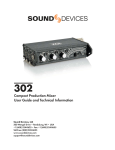
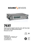
Block Diagram - Inputs and Outputs
www.sounddevices.com/442
page 16
www.sounddevices.com/442
5
10
9
1
4
2
3
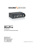
Mates with Hirose #RM15TD-10P
connector.
User Guide and Technical Information
1. . . . . .L (+) output
2. . . . . .L (–) output
3. . . . . .R (+) output
4. . . . . .R (–) output
5. . . . . .R (+) return A
6. . . . . .n/c
7. . . . . .L (+) return A
8. . . . . .n/c
9. . . . . .ground
10. . . . .ground
6
7
8
Multi-Pin Camera
Pin Outs
442
SOUND DEVICES, LLC
Block Diagram - Monitoring
page 17
442
User Guide and Technical Information
SOUND DEVICES, LLC
Approvals
FCC Statement
This device has been tested and found to comply with the limits for a class B digital device, pursuant to part 15 of the FCC
rules. These limits are designed to provide reasonable protection against harmful interference in a residential installation. This
equipment generates, uses, and can radiate radio frequency energy and, if not installed and used in accordance with the
instructions, may cause harmful interference to radio communications. However, there is no guarantee that interference will
not occur in a particular installation.
CE Conformity Statement
Declaration of Conformity
According to ISO/IEC Guide 22
Manufacturer's Name:
Sound Devices, LLC
Manufacturer's Address:
Sound Devices, LLC
300 Wengel Drive
Reedsburg, WI 53959
declares that the product:
442 Field Mixer
is in conformity with:
Document No.
EN55103-1 (1997)
EN55103-2 (1997)
EN55022 (1995)/
CISPR 22 (1997)
EN61000-4-2 (1995)/
IEC1000-4-2 (1995)
EN61000-4-3 (1995)/
IEC1000-4-3 (1995)
EN61000-4-4 (1995)/
IEC1000-4-4 (1995)
EN61000-4-6 (1996)/
IEC1000-4-6 (1996)
Tested by:
L. S. Compliance, Inc.
December 16, 2001
USA
Description
Emissions standard for product family audio devices for professional use
Immunity standard for product family audio devices for professional use
Radiated and Conducted emissions, Class B
ESD - 6kV contact, 8kV air-discharge
Radiated RF Immunity, 10 V/m, 80% 1 kHz amplitude
modulation
EFT/Burst, I/O lines, +/- .25 kV to +/- 1.0 kV
Conducted RF Immunity, 10 V, 80% 1 kHz amplitude modulation
Cedarburg, Wisconsin
Matthew Anderson
Director of Engineering
Warranty
Sound Devices, LLC warrants the 442 Field Mixer against defects in materials and workmanship for a period of ONE (1) year
from date of original retail purchase. This is a non-transferable warranty that extends only to the original purchaser. Sound
Devices, LLC will repair or replace the product at its discretion at no charge. Warranty claims due to severe service conditions will be addressed on an individual basis. THE WARRANTY AND REMEDIES SET FORTH ABOVE ARE EXCLUSIVE.
SOUND DEVICES, LLC DISCLAIMS ALL OTHER WARRANTIES, EXPRESS OR IMPLIED, INCLUDING WARRANTIES OF
MERCHANTABILITY AND FITNESS FOR A PARTICULAR PURPOSE. SOUND DEVICES, LLC IS NOT RESPONSIBLE
FOR SPECIAL, INCIDENTAL, OR CONSEQUENTIAL DAMAGES ARISING FROM ANY BREACH OF WARRANTY OR
UNDER ANY OTHER LEGAL THEORY. Because some jurisdictions do not permit the exclusion or limitations set forth above,
they may not apply in all cases.
For all service, including warranty repair, please send the 442, along with proof of purchase date to:
Sound Devices, LLC
Service Repair
300 Wengel Drive
Reedsburg, WI 53959 USA
www.sounddevices.com/442
page 18
442
User Guide and Technical Information
SOUND DEVICES, LLC
Appendix A - 442 Nordic Information
The 442 Nordic (442N) is identical to the 442 except for its Nordic scale PPM meter.
Setup Menus
The Setup Menus vary slightly between the 442 and the 442N. To set the limiter
threshold level an additional LED is illuminated for calculation. To find the limiter
threshold value, consult the chart below.
Example: Change the Limiter Threshold from the factory default of +20 dBu to
+14 dBu.
1. Enter the Setup Menu by holding down the PK/VU button while powering the
mixer.
2. The Limiter Threshold setup is the first position (see Setup Menu).
3. To move among parameter values,
press the brightness LED and battery check LED until the left meter
illuminates “10” and the right meter
illuminates “4”.
4. Press the PK/VU button multiple
times until the meters perform their
scrolling dance. This sets the
parameter into memory.
Level Left (top) Right (botMeter tom) Meter
(in dBu)
+20
20
0
+19
10
10+8
+18
10
8
+17
10
8+6
+16
10
6
+15
10
6+4
+14
10
4
+13
10
4+2
+12
10
2
+11
10
2+0
+10
10
0
+9
10+8
0
+8
8
0
+7
8+6
0
+6
6
0
+5
6+4
0
+4
4
0
Appendix B - Accessory Products
Sound Devices offers several accessories to add value to the 442. These are available from any authorized
Sound Devices Reseller or direct from Sound Devices.
CS-442 . . . .Carry case designed exclusively for Sound Devices 442 Field Mixer. Includes a dedicated pouch for
an NP-type battery and leather shoulder strap. Accepts RM-series accessories and AH-2 harness
(not included).
XL-1 . . . . . .TA3-F to TA3-F link cable for 442 to 442 linking; 6-inch.
XL-2 . . . . . .TA3-F to XLR cable; 15-inch; connects balanced TA3 to XLR inputs; package of two cables.
XL-3 . . . . . .3.5 mm to TA3-F link cable for MixPre/MP-2 Tape Output to 442 Mix In; 12-inch.
XL-4 . . . . . .Bag of four (4) TA3-F-type connectors.
XL-10 . . . . .Hirose 10-pin to two-XLR (balanced L/R) and 3.5 mm plug (442 Stereo Return A) breakout cable;
includes in-line 20-foot extension cable.
XL-H . . . . . .Bare Hirose connector, (Hirose p/n HR10-7P-4P) to mate with locking 4-pin DC power jack.
XL-NP . . . .NP-type battery cup with 12-inch cable with Switchcraft locking DC jack at equipment end. For use
with HX-3, MixPre (s/n <0506...), MM-1, MP-2, and 442 (s/n <0303...).
XL-NPH . . .NP-type battery cup with 12-inch cable with Hirose 4-pin locking power jack at equipment end. For
use with 442N, 442 (s/n >0303...), and MixPre (s/n >0506...).
www.sounddevices.com/442
page 19
442
User Guide and Technical Information
SOUND DEVICES, LLC
Appendix C - Setup Menu (firmware v 5)
The chart below shows the available setups for the 442 and 442N. The flashing left (top) meter LED indicates
the setup selected. The right meter LED indicates the available values, read from left to right.
L Meter
Position
442 (442N)
Values
Setup
Description
bold is factory default
(indicated meter value on R meter of 442)
-30 (-30)
Output Limiter Threshold
Adjustment
Sets the output limiter threshold in dBu
1 dB increments from +4 dBu to +20 dBu
at Line Level output
-20 (-24)
Input Limiter Defeat
Allows the input limiters to remain OFF when the LIM
switch is activated
OFF (-30), ON (-20)
-14 (-22)
Balanced TA3 Output
Level
Selects the nominal output level of the active-balanced TA3
Line-Level (-30), Mic-Level (-20)
outputs
-12 (-20)
Direct Output Level
Selects the nominal output level of the active-balanced TA3
Line-Level (-30), Mic-Level (-20)
channel direct outputs
-10 (-18)
Tone Oscillator Frequency Selects the ƒ of the sine wave setup tone
1000 (-30), 400 (-20), 100 (-14) Hz
-8 (-16)
Tone Oscillator Level
Selects the output level of the tone oscillator in dBu
OFF (-30), -20 dBu (-20), -10 dBu (-10), 1
dB increments to +8 dBu, 0 dBu =
default.
-6 (-14)
Tone @ Direct Output
Selects whether tone is present on the Direct Outputs
ON (-30), OFF (-20)
-4 (-12)
Slate Mic Toggle
Selects whether slate mic is activated when slate toggle
switch is activated
ON (-30), ON with 1 second of 400 Hz
tone preceding (-20),OFF (-14).
-2 (-10)
Comm Mic Function
Allows return A|B toggle to be defeated and be reassigned
to send slate mic signal to right TA3 output when toggled
OFF (-30), ON (-20)
0 (-8)
PFL Level to Meter
Selects whether PFL level is indicated on the output meter
ON (-30), OFF (-20)
2 (-6)
Monitor In Metering
Selects indication of monitor in signal level on the output
meter (post monitor gain control) when the monitor toggle is OFF (-30), ON (-20)
activated
4 (-4)
VU Reference Level
Selects 0 VU to dBu reference
Split-Ear Monitor A
Changes monitoring to hear program audio in one ear and
monitor A in the other ear. Return A is summed and
appears in R (right) headphone and L program appears in L OFF (-30), ON (-20)
(left) headphone. Is only active when Return toggle switch
is activated.
Split-Ear Monitor B
Changes monitoring to hear program audio in one ear and
monitor B in the other ear. Return B is summed and
appears in L (left) headphone and R program appears in R OFF (-30), ON (-20)
(right) headphone. Is only active when Return toggle switch
is activated.
10 (2)
Return Toggle Assignment
Allows the three-position monitor toggle to be assigned
depending on preferred monitor connection used
A|OFF|B (-30), B|OFF|A (-20), A|OFF|A (14), B|OFF|B (-12)
12 (4)
Headphone Attenuation
with Tone
Reduces the headphone level by 20 dB when the tone
oscillator is activated
ON (-30), OFF (-20)
14 (6)
External Battery Voltage
Reference
Selects the Voltage range of the battery check function with
1 (-30), 2 (-20), 3 (-14), 4 (-12), 5 (-10),
external power. Also adjusts the flashing power LED voltage
6 (-8) - see POWERING for index
under external power.
6 (-2)
8 (0)
0 dBu (-30), +4 dBu (-20), +8 dBu (-14)
16 (8)
Meter Ballistics Select
Selects the meter ballistics options available at the meter
selection button.
PPM|VU|VU-PPMHold|VU-PPM (-30),
PPM|VU-PPMHold|VU-PPM (-20),
VU|VU-PPMHold|VU-PPM (-14),
PPM|VU-PPM (-12),
VU-PPM|VU-PPMHold (-10)
18 (10)
Default Restore
Restores setup menu to the stored user default or to the
factory default settings
OFF (-30) , User Default (-20), Factory
Default (-14)
www.sounddevices.com/442
page 20
442
User Guide and Technical Information
SOUND DEVICES, LLC
Appendix D - Setup Menu (firmware v 3 & 4)
The chart below shows the available setups for the 442 and 442N. The flashing left (top) meter LED indicates
the setup selected. The right meter LED indicates the available values, read from left to right.
L Meter
Position
442 (442N)
Values
Setup
Description
bold is factory default
(indicated meter value on R meter of 442)
-30 (-30)
Output Limiter Threshold
Adjustment
Sets the output limiter threshold in dBu
1 dB increments from +4 dBu to +20 dBu
at Line Level output
-20 (-24)
Input Limiter Defeat
Allows the input limiters to remain OFF when the LIM
switch is activated
OFF (-30), ON (-20)
-14 (-22)
Balanced TA3 Output
Level
Selects the nominal output level of the active-balanced TA3
Line-Level (-30), Mic-Level (-20)
outputs
-12 (-20)
Direct Output Level
Selects the nominal output level of the active-balanced TA3
Line-Level (-30), Mic-Level (-20)
channel direct outputs
-10 (-18)
Tone Oscillator Frequency Selects the frequency of the sine wave setup tone
1000 (-30), 400 (-20), 100 (-14) Hz
-8 (-16)
Tone Oscillator Level
Selects the output level of the tone oscillator in dBu
OFF (-30), -20 dBu (-20), -10 dBu (-10), 1
dB increments to +8 dBu, 0 dBu =
default.
-6 (-14)
Tone @ Direct Output
Selects whether tone is present on the Direct Outputs
ON (-30), OFF (-20)
-4 (-12)
Slate Mic Toggle
Selects whether slate mic is activated when slate toggle
switch is activated
ON (-30), ON with 1 second of 400 Hz
tone preceding (-20),OFF (-14). Note:
tone not an option on firmware v3.
-2 (-10)
Comm Mic Function
Allows return A|B toggle to be defeated and be reassigned
to send slate mic signal to right TA3 output when toggled
OFF (-30), ON (-20)
0 (-8)
PFL Level to Meter
Selects whether PFL level is indicated on the output meter
ON (-30), ON (-20)
2 (-6)
Monitor In Metering
Selects indication of monitor in signal level on the output
meter (post monitor gain control) when the monitor toggle is OFF (-30), ON (-20)
activated
4 (-4)
VU Reference Level
Selects 0 VU to dBu reference
Split-Ear Monitor A
Changes monitoring to hear program audio in one ear and
monitor A in the other ear. Return A is summed and
appears in R (right) headphone and L program appears in L OFF (-30), ON (-20)
(left) headphone. Is only active when Return toggle switch
is activated.
Split-Ear Monitor B
Changes monitoring to hear program audio in one ear and
monitor B in the other ear. Return B is summed and
appears in L (left) headphone and R program appears in R OFF (-30), ON (-20)
(right) headphone. Is only active when Return toggle switch
is activated.
10 (2)
Return Toggle Assignment
Allows the three-position monitor toggle to be assigned
depending on preferred monitor connection used
A|OFF|B (-30), B|OFF|A (-20), A|OFF|A (14), B|OFF|B (-12)
12 (4)
Headphone Attenuation
with Tone
Reduces the headphone level by 20 dB when the tone
oscillator is activated
ON (-30), OFF (-20)
14 (6)
External Battery Voltage
Reference
Selects the Voltage range of the battery check function with
1 (-30), 2 (-20), 3 (-14), 4 (-12), 5 (-10),
external power. Also adjusts the flashing power LED voltage
6 (-8) - see POWERING for index
under external power.
16 (8)
Meter Ballistics Select
Selects the meter ballistics options available at the meter
selection button.
PPM|VU|VU-PPMHold|VU-PPM (-30),
PPM|VU-PPMHold|VU-PPM (-20),
VU|VU-PPMHold|VU-PPM (-14),
PPM|VU-PPM (-12),
VU-PPM|VU-PPMHold (-10)
18 (10)
Factory Default Restore
Enables the factory defaults to be reset
OFF (-30) , Reset (-20)
6 (-2)
8 (0)
www.sounddevices.com/442
0 dBu (-30), +4 dBu (-20), +8 dBu (-14)
page 21
442
User Guide and Technical Information
SOUND DEVICES, LLC
Appendix E - Setup Menu (firmware v 2, 442 only)
The chart below is provided for users with the original production 442 firmware. Determine the firmware revision
by viewing the meters when the unit is powered up. The left meter indicates the firmware version. The meters
“dance” then an LED is lit. If the second LED from the left is lit, the unit has firmware version 2.
L Meter
Position
442
Values
Setup
Description
bold is factory default
(indicated meter value on R meter)
-30
Output Limiter Threshold
Adjustment
Sets the output limiter threshold in dBu
1 dB increments from +4 dBu to +20 dBu
at Line Level output
-20
Input Limiter Defeat
Allows the input limiters to remain OFF when the LIM
switch is activated
OFF (-30), ON (-20)
-14
Balanced TA3 Output
Level
Selects the nominal output level of the active-balanced TA3
Line-Level (-30), Aux-Level (-20)
outputs
-12
Direct Output Level
Selects the nominal output level of the active-balanced TA3
Line-Level (-30), Aux-Level (-20)
channel direct outputs
-10
Tone Oscillator Frequency Selects the frequency of the sine wave setup tone
100 (-30), 400 (-20), 1000 (-14) Hz
-8
Tone Oscillator Level
Selects the output level of the tone oscillator in dBu
-20 dBu (-30), -10 dBu (-20), -8 dBu (-14),
0 dBu (-12), +4 dBu (-10), +8 dBu (-8),
OFF (-6)
-6
Tone @ Direct Output
Selects whether tone is present on the Direct Outputs
OFF (-30), ON (-20)
-4
Slate Mic Toggle
Selects whether slate mic is activated when slate toggle
switch is activated
ON (-30), OFF (-20)
-2
Comm Mic Function
Allows return A|B toggle to be defeated and be reassigned
to send slate mic signal to right TA3 output when toggled
OFF (-30), ON (-20)
0
PFL Level to Meter
Selects whether PFL level is indicated on the output meter
OFF (-30), ON (-20)
2
Monitor In Metering
Selects indication of monitor in signal level on the output
meter (post monitor gain control) when the monitor toggle is OFF (-30), ON (-20)
activated
4
VU Reference Level
Selects 0 VU to dBu reference
Split-Ear Monitor A
Changes monitoring to hear program audio in one ear and
monitor A in the other ear. Return A is summed and
appears in R (right) headphone and L program appears in L OFF (-30), ON (-20)
(left) headphone. Is only active when Return toggle switch
is activated.
Split-Ear Monitor B
Changes monitoring to hear program audio in one ear and
monitor B in the other ear. Return B is summed and
appears in L (left) headphone and R program appears in R OFF (-30), ON (-20)
(right) headphone. Is only active when Return toggle switch
is activated.
10
Return Toggle Assignment
Allows the three-position monitor toggle to be assigned
depending on preferred monitor connection used
A|OFF|B (-30), B|OFF|A (-20),
A|OFF|A (-14), B|OFF|B (-12)
12
Headphone Attenuation
with Tone
Reduces the headphone level by 20 dB when the tone
oscillator is activated
OFF (-30), ON (-20)
14
External Battery Voltage
Reference
Selects the Voltage range of the battery check function with
1 (-30), 2 (-20), 3 (-14), 4 (-12), 5 (-10),
external power. Also adjusts the flashing power LED voltage
6 (-8) - see POWERING for index
under external power.
16
Factory Default Restore
Returns the 442 to the factory defaults settings
6
8
www.sounddevices.com/442
0 dBu (-30), +4 dBu (-20), +8 dBu (-14)
OFF (-30) , Reset (-20)
page 22
442
User Guide and Technical Information
SOUND DEVICES, LLC
Notes
www.sounddevices.com/442
page 23
®
www.sounddevices.com
firmware version 5