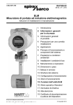
1
Operating Instructions for Transmitter for magnetic-inductive Flowmeter Model: UMF2 INTRODUCTION ............................................................................................................ 8 I. Shipping and storage; product inspection ............................................................................................. 8 II. Warranty ............................................................................................................................................ 8 III. Application domain the operating manual ......................................................................................... 8 IV. Measures to be taken before sending your device to the manufacturer for repair............................ 8 V. Supplementary operating instructions regarding the HART£ interface ............................................ 8 VI. Operating manual of explosion-proof flowmeters.............................................................................. 8 1. STEPS PRIOR TO OPERATION........................................................................... 9 1.1 Installation and servicing ................................................................................................................. 10 1.2 Safety advisory for the user ............................................................................................................. 10 1.3 Hazard warnings.............................................................................................................................. 10 1.3.1 Danger ...................................................................................................................................... 10 1.3.2 Warning .................................................................................................................................... 10 1.3.3 Caution ..................................................................................................................................... 11 1.3.4 Note .......................................................................................................................................... 11 1.4 Proper use of the device.................................................................................................................. 11 1.5 Returning your flowmeter for servicing or calibration ...................................................................... 11 1.6 Replacement of the transmitter electronics ..................................................................................... 12 2. IDENTIFICATION ................................................................................................ 13 3. COMMISSIONING ............................................................................................... 14 3.1 Installation of magnetic-inductive flowmeters .................................................................................. 14 3.2 Potentials ......................................................................................................................................... 14 3.3 Cathodic protective units..................................................................................................................... 14 3.4 Zero point calibration ....................................................................................................................... 15 3.5 Startup conditions ............................................................................................................................ 15 3.6 Commisioning the PIT and PITY flow velocity sensors ................................................................... 15 4. APPLICATION DOMAIN OF UMF2 TRANSMITTER........................................... 16 Page 2 of 82 OPERATING MANUAL UMF2 5. UMF2 TRANSMITTER: MODE OF OPERATION AND CONFIGURATION .........17 5.1 Measuring principle ......................................................................................................................... 17 5.2 System design ................................................................................................................................. 18 5.2.1 Basic version UMF2 ................................................................................................................. 18 5.2.2 Optional equipment .................................................................................................................. 18 5.2.2.1 HART-Interface ................................................................................................................. 18 5.2.2.2 Control unit BE3 ................................................................................................................ 19 5.2.2.3 Empty pipe detection......................................................................................................... 19 5.2.3 Data memory chip DSM ........................................................................................................... 20 5.2.4 Safety of operation ................................................................................................................... 20 6. INPUT...................................................................................................................21 6.1 Measured variable ........................................................................................................................... 21 6.2 Measuring range.............................................................................................................................. 21 6.3 Operating the PIT and PITY flow velocity sensors with the UMF2.................................................. 21 7. OUTPUT...............................................................................................................22 7.1 Output signal.................................................................................................................................... 22 7.2 Failure signal ................................................................................................................................... 23 7.3 Load of the current output ............................................................................................................... 23 7.4 Damping .......................................................................................................................................... 23 7.5 Low flow cut-off................................................................................................................................ 23 8. UMF2 PERFORMANCE CHARACTERISTICS ....................................................24 8.1 Reference conditions....................................................................................................................... 24 8.2 Measuring tolerance ........................................................................................................................ 24 8.3 Repeatability .................................................................................................................................... 24 8.4 Influence of ambient temperature.................................................................................................... 24 9. UMF2 OPERATING CONDITIONS ......................................................................24 9.1 Installation conditions ...................................................................................................................... 24 9.1.1 Compact version ...................................................................................................................... 24 9.1.2 Separate version ...................................................................................................................... 24 9.2 Environmental conditions ................................................................................................................ 26 9.2.1 Ambient temperature................................................................................................................ 26 9.2.2 Ambient temperature range...................................................................................................... 26 9.2.3 Storage temperature ................................................................................................................ 26 OPERATING MANUAL UMF2 Page 3 of 82 9.2.4 Degree of protection ................................................................................................................. 26 9.3 Process conditions........................................................................................................................... 27 9.3.1 Fluid temperature ..................................................................................................................... 27 9.3.2 State of aggregation ................................................................................................................. 27 9.3.3 Viscosity.................................................................................................................................... 27 9.3.4 Fluid temperature limit .............................................................................................................. 27 9.3.5 Flow rate limit ........................................................................................................................... 27 9.3.6 Pressure loss............................................................................................................................ 27 9.3.7 Empty pipe detection ................................................................................................................ 27 10. CONSTRUCTION DEETAILS.............................................................................. 28 10.1 Type of construction / dimensions ............................................................................................... 28 10.2 Weight .......................................................................................................................................... 29 10.3 Material......................................................................................................................................... 29 10.4 Process connection...................................................................................................................... 29 10.5 Electrical connection .................................................................................................................... 29 10.5.1 UMF2 process terminals .......................................................................................................... 29 10.5.2 UMF2 sensor terminals ............................................................................................................ 30 10.6 Cable specification ....................................................................................................................... 30 10.6.1 Wiring diagrams........................................................................................................................ 31 10.6.1.1 Wiring diagram compact version....................................................................................... 31 10.6.1.2 Wiring diagramm for the separate version ........................................................................ 32 10.6.2 HART® connection .................................................................................................................... 33 11. DISPLAY AND OPERATOR INTERFACE BASIC VERSION .............................. 34 11.1 Zero point adjust .......................................................................................................................... 34 11.2 LED display .................................................................................................................................. 35 12. MAINTENANCE AND REPAIR ............................................................................ 36 12.1 Mains fuse .................................................................................................................................... 36 12.2 Replacement of terminal board.................................................................................................... 36 12.3 Exchange of transmitter electronic............................................................................................... 36 13. UMF2 CONTROL UNIT BE3 (OPTION) .............................................................. 37 13.1 Introduction .................................................................................................................................. 37 13.2 Display.......................................................................................................................................... 37 13.3 Operating modes.......................................................................................................................... 38 Page 4 of 82 OPERATING MANUAL UMF2 13.4 Operation ..................................................................................................................................... 38 13.4.1 Operation interface................................................................................................................... 38 13.4.2 The keys and their functions .................................................................................................... 39 13.4.3 Functional classes, functions and parameters......................................................................... 40 13.4.3.1 Selection window / make a selection ................................................................................ 40 13.4.3.2 Input window / modify a value ........................................................................................... 41 13.4.3.3 Passwords......................................................................................................................... 41 14. UMF2 TRANSMITTER FUNCTIONS....................................................................42 14.1 MEASURED VALUES functional class........................................................................................ 43 14.1.1 Volume flow rate....................................................................................................................... 44 14.1.2 Forward flow counter 1............................................................................................................. 44 14.1.3 Forward flow counter 2............................................................................................................. 44 14.1.4 Reverse flow counter................................................................................................................ 44 14.1.5 Flow velocity ............................................................................................................................. 45 14.1.6 Relative flow rate ...................................................................................................................... 45 14.1.7 QV + Forward flow counter ...................................................................................................... 46 14.1.8 QV + Forward flow counter 2 ................................................................................................... 46 14.1.9 QV + flow velocity..................................................................................................................... 46 14.1.10 Display mode during startup................................................................................................. 47 14.1.11 Raw values ........................................................................................................................... 47 14.2 PASSWORD functional class ...................................................................................................... 48 14.2.1 Customer-password ................................................................................................................. 48 14.2.2 Change customer password .................................................................................................... 49 14.2.3 Service password ..................................................................................................................... 49 14.3 Counter functional class............................................................................................................... 50 14.3.1 Unit of counters ........................................................................................................................ 51 14.3.2 Reset counter ........................................................................................................................... 51 14.4 MEASUREMENT PROCESSING functional class ...................................................................... 52 14.4.1 Damping ................................................................................................................................... 53 14.4.2 Low flow cut-off ........................................................................................................................ 53 14.4.3 Low flow cut-off hysteresis ....................................................................................................... 53 14.4.4 Zero point calibration................................................................................................................ 54 14.5 Flow functional class.................................................................................................................... 55 14.5.1 Volume flow QV unit................................................................................................................. 56 14.5.2 Volume flow lower-range value ................................................................................................ 56 14.5.3 Volume flow upper-range value ............................................................................................... 56 14.5.4 Volume flow limit MIN............................................................................................................... 57 14.5.5 Volume flow limit MAX.............................................................................................................. 57 14.5.6 QV limit hysteresis.................................................................................................................... 57 14.5.7 Density...................................................................................................................................... 58 14.5.8 Volume flow LSL (information field) ......................................................................................... 58 14.5.9 Volume flow USL (information field)......................................................................................... 58 14.6 PULSE OUTPUT functional class................................................................................................ 59 14.6.1 Pulse or frequency output ........................................................................................................ 60 14.6.2 Pulse output unit....................................................................................................................... 60 14.6.3 Pulse value ............................................................................................................................... 61 14.6.4 Pulse width ............................................................................................................................... 61 14.7 STATUS OUTPUT functional class ............................................................................................. 62 OPERATING MANUAL UMF2 Page 5 of 82 14.7.1 14.7.2 Status output active state ......................................................................................................... 62 Status output assignment ......................................................................................................... 63 14.8 CURRENT OUTPUT functional class .......................................................................................... 64 14.8.1 Current output 0/4 - 20 mA ....................................................................................................... 64 14.8.2 Current output alarm................................................................................................................. 65 14.9 SIMULATION functional class ..................................................................................................... 66 14.9.1 Simulation on / off..................................................................................................................... 67 14.9.2 Simulation direct / preset value Q ............................................................................................ 67 14.9.3 Simulation measured flow Q .................................................................................................... 67 14.9.4 Direct simulation of outputs ...................................................................................................... 68 14.9.4.1 Status output simulation .................................................................................................... 68 14.9.4.2 Pulse output simulation ..................................................................................................... 68 14.9.4.3 Current output simulation .................................................................................................. 68 14.10 SELF-TEST fuctional class .......................................................................................................... 69 14.10.1 Self-test test on / off .............................................................................................................. 70 14.10.2 Self-test period (STP) ........................................................................................................... 70 14.10.3 Reference calibration on / off................................................................................................ 70 14.10.4 Reference calibration period (GAP)...................................................................................... 71 14.10.5 Empty pipe detection on / off ................................................................................................ 71 14.10.6 Empty pipe detection period ................................................................................................. 71 14.11 SETTINGS SENSOR + UMF2 functional class ........................................................................... 72 14.11.1 Sensor constant C ................................................................................................................ 73 14.11.2 Sensor type........................................................................................................................... 73 14.11.3 Inside diameter ..................................................................................................................... 73 14.11.4 Language .............................................................................................................................. 74 14.11.5 Excitation frequency.............................................................................................................. 74 14.11.6 Mains frequency.................................................................................................................... 74 14.11.7 Flow direction........................................................................................................................ 75 14.11.8 Software version (information field) ...................................................................................... 75 14.11.9 Serial number (information field)........................................................................................... 76 14.11.10 Show system errors .......................................................................................................... 76 14.11.11 Reset system error ............................................................................................................ 76 15. UMF2 TRANSMITTER ERROR MESSAGES...................................................... 77 15.1 Basic Version ............................................................................................................................... 77 15.2 Enhanced version with LC-Display .............................................................................................. 77 15.3 Standard operating mode ............................................................................................................ 77 15.4 List of error messages.................................................................................................................. 78 15.4.1 Display of self-test errors.......................................................................................................... 78 15.4.2 Display of system error............................................................................................................. 79 15.4.3 Reset system error ................................................................................................................... 79 16. CERTIFICATES AND APPROVALS.................................................................... 80 17. STANDARDS AND AUTHORIZATIONS.............................................................. 80 Page 6 of 82 OPERATING MANUAL UMF2 17.1 General standards and directives ................................................................................................ 80 17.2 Electromagnetic compatibility ...................................................................................................... 80 18. DECONTAMINATION CERTIFICATE FOR DEVICE CLEANING ........................81 OPERATING MANUAL UMF2 Page 7 of 82 Introduction I. Shipping and storage; product inspection Shipping and storage The device is to be safeguarded against dampness, dirt, impact and damage. Product inspection Upon receipt of the product, check the contents of the box and the product particulars against the information on the delivery slip and order form so as to ensure that all ordered components have been supplied. Notify us of any shipping damage immediately upon receipt of the product. Any damage claim received at a later time will not be honored. II. Warranty Your flowmeter was manufactured in accordance with the highest quality standards and was thoroughly tested prior to shipment. However, in the event any problem arises with your device, we will be happy to resolve the problem for you as quickly as possible under the terms of the warranty which can be found in the terms and conditions of delivery. Your warranty will only be honored if the device was installed and operated in accordance with the instructions for your device. Any mounting, commissioning and/or maintenance work is to be carried out by qualified and authorized technicians only. III. Application domain the operating manual The present manual applies to magnetic-inductive flowmeters series PIT, PITY and DMH that are operated in conjunction with the UMF2 transmitter. IV. Measures to be taken before sending your device to the manufacturer for repair It is important that you do the following before shipping your flowmeter to Kobold Messring GmbH for repair: x Enclose a description of the problem with your device. Describe in as much detail as possible the application and the physical and chemical properties of the fluid. x Remove any residues from the device and be sure to clean the seal grooves and recesses thoroughly. This is particularly important if the fluid is corrosive, toxic, carcinogenic, radioactive or otherwise hazardous. The operator is liable for any substance removal or personal damage costs arising from inadequate cleaning of a device that is sent for repair. V. Supplementary operating instructions regarding the HART£ interface For information regarding operation of the transmitter using the HART£ hand-held terminal, see “Operation of the UMF2 transmitter using the HART£ hand-held terminal.” VI. Operating manual of explosion-proof flowmeters For installation of the sensor and transmitter within hazardous areas the transmitter UMF2 has no approval. Page 8 of 82 OPERATING MANUAL UMF2 1. Steps prior to operation It is essential that you read these operating instructions before installing and operating the device. The device is to be installed and serviced by a qualified technician only. The UMF2 transmitter is to be used exclusively to measure mass and volume flow, as well as liquid and gas density and temperature, in conjunction with a Kobold Messring PIT, PITY or DMH sensor. Downloading of the present document from our web site www.kobold.com and printing out this document is allowed only for purposes of using our mass flowmeters. All rights reserved. No instructions, wiring diagrams, and/or supplied software, or any portion thereof, may be produced, stored, in a retrieval system or transmitted by any means, electronic, mechanical, photocopying or otherwise, without the prior written permission of Kobold Messring GmbH. Although the materials in the present document were prepared with extreme care, errors cannot be ruled out. Hence, neither the company, the programmer nor the author can be held legally or otherwise responsible for any erroneous information and/or any loss or damage arising from the use of the information enclosed. Kobold Messring GmbH extends no express or implied warranty in regard to the applicability of the present document for any purpose other than that described. We reserve the right to change the technical data in this manual in the light of any technical progress that might be made. For updates regarding this product, visit our website at www.kobold.com, where you will also find contact information for the Kobold Messring GmbH distributor nearest you. For information regarding our own sales operations, contact us at [email protected]. OPERATING MANUAL UMF2 Page 9 of 82 1.1 Installation and servicing The devices described in this manual are to be installed and serviced only by qualified technical personnel such as a qualified Kobold Messring electronics engineer or service technician. Warning Before servicing the device, it must be completely switched off, and disconnected from all peripheral devices. The technician must also check to ensure that the device is completely off-circuit. Only original replacement parts are to be used. Kobold Messring GmbH accepts no liability for any loss or damage of any kind arising from improper operation of any product, improper handling or use of any replacement part, or from external electrical or mechanical effects, overvoltage or lightning. Any such improper operation, use or handling shall automatically invalidate the warranty for the product concerned. In the event a problem arises with your device, please contact Kobold Messring GmbH. Contact our customer service department if your device needs repair or if you need assistance in diagnosing a problem with your device 1.2 Safety advisory for the user The present document contains the information that you need in order to operate the product described herein properly. The document is intended for use by qualified personnel. This means personnel who are qualified to operate the device described herein safely, including electronics engineers, electrical engineers, or service technicians who are conversant with the safety regulations pertaining to the use of electrical and automated technical devices and with the applicable laws and regulations in their own country. Such personnel must be authorized by the facility operator to install, commission and service the product described herein, and are to read and understand the contents of the present operating instructions before working with the device. 1.3 Hazard warnings The purpose of the hazard warnings listed below is to ensure that device operators and maintenance personnel are not injured and that the flowmeter and any devices connected to it are not damaged. The safety advisories and hazard warnings in the present document that aim to avoid placing operators and maintenance personnel at risk and to avoid material damage are prioritized using the terms listed below, which are defined as follows in regard to these instructions herein and the advisories pertaining to the device itself. 1.3.1 Danger means that failure to take the prescribed precautions will result in death, severe bodily injury, or substantial material damage. 1.3.2 Warning means that failure to take the prescribed precautions could result in death, severe bodily injury, or substantial material damage. Page 10 of 82 OPERATING MANUAL UMF2 1.3.3 Caution means that the accompanying text contains important information about the product, handling the product or about a section of the documentation that is of particular importance. 1.3.4 Note means that the accompanying text contains important information about the product, handling the product or about a section of the documentation that is of particular importance. 1.4 Proper use of the device Warning The operator is responsible for ensuring that the material used in the sensor and housing is suitable and that such material meets the requirements for the fluid being used and the ambient site conditions. The manufacturer accepts no responsibility in regard to such material and housing. Warning In order for the device to perform correctly and safely, it must be shipped, stored, set up, mounted operated and maintained properly. 1.5 Returning your flowmeter for servicing or calibration Before sending your flowmeter back to us for servicing or calibration, make sure it is completely clean. Any residues of substances that could be hazardous to the environment or human health are to be removed from all crevices, recesses, gaskets, and cavities of the housing before the device is shipped. Warning The operator is liable for any loss or damage of any kind, including personal injury, decontamination measures, removal operations and the like that are attributable to inadequate cleaning of the device. Any device sent in for servicing is to be accompanied by a certificate as specified in Section 18 Decontamination certificate for device cleaning ! The device is to be accompanied by a document describing the problem with the device. Please include in this document the name of a contact person that our technical service department can get in touch with so that we can repair your device as expeditiously as possible and therefore minimize the cost of repairing it. OPERATING MANUAL UMF2 Page 11 of 82 1.6 Replacement of the transmitter electronics Before replacing the transmitter electronics, read the safety instructions in Section 1.1 Installation and servicing on page 10. Warning Make sure that you abide by the applicable standards and regulations pertaining to electrical devices, device installation and process technology when replacing the transmitter electronics. The highly integrated electronic components in the device carry the risk of ESD hazards and are only protected when installed in the device pursuant to EMC standards. The exchange of electronic components or board is described in details in chapter 12 Maintenance and repair starting at page 36. Caution The complete insert is to be replaced with all of its printed boards (except for the memory chip (DSM)). This is particularly important for the explosion-proof transmitter. The specified precision and interchangeability of the electronics are only guaranteed if the complete insert is replaced. Page 12 of 82 OPERATING MANUAL UMF2 2. Identification Manufacturer Kobold Messring GmbH Nordring 22-24 D - 65719 Hofheim/Ts. Phone: +49 (0) 6192 299-0 Fax: +49 (0) 6192 299-23398 Internet: www.kobold.com e-mail : [email protected] Product type Product name Transmitter for magnetic-inductive flowmeters Transmitter Type UMF2, suitable for PIT, PITY and DMH magnetic-inductive flowmeters Version no s5gbm_umf2_k01_0809 OPERATING MANUAL UMF2 Page 13 of 82 3. Commissioning 3.1 Installation of magnetic-inductive flowmeters At the installation of the magnetic-inductive flow sensor the instructions and notes of the assembly instructions and operating manuals have to be followed. Also, abserve the regulations of grounding, potential equalization and company-internal grounding guidelines. 3.2 Potentials All outputs are electrically isolated from the auxiliary power, the sensor circuit and from each other. The housing and the interference suppression filters of the power supply are connected to PE. The electrodes and measuring electronics are related to the potential of the function earth FE of the sensor. FE is not connected to PE, but may be connected with each other in the sensor junction box. If the sensor is grounded by using ground disks (earthing rings), these must in connected with the function earth FE. At a separate assembly of sensor and transmitter the outer screen of the connecting cable is connected to the transmitter housing and has PE potential. The inner screens of the electrode line are connected to FE inside the junction box of the sensor and to the mass (Gnd) of the transmitters electronic. Details of all wirings, terminals and drawing can be found in the chaper 10.5 Electrical connection starting at page 29. 3.3 Cathodic protective units Using a cathodic protective unit to avoid corosion, which put a voltage to the tube wall, it must be connected to terminal FE. The transmitter boards, control panal and internal switches are on the same potential as FE. Warning According to EN 50178:1997 all electrical circuits with „protectiv safety isolation without any protection against contacts must observe the following maximum voltages: x Maximum AC voltage (root mean square value) 25 V x Maximum DC voltage 60 V It is strictly forbidden to connect FE to any higher voltage! Page 14 of 82 OPERATING MANUAL UMF2 3.4 Zero point calibration In order to ensure that precise measurements are obtained, zero point calibration is to be realized the first time the device is put into operation and before any regular operations are carried out. Zero point calibration is to be carried out using a fluid. The zero calibration procedure is as follows: x Install the sensor as described in the manufacturer’s instructions. x Check to ensure that the sensor is completely filled with fluid and that there are no gas bubbles in the flow tubes. x Define the process conditions such as pressure, temperature and density. x Close a potential shut-off device behind the sensor. x Operate the transmitter in accordance with the instructions in chapter 11.1 Zero point adjust on page 34 for the basic version or chapter 14.4.4 Zero point calibration on page 54 for the version with the control panel BE3. x Make sure that sufficient time is allowed for the electronics to warm up. x Allowing fluid to flow through the sensor during the zero calibration procedure will skew the zero point and result in false readings. 3.5 Startup conditions The device is not subject to specific startup conditions. However, pressure surges should be avoided. 3.6 Commisioning the PIT and PITY flow velocity sensors In order to be able to calculate the volume flow when using the sensors of the series PIT and PITY correctly from the measured flow velocity, the installation requirements must be kept regarding position and mounting depth correctly. If from the manufacturer already during the calibration of the measuring instrument does not take place, the settings must be made as specified in chapter 6.3 Operating the PIT and PITY flow velocity sensors with the UMF2 on page 21 to the correct operation! This applies in particular with exchange or when changes in the tubing cross section of existing installations. OPERATING MANUAL UMF2 Page 15 of 82 4. Application domain of UMF2 transmitter The microprocessor controlled UMF2 transmitter (hereinafter referred to as UMF2) for use with PIT, PITY and DMH sensors is a programmable transmitter that processes measurement data and displays and transmits various types of measurement results. The UMF2 is communication enabled and supports optional the HART® protocol. The device can be customized using control unit BE3 (option). Although basic configuration settings such as transmitter calibration are realized at the factory, other settings such as those for measurement data processing, analysis, display and output are user definable. User settings are protected by a user definable password. Settings that are essential for proper operation of the transmitter in conjunction with the sensor (e.g. calibration and initialization values) are accessible only to service technicians via a password that is not provided to customers. Page 16 of 82 OPERATING MANUAL UMF2 5. UMF2 transmitter: mode of operation and configuration 5.1 Measuring principle It was back in 1832 that Faraday suggested utilizing the principle of electrodynamic induction for measuring flow velocities. His experiments in the Thames, though unsuccessful due to superimposed polarization effects, are nonetheless regarded as the first experiment in the field of magnetic-inductive flow measurement. According to Faraday’s law of electromagnetic induction, an electrical field E is produced in a conductive liquid moving through a magnetic field B at a velocity v in accordance with the vector product E = [v x B]. Through a meter tube provided with an insulating lining a liquid flows at velocity v and a flow rate Q, producing a measuring-circuit voltage Um at the two electrodes at right angles to the direction of flow. The size of this measuring-circuit voltage is proportional to the mean flow velocity and the volume flow rate. OPERATING MANUAL UMF2 Page 17 of 82 5.2 System design The meter consists of a sensor e.g. DMH series and a UMF2 transmitter. The device can be used to perform measurements with any liquid, conductive media, providing that the sensor’s material is suitable for the product being used. The UMF transmitter generates the inductive current necessary for the magnetic field and preprocesses the induced voltage at the electrodes. 5.2.1 Basic version UMF2 An analog 0/4...20 mA current output (active), a pulse or frequency output and a status output are standard features of the device. A green LED is an operational readiness indicator, error are indicated by a red light and reverse flow by a yellow light. 5.2.2 5.2.2.1 Optional equipment HART-Interface An analog 0/420 mA output is a standard feature and digital data transmission via HART® protocol as an optional feature of the device. A retrofit by customer is not possible. Page 18 of 82 OPERATING MANUAL UMF2 5.2.2.2 Control unit BE3 Instead of the three light indicators, a LCD display with backlight is an optional feature. The display shows measured values as well as diagnostics. With 6 keypads customers are able to configure comfortable and simple the transmitter without any other tool. 5.2.2.3 Empty pipe detection Transmitters, which are equipped with a control unit BE3, have an on and off switch able empty pipe detection. The operating reliability depends on the conductivity of the liquid medium and the cleanliness of the electrodes. As bigger the conductivity is, as more reliable operates the empty pipe detection. Insulation coatings on the electrodes surface worse the empty pipe detection. OPERATING MANUAL UMF2 Page 19 of 82 6. Input 6.1 Measured variable Mass flow rate, temperature, density and volume flow (calculated from the preceding measured variables). 6.2 Measuring range The measuring range, which varies according to which sensor is used, can be found on the relevant data sheet or rating plate. 6.3 Operating the PIT and PITY flow velocity sensors with the UMF2 The PIT and PITY sensors are calibrated for flow velocity. In order to display the measured value in volume flow units, it must be converted using the flow velocity and the inside diameter of the tube. The following parameters must be set at the UMF2: 1. At the functional level Sensor Settings+UMF2, set the sensor type (PIT or PITY). The dimension of the sensor constants will be automatically set to m/s*mV. 2. Setting of the sensor constants in x.xxx m/s*mV 3. Inside diameter of the tube in xxx mm 4. At the functional class Flow, set the desired unit of volume flow. 5. Using the function Volume Flow Upper-Range Value, set the upper-range value. OPERATING MANUAL UMF2 Page 21 of 82 7. Output 7.1 Output signal All signal outputs: Electrically isolated from each other and from ground (PE). Analog output: 0/4-mA current output, electrically isolated, optional with HART® Volume flow or flow speed (Using the HART®-protocol the current output has to be assigned to volume flow in the mode of 4-20mA) Pulse output: Pulse duration; default value 50 ms, Pulse duration adjustable range is 0,1 ... 2000 ms Mark-to-space ratio is 1:1, if the set pulse duration is not reached. When programming the pulse duration, a plausibility check is carried out. If the selected pulse duration is too long for the set upper range value, an error message will be displayed. fmax = 1 kHz passive via optocoupler U = 24 V Umax = 30 V Imax = 60 mA Pmax = 1,8 W Pulse value: 1 pulse/unit The pulse value can be multiplied by a factor between 0.001 100.0 (decade increments) of the selected pulse unit (e.g. m³) Status output: for: forward and reverse flow, MIN flow rate, MAX flow rate or alarm, passive via optocoupler U = 24 V Umax = 30 V Imax = 60 mA Pmax = 1,8 W Page 22 of 82 OPERATING MANUAL UMF2 7.2 Failure signal A failure in the meter can be indicated via the current output or the status output. The current output ca be set to a failure signal (alarm) of I < 3.8 mA or I > 22 mA. The status output can be configured as make or break contact. 7.3 Load of the current output Standard version: HART£ minimum load 7.4 d > 600 Ohm 250 Ohm Damping Programmable from 0 to 60 seconds 7.5 Low flow cut-off The low-flow cut-off can be set to values between 0 and 20% using the software. The set value refers to the upper range value. If the measured value is lower than the set volume, the flow rate will set to 0.0 (l/h). This results in the analog output being set to 0/4 mA, and the pulse output will stop generating pulses. The configurable hysteresis takes effect only one side while exceeding this limit. OPERATING MANUAL UMF2 Page 23 of 82 8. UMF2 performance characteristics 8.1 Reference conditions In conformity with IEC 770: temperature: 20° C, relative humidity: 65%, air pressure: 101,3 kPa 8.2 Measuring tolerance See characteristic values of the corresponding sensor. 8.3 Repeatability See characteristic values of the corresponding sensor. 8.4 Influence of ambient temperature For the pulse output: For the current output: r 0.05 % per 10 K. r 0.1 % per 10 K. 9. UMF2 operating conditions 9.1 Installation conditions The UMF2 transmitter can be installed directly on the sensor (compact version) observing the operating conditions of the sensor or be mounted separately on the outside (separated version). Warning: Additional cable glands: They are not contained in the scope of supply. The operator is responsible for that fact that according to the enclosure and ignition enclosure certified cable glands or screws are used. The kind of threads is stamped on the rating plate. At the connection between sensor and transmitter a metalized cable gland must be used for the screen. (See 10.6.1.2 Wiring diagramm for the separate version on page 32) 9.1.1 Compact version At the compact version the transmitter housing SG2 is mounted on the sensor. Therefore no cable is necessary between sensor and transmitter. 9.1.2 Separate version The transmitter needs to be mounted separately from the sensor if x the mounting area is difficult to access x there is a lack of space x medium and ambient temperatures are extremely high x there is strong vibration Proper installation of cables at high humidity and wetness Page 24 of 82 OPERATING MANUAL UMF2 The UMF2 transmitter has to be mounted free of vibrations! Cable length for separate version 200 180 Conductivity [µS/cm] 160 140 120 100 80 60 impermissibile range 40 20 0 1 10 100 200 Cable length [m] Caution: For the separate version, the minimum permissible conductivity of the medium is determined by the distance between the sensor and the transmitter. The maximum cable length to ensure accuracy is 200 m. For the cable type see 10.6 Cable specification on page 30. Caution: x The electrode cable must be fixed. If the conductivity of the medium is low, cable movements may change the capacity considerably and thus disturb the measuring signal. x Do not lay the cables close to electrical machines and switching elements. x Equipotential bonding must be ensured between sensor and transmitter. Caution: x Do not connect or disconnect the field coil cable before the primary power of the meter has been disconnected! OPERATING MANUAL UMF2 Page 25 of 82 9.2 Environmental conditions 9.2.1 Ambient temperature - 20° Celsius to + 60 °Celsius (-4°F to 140°F), below 0 °C the readability of the LC display will be limited. 9.2.2 Ambient temperature range -20 °Celsius to + 60 °Celsius (-4 °F to 140°F) In the case of an outdoor installation, the device must be protected against direct solar irradiation with a weather shield. 9.2.3 Storage temperature - 25 °Celsius to + 60 °Celsius (-13 °F to 140 °F) 9.2.4 Degree of protection SG2 standard housing, IP68 (NEMA 6P). Caution: Ingress protection IP 68 is only achieved if suitable and tightly screwed down cable glands or conduits are used. If the cable glands are only tightened manually water may leak into the terminal compartment in the housing. Danger: Particular care must be taken if the window in the housing becomes fogged over or discolored because moisture, water or product might seep through the wire sheath into the terminal compartment in the housing! Warning Electromagnetic compatibility is only achieved if the electronics housing is closed. Leaving the enclosure open can lead to electromagnetic disturbances. Page 26 of 82 OPERATING MANUAL UMF2 9.3 Process conditions 9.3.1 Fluid temperature The data sheet/rating plate of the connected transmitter must be observed. With directly mounted transmitter on the sensor the heat entry must be considered from the process to the transmitter. 9.3.2 State of aggregation Liquid 9.3.3 Viscosity No restrictions. The data sheet/rating plate of the connected transmitter must be observed. 9.3.4 Fluid temperature limit The data sheet/rating plate of the connected transmitter must be observed. 9.3.5 Flow rate limit The data sheet/rating plate of the connected transmitter must be observed. 9.3.6 Pressure loss The data sheet/rating plate of the connected transmitter must be observed. 9.3.7 Empty pipe detection Transmitters, which are equipped with a control unit BE3, have an on and off switch able empty pipe detection. The operating reliability depends on the conductivity of the liquid medium and the cleanliness of the electrodes. OPERATING MANUAL UMF2 Page 27 of 82 10. Construction deetails 10.1 Type of construction / dimensions SG2 transmitter housing compact version SG2 transmitter housing vertical pipe or wall mounting UMF2 separate version Page 28 of 82 OPERATING MANUAL UMF2 10.2 Weight 2,4 kg (separate UMF2 transmitter) 10.3 Material Housing: aluminum die-cast housing, powder-coated 10.4 Process connection Directly mounted on the sensor (compact version) or connected via cable (separate version). Details see chapter 10.6.1.1 Wiring diagram compact version on page 31 and chapter 10.6.1.2 Wiring diagramm for the separate version on page 32. 10.5 Electrical connection Mains 230 V AC 115 V AC; or 24 V DC +10%, -15% +10%, -15%; 50/60 Hz 50/60 Hz ±15 % Power input 10 VA Mains fuse: 5x20mm DIN 41571-3 Mains voltage r. Current rated voltage 230 V AC 100mAT 250V AC 115 V AV 100mAT 250V AC 24 V DC 1 AT 250V AC e. g. Fa. Wickmann series 201 breaking capacity 80A / 250V AC 80A / 250V AC 80A / 250V AC 10.5.1 UMF2 process terminals Terminal 1 2 3 4 5 6 7 8 9 OPERATING MANUAL UMF2 Process terminals Label Polarity PE N L Pulse Pulse + Status Status + Current Out. Current Out. + Function Protective conductor Mains Mains Pulse output (passive) Pulse output (passive) Status output (passive) Status output (passive) Current output (active) Current output (active) Page 29 of 82 10.5.2 UMF2 sensor terminals Terminal 1 2 3 4 5 6 Label FE SP SP + FE E1 E2 Sensor terminals Polarity + Function Screen field coil Field coil Field coil Shield / Functional ground Elektrod 1 Elektrod 2 10.6 Cable specification If the transmitter is mounted separately from the sensor, the following cables must be used: Elektrode cable and field coil cable as shielded twisted pair. In order to protect the cable from external interference, the twisted-pair wires are covered by an additional, overall shield e.g. LIYCY-CY TP 2x2x0.25 mm². At cable length more than 10m a wire cross section of at least 0,75mm² is required e.g. SLIYCY-C11Y ( 2x ( 2x 0.75mm²)). The outer shield is groundet by means of special EMC-compliant cable glands at both ends of the cable. Page 30 of 82 OPERATING MANUAL UMF2 10.6.1 Wiring diagrams 10.6.1.1 Wiring diagram compact version UMF2 mains and signal terminals Terminal 1 2 3 4 5 6 7 8 9 OPERATING MANUAL UMF2 Process terminals Label Polarity PE N L Pulse Pulse + Status Status + Current Out. Current Out. + Function Protective conductor Mains Mains Pulse output (passive) Pulse output (passive) Status output (passive) Status output (passive) Current output (active) Current output (active) Page 31 of 82 10.6.1.2 Wiring diagramm for the separate version For cable specification see chapter 10.6 Cable specification on page 30. The outer shield has to be connected to the metalized cable glands at both ends. The inner shields are connected to each other and are plugged into the terminal labeled „Schirm / shield“. Caution: Do not connect or disconnect the field coil cable before the primary power of the meter has been disconnected! Terminal assignments see 10.5.1 UMF2 process terminals Page 32 of 82 OPERATING MANUAL UMF2 Terminal 1 2 3 4 5 6 Label FE SP SP + FE E1 E2 Sensor terminals Polarity + Function Screen field coil Field coil Field coil Shield / Functional ground Elektrod 1 Elektrod 2 Observe also the advices in chapter 10.6 Cable specification on page 30. 10.6.2 HART® connection A number of options are available for HART® communication. However, for all these options loop resistance must be less than the maximum load specified in Section 7.3 Load of the current output (on page 23). The HART®-Interface is connected via terminals 8 and 9 of the active current output. The minimum load impedance must be 250ȍ. OPERATING MANUAL UMF2 Page 33 of 82 11. Display and operator interface basic version 11.1 Zero point adjust Below the mains transformer, next to the lights and the data storage module (DSB), there is a switch to set the zero point adjust. In order to reach the swicht, the transducer must opened by unscrewing the inspection window and the decoration foil must be removed. Observe the advices in Section 3.4 Zero point calibration on page 15. Page 34 of 82 OPERATING MANUAL UMF2 11.2 LED display The 3 LEDs are indicating the following operating status information: green LED off flashing yellow LED off on red LED off flashing on OPERATING MANUAL UMF2 Not powerd Power on Flow direction forward Flow direction reverse Normal operation Limit exceeded Mal function Page 35 of 82 12. Maintenance and repair The transmitter UMF2 is designed as maintenance-free performance. It contains no parts, which have to be replaced or adjusted cyclically. While commissioning or maintenance, mains power must be switched off. Do not connect or disconnect the wirings between sensor and transmitter while power is on! 12.1 Mains fuse The mains fuse is located in the terminal compartment. Before exchanging the fuse, the power has to be switched off. Check, if voltage free. The fuse may only be exchanged by the exactly same kind of fuse! (See also 10.5 Electrical connection on page 29.) 12.2 Replacement of terminal board The terminal board is located in the terminal compartment. Before exchanging the board, the power has to be switched off. Check, if voltage free. The board may only be exchanged by the exactly same kind of board. To exchange the terminal board, all pluggable connectors have to be released. The board is fixed by 4 screws. To exchange the board, these screws have to be loosened. Installing the board, the screws have to be secured again by toothed washers. Only after all connectors are plugged in, the power can be switched on again. 12.3 Exchange of transmitter electronic The transmitter electronic may be exchanged only as complete module. With the exchange of individual components the transmitter is afterwards no longer calibrated neither regarding its measuring characteristics nor its analog outputs. The exchange has to be done as described in the following: 1. 2. 3. 4. 5. 6. 7. 8. Mains power off. Unclamp the 6 pole tab connector in the terminal compartment. Remove the control unit BE2 or decoration foil inside the electronic compartment. Unplug the green connector on the power supply board. Disconnect the sensor’s wires on the power supply board. Screw out all 3 studs consistently and simultaneously. Pull out carefully the electronic boards. The data memory chip (DSM) has to be plug out of the socket and to be placed into the same socket of the new electronic stack. 9. Insert the new electronics and feed the tab connection again into the terminal compartment through the hole in the compartment partitions wall. 10. Reverse to item 1 to 6 of this list assemble the transmitter. 11. Before powering on, check all connectors to be plugged in correctly and all wires and devices are fixed. After the exchange the transmitter is calibrated by the take-over of the data memory chip (DSM) for the sensor. All totalized counts and settings are taken on. Page 36 of 82 OPERATING MANUAL UMF2 13. UMF2 control unit BE3 (Option) 13.1 Introduction The UMF2 transmitter can be operated depending on equipment by using the control unit BE3 or via a HART® interface. In the following, transmitter operation and parameterization using control unit BE3 are described. The control unit is located in the electronic compartment and covered by an inspection window. 13.2 Display Control unit BE3 in the UMF2 has an integrated back lighted, alphanumeric display with two 16-character lines (format 16 x 60 mm). Measurement data and settings can be read directly from this display. The LCD display is designed be operated at temperatures ranging from í 20 °C to + 60 °C (-4° F to 140 °F) without incurring any damage. However, at freezing or near-freezing temperatures, the display becomes slow and readability of the measured values is reduced. At temperatures below í 10 C° (14 °F), only static values (parameter settings) can be displayed. At temperatures exceeding 60 C° (140 °F), contrast decreases substantially on the LCD and the liquid crystals can dry out. OPERATING MANUAL UMF2 Page 37 of 82 13.3 Operating modes The UMF2 can be operated in the following modes: 1. Display mode: In display mode, measured values can be displayed in various combinations and UMC3 settings can also be displayed. Parameter settings cannot be changed in this mode. Display mode is the standard (default) operating mode when the device is switched on. 2. Programming mode: In programming mode, UMC3 parameters can be redefined. After entering the correct password, changes that are permissible for the customer (customer password) or all functions (service password for technicians) can be realized. 13.4 Operation 13.4.1 Operation interface Functional classes are displayed as headings beneath which displays and parameters are shown in logical groups. Legend Headline Main menu Beneath this is the menu level, which lists all measured value displays or the headings for their underlying parameters (parameter level). All functional classes are interlinked horizontally, while all subpoints that are assigned to a functional class are displayed beneath the relevant class. Functional class Functional class Function with Function with numerical Input numerical Input Functionial class Functionial class Numerical Input 153.40 Parameter level Display Display Menu level subpoint Function valueFunction selected value selected from list from list Page 38 of 82 Selection [no] ___________ no yes OPERATING MANUAL UMF2 13.4.2 The keys and their functions There are sic keys to change the settings. Caution Do not press these keys with sharp or sharp-edged objects such as pencils or screwdrivers! Cursor keys: Using the cursor keys, the operator can change numerical values, give YES/NO answers and select parameters. Each key is assigned a symbol in the following table: Descriptor Cursor key, arrow to the right Cursor key, arrow to the left Cursor key, arrow to the top Cursor key, arrow to the bottom Symbol Esc key: The “Esc” key allows you to cancel the current action. Pressing Esc moves you to the next higher level where the operator can repeat the action. Pressing Esc twice moves you directly to the MEASURED VALUES functional class. ENTER key: Pressing (ENTER key) moves you from the menu level to the parameter level. You confirm all entries with the key. OPERATING MANUAL UMF2 Page 39 of 82 13.4.3 Functional classes, functions and parameters Functional classes are written in all upper case letters (headings). The functions beneath each functional class are written in upper and lower case. The various functional classes and functions are describes in Section 14 „UMF2 transmitter functions" starting on page 42. The lower lines contains the following elements: - Informational texts, YES/NO answers Alternative values Numerical values (with dimensions, if applicable) Error messages. If the user attempts to modify values for any of these parameters without entering the required password, the message “Access denied” will be displayed (see also 13.3 Operating modes on page 38 and 13.4.3.3 Passwords on page 41) 13.4.3.1 Selection window / make a selection In the selection window, the first line of the LCD always contains the heading, while the second line displays the current setting. This setting is shown in square brackets if the system is in Programming mode. Function name [Selection] In Programming mode (see 13.3 Operating modes on page 38), i.e. after a password has been entered (see siehe 13.4.3.3 Passwords page 41 and 14.2 PASSWORD functional class page 48), the operator can navigate to the desired setting by using the key or the key and the operator can then confirm your selection by pressing (ENTER key). To retain the current setting, press Esc. Page 40 of 82 OPERATING MANUAL UMF2 13.4.3.2 Input window / modify a value In the input window, the first line of the LCD always shows the heading, while the second line shows the current setting. Example: Function name -4,567 Unit These modifications can only be made in Programming mode (refer to 13.3Operating modes on page 38), which means that a correct password (see 13.4.3.3 Passwords page 41 and 14.2 PASSWORD functional class page 48) must be entered. To move the cursor from one decimal place to the next, use the orkeys. To increase the value of the decimal place just under the cursor by “1,” use thekey, and use key to lower the number by 1. To change the minus and plus sign, place the cursor in front of the first digit. To confirm and apply the change, press . To retain the current value, press Esc. 13.4.3.3 Passwords Programming mode is password protected. The customer password allows all changes to be made that are permissible for customers. This password can be changed when the device is first put into operation. Such changes should be kept in a safe place. The UMF2 customer password in the device when delivered is 0002. The service password allows for modification of all UMF2 functions. This password is not given to customers. For further information on customer passwords, see Section 14.2 PASSWORD functional class on page 48. OPERATING MANUAL UMF2 Page 41 of 82 14. UMF2 transmitter functions The software functions of the UMC3 transmitter are divided into functional classes, are arrayed in a circle and can be navigated by using the orcursor keys. To go back to your starting point (the MEASURED VALUES functional class) press Esc. Function Overview (Main Menu UMF2) MEASURED MEASURED VALUES VALUES SETTING SETTING SENSOR * UMF2 SENSOR * UMF2 PASSWORd PASSWORd SELF-TEST SELF-TEST COUNTERS COUNTERS SIMULATION SIMULATION MEASUREMENT MEASUREMENT PROCESSING PROCESSING CURRENT CURRENT OUTPUT OUTPUT FLOW FLOW STATUS OUTPUT STATUS OUTPUT PULSE OUTPUT PULSE OUTPUT In the following, all software functions that can be accessed using the customer password are described. Functions that are only accessible to the vendor (service functions) are not described in the present document. Page 42 of 82 OPERATING MANUAL UMF2 14.1 MEASURED VALUES functional class The MEASURED VALUES functional class contains all functions for displaying the measured values. MEASURED VALUES functional class MEASURED VALUES MEASURED VALUES Volume flow Volume flow QV QV1 Counter Counter 1 Counter 1 Counter forward flow1 forward flow QV QV2 Counter Counter 2 Counter 2 Counter forward flow2 forward flow QV QV flow velocity flow velocity Counter Counter reverse flow reverse flow Flow velocity Flow velocity Display mode Display start - upmode start - up Raw values Raw values Display mode [QV] _______________ QV Counter1 F Counter 2 F Counter R Velocity QVabs + QVrel QV + Counter1 QV + Counter 2 QV + velocity Raw values QV rel. flow QV rate % rel. flow rate % OPERATING MANUAL UMF2 Page 43 of 82 14.1.1 Volume flow rate If you select the function “volume flow,” the following will be displayed (example): Volume flow 100.0 l/h The LCD shows the current volume flow rate. You define the display unit in the functional class FLOW using the function “volume flow unit". 14.1.2 Forward flow counter 1 Forward flow counter 1 and forward flow counter 2 are independent counters that can also be reset separately. With counter 1, for example, you can measure the yearly or monthly volume. If you select the function ”forward flow counter 1”, the following will be displayed (example): Counter 1 forw. + 000001.0 l The LCD shows the current value of forward flow counter 1. You define the display unit in the functional class COUNTERS using the function “unit of counter”. 14.1.3 Forward flow counter 2 The function is identical with the function of forward flow counter 1. For example, forward flow counter 2 can be used as a daily counter. If you select the function”forward flow counter 2”, the following will be displayed (example): Counter 2 forw. + 000001.0 l The LCD shows the current value of forward flow counter 2. You define the display unit in the functional class COUNTERS using the function “unit of counter”. 14.1.4 Reverse flow counter If you select the function “reverse flow counter,” the following will be displayed (example): Counter reverse 000000.0 l The LCD shows the current value of the reverse flow counter. You define the display unit in the functional class COUNTERS using the function “unit of counter”. Page 44 of 82 OPERATING MANUAL UMF2 14.1.5 Flow velocity If you select the function “flow velocity,” the following will be displayed (example): flow velocity 1.5 m/s The LCD shows the current value of the mean flow velocity of the medium. The display unit is always meters per second (m/s). The mean velocity is calculated from the measured volume flow and the flow area of the meter tube. In order to calculate the flow area of the meter tube, enter the inside diameter of the meter tube. To do so, use the “inside diameter” function in the functional class SETTINGS SENSOR + UMF. 14.1.6 Relative flow rate The relative flow rate is the percentage ratio of the (current) volume flow and the entered upper range value of the volume flow. You set this upper range value in the functional class FLOW using the function “volume flow QV URV.” The calculation of the relative flow rate is based on the following formula: relative flow rate = 100% x (Qabs – lower range limit) / (upper range limit – lower range limit) If you select the function “relative flow,” the following will be displayed (example): Relative flow 95.3% OPERATING MANUAL UMF2 Page 45 of 82 14.1.7 QV + Forward flow counter If the function “QV+ forward flow counter 1” is selected, in the first line the content of the forward flow counter 1 will be displayed: XXX.X l XXX.XX l/h In the second line the LCD shows the current value of the actal volume flow of the medium. The displayed unit is defined in the functional class FLOW using the function “volume flow unit". The unit of the counter is defined in the functional class COUNTER using the function "counter unit". 14.1.8 QV + Forward flow counter 2 If the function “QV+ forward flow counter 2” is selected, in the first line the content of the forward flow counter 2 will be displayed: XXX.X l XXX.XX l/h In the second line the LCD shows the current value of the actal volume flow of the medium. The displayed unit is defined in the functional class FLOW using the function “volume flow unit". The unit of the counter is defined in the functional class COUNTER using the function "counter unit". 14.1.9 QV + flow velocity If the function “QV + flow velocity” is selected, the following will be displayed: XXX.X l/h XXX.X m/s The first line shows the actual volume flow rate and the second line the mean flow velocity of the medium. In der ersten Zeile der LCD-Anzeige wird der aktuelle Wert des Volumendurchflusses und in der zweiten Zeile die Fließgeschwindigkeit des Mediums angezeigt. The displayed volume flow unit is defined in the functional class FLOW using the function “volume flow unit", the unit of the medium’s velocity is always m/s. Page 46 of 82 OPERATING MANUAL UMF2 14.1.10 Display mode during startup By choosing the Display mode during startup function the operator can define the default display. After the operator switched the device on and did not touch any keys for a longer period of time, the defined default display will be shown. Display mode [QV] According to the description in Section 13.4.3.1 “Selection window / make a selection“, one of the following default displays can be selected. ¾ QV (volume flow rate), ¾ Counter 1 forward flow, ¾ Counter 2 forward flow, ¾ Counter reverse flow, ¾ Velocity, ¾ QVabs + QVrel, ¾ QV + counter 1, ¾ QV + counter 2, ¾ QV + velocity, ¾ and raw values. 14.1.11 Raw values The “Raw value display” supports fault diagnostics and trouble shooting. Please inform our service department about the clear text error messages and contens of the “Raw value display”. xxx.xxx ggooo iiii gguuu The displayed values are decimals and have the folling meaning: xxx.xxx: ggooo: iiii: gguuu: Is a gauge for the measured eletrode voltage. Is a gauge for the upper value of the reference calibration. Is a gauge for the current to generate the field coil’s magnetic field. Is a gauge for the lower value of the reference calibration. OPERATING MANUAL UMF2 Page 47 of 82 14.2 PASSWORD functional class The PASSWORD functional class is comprised of the functions for entering and changing the customer password and entering the service password. To cancel the current action, press Esc. PASSWORD functional class PASSWORD PASSWORD Customer Customer password password Password ? 0000 Change customer Change customer password password Enter new password 0000 Service Service password password Password ? 0000 14.2.1 Customer-password After selecting the Customer password function and pressing , the following will be displayed: Password? 0000 According to the description in Section 13.4.3.2 „Input window / modify a value“, the password can be changed. If the entered password is correct, the following message will be displayed: Password valid If the entered password is not correct, the following message will be displayed: Password invalid The customer password in the device when delivered is 0002. Page 48 of 82 OPERATING MANUAL UMF2 A valid customer password allows all software parameter changes to be made that are permissible for customers. After the operator switched the device off or did not touch any keys for about 15 minutes, the authorization to change settings related to password entry will automatically be canceled. If the operator does not enter a valid password, all settings can be displayed but not changed. Parameter changes via HART may be carried out any time without entering password. 14.2.2 Change customer password After entering a valid customer password, you may change the existing password and enter a new one. After selecting the Change customer password function and pressing , the following will be displayed. Enter New password 0000 According to the description in Section 13.4.3.2 „Input window / modify a value“the current value can be changed. Press to confirm and save the new password. Make sure that you entered the desired password! A copy of the password should be kept in a safe place. Reactivation of a transmitter at the vendor’s site due to a lost password is not part of our warranty! 14.2.3 Service password You do not need the service password for setting the functions necessary for operation. The service password is reserved for service technicians and not provided to customers. Correct settings are essential for proper operation of the device (e.g. parameterization and calibration values). OPERATING MANUAL UMF2 Page 49 of 82 14.3 Counter functional class The COUNTERS functional class is comprised of the following functions: COUNTER functional class COUNTER COUNTER Counter unit Counter unit Reset counter 1 Reset counter 1 Reset counter 2 Reset counter 2 Reset counter Reset counter reverse flow reverse flow Accumulation of: [l] _________________ m³ l USG UKG kg t ft³ Reset counter 1 [no] ________________ no yes Reset counter 2 [no] ________________ no yes Reset counter [no] ________________ no yes To change the current settings, enter the customer password. Otherwise, the settings can only be displayed but not changed. To cancel the current action, press Esc. Page 50 of 82 OPERATING MANUAL UMF2 14.3.1 Unit of counters After choosing the Unit of counters function and pressing , the current forward and reverse counter unit will be displayed: Accumulation of: [kg] According to the description in Section 13.4.3.1 Selection window / make a selection, one of the following units can be selected. ¾ ¾ Volume units: m³ and l, Mass units: kg and t. as well as USG, UKG, ft³ or When the unit is changed, the counters will be reset to 0.00 automatically. The volume unit only makes sense if the sensor has been calibrated for density measurement. Press to confirm and save the selection. Forward and reverse counters will now show the selected unit. 14.3.2 Reset counter The transducer UMF2 has 3 independent totalizing counters. Counter 1 and Couter 2 for forward flow and a reverse flow counter. Each of them can be reset individually on the initial value 0.00. To reset one of the totalizing counters, you definitely need to toggle to [yes]. Reset counter [no] According to the description in Section 13.4.3.1 Selection window / make a selection, “yes” or “no” can be selected. By pressing Esc or toggling to [no] the operator can cancel the current action without changing the counter readings. OPERATING MANUAL UMF2 Page 51 of 82 14.4 MEASUREMENT PROCESSING functional class The MEASUREMENT PROCESSING functional class is comprised of all functions that affect the processing of the measured values. To change the current settings, enter the customer password. Otherwise, the settings can only be displayed but not changed. To cancel the current action, press Esc. MEASUREMENT PROCESSING functional class MEASUREMENT MEASUREMENT PROCESSING PROCESSING Damping Damping Damping 03 s Low-flow cut-off Low-flow cut-off Low-flow cut-off 01 % Low-flow cut -off Low-flow cut -off hysteresis hysteresis Low-flow cut -off hysteresis 01 % Zero point Zero point calibration calibration Page 52 of 82 x.xxx l/h calibration ? [no] _________________ no yes OPERATING MANUAL UMF2 14.4.1 Damping The damping value is intended to dampen abrupt flow rate changes or disturbances. It affects the measured value display and the current and pulse outputs. It can be set in intervals of 1 second from 1 to 60 seconds. After choosing the Damping value function and pressing , the following selection field will be displayed: Damping 03 s The current damping value will be displayed. According to the description in Section 13.4.3.2 „Input window / modify a value“, the current value can be changed. After setting the new damping value, press to confirm your entry. 14.4.2 Low flow cut-off The value for low flow cut-off (low flow volume) is a limiting value stated as a percentage that relates to the upper-range value of the flow rate. If the volume drops below this value (e.g. leakage), the displayed value and the current outputs will be set to “ZERO.” The value for low flow cut-off can be set from 0 to 20 % in 1-percent increments. After choosing the Low flow cut-off function and pressing , the following selection field will be displayed: Low flow cut-off 00 % The low flow volume will be displayed. According to the description in Section 13.4.3.2 „Input window / modify a value, the current value can be changed. After setting the new low flow volume, you confirm your entry with . 14.4.3 Low flow cut-off hysteresis The hysteresis of the low flow volume is the flow rate expressed as a percentage of the upper range value by which the volume must fall below or surpass the set low flow volume in order to activate or deactivate the function. The hysteresis of the low flow volume can be set in 1-percent increments from 0 to 10 %. After selecting the Low flow cut-off hysteresis function and pressing , the following selection field will be displayed: Low flow cut-off hysteresis 00 % The current hysteresis will be displayed. According to the description in Section 13.4.3.2 „Input window / modify a value“, the current value can be changed. After setting the new hysteresis value, you confirm your entry with . OPERATING MANUAL UMF2 Page 53 of 82 14.4.4 Zero point calibration Using the Zero point calibration function the operator can recalibrate the zero point of your meter in the measuring system. Zero point calibration is to be realized after any installation procedure or after any type of work has been performed on in the pipes near the sensor. Refer also Section 3.4 Zero point calibration auf Seite 15. CAUTION: This function may only be carried out if it is certain that the fluid in the sensor is not flowing. Otherwise, the flow rates measured subsequently will be incorrect. The sensor may be completely empty or filled with fluid. A partially filled sensor or air bubbles will lead to an incorrect zero point calibration. After choosing the Zero point calibration function and pressing , the current remaining flow will be displayed: 0.00 l/h cal.? [no] According to the description in Section 13.4.3.1 Selection window / make a selection, “yes” or “no” can be selected. By pressing Esc or toggling to [no] the operator can cancel the current action without changing the counter readings. Enter [yes] to have the zero point recalibrated. Page 54 of 82 OPERATING MANUAL UMF2 14.5 Flow functional class The FLOW functional class is comprised of functions that affect lower- and upper-range values and the processing of the measured flow rates. In Programming mode (see 13.3 Operating modes), i.e. after a password has been entered (see 13.4.3.3 Passwords, 14.2 PASSWORD functional class), the operator can change the settings regarding flow. FLOW functional class FLOW FLOW Volume flow QV in [l / h] ________________ l/ h l / min l/s m³ / h m³ / min m³ / s USG / h USG / min USG / s UKG / h UKG / min UKG / s kg / h t/h ft³ / s MGD Limit Hysteresis Limit Hysteresis Limit Hysteresis 01 % Density Density Density 00998.8 g/l Volume flow flow LowerVolume range value Lower range value QV LRV = 0% 00000.00 l/h Volume flow Volume LSL flow LSL QV LSL 075.00 m³/h QV QVvalue Upper range Upper range value QV URV = 100% 01000.00 l/h Volume flow Volume USL flow USL QV USL 03580 m³/h Flow limit Flow MIN limit MIN Flow limit MIN = 10 % Flow Flow limit MAX limit MAX Flow limit MAX = 90 % Volume flow Volume QV unit flow QV unit To change the current settings, enter the customer password. Otherwise, the settings can only be displayed but not changed. To cancel the current action, press Esc. OPERATING MANUAL UMF2 Page 55 of 82 14.5.1 Volume flow QV unit Using this function, the operator can define the physical unit for all display functions, limit values and the upper-range value of volume flow. After choosing the Volume flow QV unit function and pressing , the following selection field will be displayed: Volume flow QV in [l/h] According to the description in Section 13.4.3.1 Selection window / make a selection, one of the following units can be selected: ¾ ¾ ¾ ¾ ¾ ¾ l/h, l/min, l/s m³/h, m³/min, m³/s USG/h, USG/min, USG/s, UKG/h, UKG/min, UKG/s, Kg/h, t/h, ft³/s, MGD (Mega US Gallons / day). Press to confirm and save the selection. 14.5.2 Volume flow lower-range value This function allows the operator to set the lower-range value for volume flow. The lower-range value takes on the unit defined using the Volume flow unit function. The lower-range value will scale the current and frequency outputs assigned to volume flow. After choosing the Volume flow lower-range value function and pressing , the following selection field will be displayed: QV LRV = 0% XXXXX.XX l/h The current lower-range value for volume flow will be displayed. According to the description in Section 13.4.3.2 Input window / modify a value, the current value can be changed. 14.5.3 Volume flow upper-range value This function allows the operator to set the upper-range value for volume flow. The upper-range value takes on the unit defined using the Volume flow unit function. The upper-range value will scale the current and frequency outputs assigned to volume flow. After choosing the Volume flow upper-range value function and pressing , the following selection field will be displayed: QV URV = 0% XXXXX.XX l/h The current upper-range value for volume flow will be displayed. According to the description in Section 13.4.3.2 Input window / modify a value, the current value can be changed. Page 56 of 82 OPERATING MANUAL UMF2 14.5.4 Volume flow limit MIN The MIN limiting value for volume flow can be evaluated via the status output. You enter the value as a percentage of the set upper-range value. If the volume flow is lower than that limit value, the status output will be set in case the corresponding assignment has been made. If the alarm function has also been activated for the current output, the applied current will change to < 3.2 mA or > 20.5 mA / 22 mA. After choosing the Volume flow limit MIN function and pressing , the following selection field will be displayed: Volume flow limit MIN = 10 % The current MIN upper-range value for volume flow will be displayed. According to the description in Section 13.4.3.2 „Input window / modify a value“, the current value can be changed. 14.5.5 Volume flow limit MAX The MAX limiting value for volume flow can be evaluated via the status output. You enter the value as a percentage of the set upper-range value. If the volume flow surpasses this limit value, the status output will be set in case the corresponding assignment has been made. If the alarm function has also been activated for the current output, the applied current will change to < 3.2 mA or > 20.5 mA / 22 mA. After choosing the Volume flow limit MAX function and pressing , the following selection field will be displayed: Volume flow limit MAX = 90 % The current MAX upper-range value for volume flow will be displayed. According to the description in Section 13.4.3.2 „Input window / modify a value“, the current value can be changed. 14.5.6 QV limit hysteresis The hysteresis of the QV limiting values is the flow rate in percent based on the upper-range value and indicates the value which must fall below or surpass the set limiting values in order to activate or deactivate the function. The hysteresis of the QV limiting values can be set in 1-percent increments from 0 to 10 %. After choosing the QV limit hysteresis function and pressing , the following selection field will be displayed: QV limit Hysteresis 00 % The current hysteresis value will be displayed. According to the description in Section 13.4.3.2 „Input window / modify a value“, the current value can be changed. OPERATING MANUAL UMF2 Page 57 of 82 14.5.7 Density If a mass unit in kg or t is used as flow unit (14.5.1 Volume flow QV unit), the density of the medium must be entered in the unit of g/l. Using the entered density value, the mass flow is calculated from the volume flow measurement. After choosing the Density function and pressing , the following selection field will be displayed: Density 998.2 g/l The current density value will be displayed. According to the description in Section 13.4.3.2 „Input window / modify a value“, the current value can be changed. The value of the density is not measured. It is a parameter. 14.5.8 Volume flow LSL (information field) This value represents the minimum lower range value based on the inside diameter of the sensor. This value is normally set for a flow velocity of 0.25 m/s. QV LSL XX.XXX l/h 14.5.9 Volume flow USL (information field) This value represents the maximum upper range value based on the inside diameter of the sensor. This value is normally set for a flow velocity of 11 m/s. QV USL XX.XXX l/h Page 58 of 82 OPERATING MANUAL UMF2 14.6 PULSE OUTPUT functional class The PULSE OUTPUT functional class is comprised of the functions regarding the pulse output. PULSE OUTPUT functional class PULSE OUTPUT PULSE OUTPUT Output of pulses Output of pulses or frequency or frequency Pulse output unit Pulse output unit Pulse value Pulse value Pulse width Pulse width OPERATING MANUAL UMF2 Output of [Pulses] _______________ Pulses Frequency Accumulation of 1.0 l ______________ kg t m³ l USG UKG ft³ 1 pulse per [1.0] unit ________________ 0.001 0.01 0.1 1.0 10.0 100.0 Pulse width 0050.0 ms Page 59 of 82 14.6.1 Pulse or frequency output The Pulse or frequency output function allows the operator to define whether pulses per represent a unit of flow or a frequency between 0 and 1 kHz that represents an analog output over the measuring range. After selecting the frequency setting, the maximum frequency of 1 kHz will be generated when the upperrange value for mass or volume flow is reached (depending on the selected pulse unit). If the flow rate falls below the low flow volume, the actual frequency is 0 Hz. After selecting the pulse setting, pulse value and unit the transmitter will determine the number of pulses per flow volume. When choosing a combination of these settings that cannot be fulfilled in real time for the upper-range value (e.g. the number of pulses per time unit cannot be generated due to the pulse width which is too large), the error message “Pulse width too large” or “Inconsistent parameter” will be displayed. Press to display the current setting: Output of [Pulses] According to the description in Section 13.4.3.1 Selection window / make a selection, the operator can toggle between frequency and pulse output (default setting). 14.6.2 Pulse output unit This function allows the operator to define the unit to be counted. After selecting the Pulse output unit function, press to display the following selection field: Accumulation of 1.0 l The current value will be displayed. As mentioned in Section 13.4.3.1 Selection window / make a selection, the operator can choose between the following units: ¾ Mass units: o kg, t ¾ Volume units: o m³, l, USG, UKG, ft³. Page 60 of 82 OPERATING MANUAL UMF2 14.6.3 Pulse value This function allows the operator to define how many pulses will be output per unit counted. After selecting the Pulse value function, press to display the current unit: 1 pulse per [1.0] unit As mentioned in Section 13.4.3.1 Selection window / make a selection, the operator can choose between the following pulse values: Values: 0.001, 0.01, 0.1, 1.0, 10.0, 100.0 14.6.4 Pulse width This function allows the operator to change the width of the output pulse to be output. If the pulse width is too large for the actual pulse number, it will be reduced automatically. In this case the warning “Pulse output saturated” will be displayed. After selecting the Pulse width function, press to display the following selection field: Pulse width 0050.0 ms The current pulse width will be displayed. As mentioned in Section 13.4.3.2 „Input window / modify a value“, the operator can change the current value. The maximum output frequency can be calculated from the following formula: f 1 d 1000 Hz 2 * pulse width[ms ] If connecting to electrical counter relays, we recommend pulse widths greater than 4 ms; for electromechanical counter relays the preset value should be 50 ms. OPERATING MANUAL UMF2 Page 61 of 82 14.7 STATUS OUTPUT functional class The functional class OUTPUT is comprised of the functions for setting the status output. STATUS OUTPUT functional class STATUS OUTPUT STATUS OUTPUT Status output Status output active state active state Status output Status output assignment assignment Output active [closed] _________________ closed opened Assignment [Alarm] ________________ Forward flow Reverse Flow MIN Qrel MAX Qrel Alarm 14.7.1 Status output active state The status output can be compared to an electrical relay that can function as make or break contact. For safety-relevant applications, the operator will choose the break contact setting so that a power failure or failure of the electronics can be detected like an alarm. In standard applications, the output is used as make contact. The Status output state active state function allows the operator to define the behavior of the status output. Output active [closed] As mentioned in Section 13.4.3.1 Selection window / make a selection, the operator can choose between the following settings: ¾ ¾ closed open. Page 62 of 82 OPERATING MANUAL UMF2 14.7.2 Status output assignment This function allows the operator to define to which event the status output is to be assigned. The most general assignment is the reverse flow assignment. After selecting the Status output assignment function, press to display the current assignment. Output assigned to [Reverse flow] As mentioned in Section 13.4.3.1 Selection window / make a selection, the operator can choose between the following settings: ¾ ¾ ¾ Flow direction recognition o Forward flow o Reverse flow Limiting values: o MIN QV o MAX QV All limiting values and error detection o Alarm. OPERATING MANUAL UMF2 Page 63 of 82 14.8 CURRENT OUTPUT functional class The CURRENT OUTPUT functional class allows the operator to perform the settings for the current outputs of the transmitter. CURRENT OUTPUT functional class CURRENT OUTPUT CURRENT OUTPUT Current output [4 - 20,5mA] _______________ 0 - 21,6 mA 4 - 21,6 mA 4 - 20,5 mA Current output Current output 0/4 - 20 mA 0/4 - 20 mA Using HART: must be set to 4 - 20,5mA or 4 - 21,6mA Alarm [>22mA] _______________ <3.8mA >22 mA not used Current output Current Alarm output Alarm The current aoutput is always assigned to volume flow. 14.8.1 Current output 0/4 - 20 mA The Current output 0/4 to 20 mA function allows the operator to define the range in which the current output is to be operated. Within the range from 0 to 21.6 mA (= 0 ... 110 %) HART® communication is not possible. The range from 4 to 20.5 mA follows the NAMUR recommendation and covers the range from 0 to 104 % of the measuring range. The standard range from 4 to 21.6 mA allows for a control of the measuring range of up to 110 %. Press to display the current setting. Current output I1 [4] – 21.6 mA As mentioned in Section 13.4.3.1 Selection window / make a selection, the operator can choose between the following settings: ¾ ¾ ¾ 0 – 21.6 mA 4 – 21.6 mA 4 – 20.5 mA Page 64 of 82 OPERATING MANUAL UMF2 Current output Output current 25,00 mA 20,00 mA 15,00 mA 10,00 mA 5,00 mA 0,00 mA 0% 20% 40% 60% 80% 100% 120% Measured value 0 - 20 (21,6) mA 4 - 20,5 mA NAMUR 4 - 21,6 mA Standard 14.8.2 Current output alarm This function allows the operator to define the state taken on by the current output when a state of alarm is detected. This information can be analyzed in the control system. Press to display the current setting: Alarm [>22mA] As mentioned in Section 13.4.3.1 Selection window / make a selection, the operator can choose between the following settings: . ¾ ¾ ¾ not used > 22 mA < 3.8 mA no alarm function current rise in the case of an alarm current reduction in the case of an alarm OPERATING MANUAL UMF2 Page 65 of 82 14.9 SIMULATION functional class The functional class SIMULATION is comprised of the functions for simulating the outputs. If simulation is activated, all output signals will be generated based on the selected type of simulation. The peripherals connected to the device can be tested without a flowing product. Simulation will be deactivated automatically if the operator switched the device off or did not touch any control unit keys for about 10 minutes. Simulation can also be activated and controlled via HART® commands. SIMULATION functional class SIMULATION SIMULATION Simulation Simulation on / off on / off Simulation presetSimulation Q / direct preset Q / direct Simulation Simulation preset Qabs preset Qabs Page 66 of 82 Simulation [off] _________________ on off Preset of [direct] _______________ direct QV abs preset QVabs +0900.000 m³/h Simulation direct Simulation status outputdirect status output Output [off] _________________ on off Simulation direct Simulation pulse outputdirect pulse output Set frequency 0006.0 Hz Simulation direct Simulation direct current output current output Set current I = 12.00 mA OPERATING MANUAL UMF2 14.9.1 Simulation on / off The Simulation on/off function allows the operator to activate or deactivate simulation. If simulation is activated, all output signals will be generated based on the selected type of simulation. The peripherals connected to the device can be tested without a flowing product. Press to display the current status. Simulation [off] As mentioned in Section 13.4.3.1 Selection window / make a selection, the operator toggles between the “on” and “off.” Simulation will be deactivated automatically if the operator switched the device off or did not touch any control unit keys for about 10 minutes. 14.9.2 Simulation direct / preset value Q This function allows the operator to define whether simulation is comprised of the measurement of the volume flow or whether the outputs will be set directly. Press to display the selected type of simulation. Simulation [direct] As mentioned in Section 13.4.3.1 Selection window / make a selection, the operator can choose between the following settings: ¾ ¾ Direct QVabs pulse and current outputs are programmed directly a measurement is simulated If “direct” simulation is activated, any output will perform based on the settings described in Sections 14.9.4.1 Status output simulation to 14.9.4.3 Current output simulation. It is therefore recommended that the settings be defined before starting simulation. They can then be purposefully changed during simulation. Simulation will be deactivated automatically if the operator switched the device off or did not touch any control unit keys for about 10 minutes. 14.9.3 Simulation measured flow Q If the operator selected the setting “QVabs” described in Section 14.9.2 on page 67, the following settings of a volume flow will affect the output behavior during measured value simulation. OPERATING MANUAL UMF2 Page 67 of 82 In order to simulate volume flow, the operator can define a “measured value.” The flow rates will be simulated in both directions. All outputs will perform based on the simulated measured value. Preset QVabs ±0900.0 l/h The simulation value is entered as described in Section 13.4.3.2 „Input window / modify a value“. 14.9.4 Direct simulation of outputs If the operator selected the setting “Direct simulation” described in Section 14.9.2 „Simulation direct“ on page 67, the following 3 possible settings will affect the output. All outputs are simulated at the same time by these settings. 14.9.4.1 Status output simulation The Status output simulation function allows the operator to purposefully activate the status output. Press to display the current state. Status output [off] As mentioned in Section 13.4.3.1 Selection window / make a selection, the operator can toggle between “on” and “off. 14.9.4.2 Pulse output simulation The Pulse output simulation function allows the operator to define a frequency to be assigned to the pulse output. After selecting this function and pressing , the following selection field will be displayed: Set frequency 0210.0 Hz This field shows the current frequency. As mentioned in Section 13.4.3.2 „Input window / modify a value“, the definable frequency ranges from 6 Hz to 1100 Hz. 14.9.4.3 Current output simulation This function allows the operator to define a current for current interface 1. Press to display the set current. Set I1 I1 = 10.50 mA As mentioned in Section 13.4.3.2 „Input window / modify a value“, the current value can be changed. Page 68 of 82 OPERATING MANUAL UMF2 14.10 SELF-TEST fuctional class The SELF-TEST function class is comprised of the functions relating to the self-test of the sensor. The diagnostic functions of the transmitter, which monitor the proper functioning of the electronics and the software, are always active and cannot be switched off. The excitation current can be monitored in addition. SELF - TEST functional class SELF-TEST SELF-TEST Self-test onSelf-test / off on / off Self-test Self-test periode (STP) periode (STP) Reference Reference calibration calibration on / off on / off Reference Reference calibration period calibration (GAP) period (GAP) Empty pipe Empty pipe detection detection on / off on / off Empty pipe Empty pipe detection detection period period OPERATING MANUAL UMF2 Self-test [off] _______________ off on Self-test STP = 040 s Reference calibration [off] _______________ off on Reference calibration GAP = 0012 * STP Empty pipe detection [off] _______________ off on Empty pipe detection period 010 min Page 69 of 82 14.10.1 Self-test test on / off The Self-test on/off function allows the operator to activate or deactivate the monitoring function of the field coil current. Self-test [off] According to the description in Section 13.4.3.1 Selection window / make a selection, the operator can toggle between “on” and “off.” The standard factory setting is “on.” The measurement is intended to suppress temperature dependences of the transmitter. During the sampling time of 0.5 seconds, the transmitter is offline; the last measured value will be displayed at the signal outputs. 14.10.2 Self-test period (STP) With the help of this function, you set the time period after which the field coil current will be measured periodically. You can set periods between 35 seconds and 999 seconds. Self-test STP = 040 s This field shows the current self-test period. As mentioned in Section 13.4.3.2 „Input window / modify a value“, the current value can be changed. 14.10.3 Reference calibration on / off With the help of the function Reference calibration on/off, the periodic recalibration of the transmitter can be activated or deactivated. The objectives of the function are periodic self-monitoring and an increase in long-term stability. During the automatic reference calibration of 30 seconds, the transmitter is offline; the last measured value will be displayed at the signal outputs. After choosing this function and pressing , the following selection field will be displayed: Reference calibration [off] According to the description in Section 13.4.3.1 Selection window / make a selection, the operator can toggle between “on” and “off.” If switched on, the reference calibration will be done periodically. Page 70 of 82 OPERATING MANUAL UMF2 14.10.4 Reference calibration period (GAP) The function Reference calibration period is a multiplication of the function “self-test period” .With the help of this function, you define after how many STP’s the reference calibration is to be performed. Reference calibration GAP = 5400 * STP This field shows the current reference calibration period. As mentioned in Section 13.4.3.2 „Input window / modify a value“, the current value can be changed. Example:The “self-test period” has been set to 40 seconds; a reference calibration is to be carried out every 6 hours. GAP = 6 * 3600s / 40s = 5400 14.10.5 Empty pipe detection on / off With the help of the function Empty pipe detection on / off, continuous empty-pipe detection can be activated or deactivated. After selecting this function and pressing , the following selection field will be displayed: Empty pipe detection [ off ] According to the description in Section 13.4.3.1 Selection window / make a selection, the operator can toggle between “on” and “off.” If switched on, the empty pipe detection will be done periodically. 14.10.6 Empty pipe detection period With the help of the function Empty pipe detection period, the time after which the detection will be carried out can be set. When entered 00 minutes, the detection will be performed continuously. After choosing this function and pressing , the following selection field will be displayed: Leerrohrprüfung alle 10 Min This field shows the current empty pipe detection period. As mentioned in Section 13.4.3.2 „Input window / modify a value“, the current value can be changed. OPERATING MANUAL UMF2 Page 71 of 82 14.11 SETTINGS SENSOR + UMF2 functional class This functional class is comprised of the general settings affecting the behavior of the transmitter. SETTINGS SENSOR + UMF2 functional class SETTINGS SETTINGS SENSOR + UMF2 SENSOR + UMF2 Sensor constant C Sensor constant C Sensor type Sensor type Sensor constant /mV 03321.9 l/h Sensor type [PITY] _______________ EPY EPYE EPS PIT-520 PIT-571 PIT-573 PIK PITY other Flow Flow direction direction Version of UMF2 Version of UMF2 software software Serial number Serial number Inside diameter Inside diameter Language Language Excitation Excitation frequency frequency Mains frequency Mains frequency Page 72 of 82 Flow direction [forward & reverse] _________________ forward & reverse forward reverse Version of UMF 001.06 Serial number 123456 Inside diameter 0125.5 mm LAnguage [English] _________________ German English Excitation frequency [6.25] Hz _________________ 1.56 3.125 6.25 12.5 25 Show system Show errorssystem errors Reset system Reset errorsystem error System error 0000000 Reset [no] _________________ yes no Mains frequency [50] Hz _________________ 50 60 OPERATING MANUAL UMF2 14.11.1 Sensor constant C The sensor constant C is the calibration value of the sensor connected to the transmitter. The calibration value must be entered in the UMF2 transmitter to ensure a correct measurement. The constant will be defined after the calibration of the meters and can be found on the rating plate of the sensor. After selecting the Sensor constant function, press to display the current setting. Sensor constant /mV 01234.56 l/h As mentioned in Section 13.4.3.2 „Input window / modify a value“, the current value can be changed. CAUTION: Changing sensor constant C to a value that differs from the value on the rating plate of the sensor connected to the flowmeter will result in false readings! Note: The sensor constant must always be preceded by a plus or minus sign. The delivery default setting is a plus sign. If inlet and outlet section are interchanged when the device is installed (the flow direction is indicated by an arrow on the sensor), the transmitter will display a “forward flow” negative measurement value. If the (plus or minus) sign of the sensor constant is then changed without changing the actual value, a plus sign will again be displayed. No changes need be made in the disposition of the electrical connections (wires). 14.11.2 Sensor type The function Sensor type contains the type of the sensor with which the transmitter has been delivered. The distinction is necessary and required because the flow rate measurement uses different calculations depending on the type of the used sensor. After selecting this function, press to display the current setting. Sensor type [ PITY ] This type code can be found on the sensor rating plate. This setting is defined by the vendor when the device is first put into operation at the factory. It should only be changed if the transmitter is mounted onto another sensor. 14.11.3 Inside diameter The inside diameter of the sensor connected to the transmitter is necessary for calculating the mean flow velocity. The inside diameter must be checked in the UMF2 transmitter (on mm exact) to ensure a correct measurement. After choosing the function “inside diameter” and pressing , the following selection field will be displayed: Inside diameter 50 mm As mentioned in Section 13.4.3.2 „Input window / modify a value“, the current value can be changed. OPERATING MANUAL UMF2 Page 73 of 82 14.11.4 Language Two languages are available in the control unit BE3: German and English.. Language [English] As mentioned in Section 13.4.3.1 Selection window / make a selection, the operator can toggle between these languages: x German, x English. 14.11.5 Excitation frequency With the help of the function Excitation frequency, you can set the excitation frequency of the field coil current. Since the excitation frequency depends on the sensor, it cannot be assigned freely. The excitation frequency defaults to 6.25 Hz. Excitation frequency [ 6.25 Hz ] The selection is confirmed and taken over with the -key. Caution! If the excitation frequency is changed, then a reference calibration (Section 14.10.3 Reference calibration on / off on page 70) must be accomplished! Otherwise the measuring accuracy is not ensured. 14.11.6 Mains frequency In order to ensure with mains frequency (50 Hz or 60 Hz per second) optimal interference suppression, the input of the frequency is necessary. The standard setting is 50 Hz After choosing the function Mains frequency and pressing , the following selection field will be displayed: Mains frequency [50 Hz] The selection is confirmed and taken over with the -key. Page 74 of 82 OPERATING MANUAL UMF2 14.11.7 Flow direction This function allows the operator to define the flow direction that the transmitter will evaluate. Only “forward” should be selected so as to prevent reverse flow from being measured. The standard factory setting is “forward & reverse.” After selecting the Flow direction function, press to display the current setting. Flow direction [forward] As mentioned in Section 13.4.3.1 Selection window / make a selection the operator can choose between: x forward x reverse x forward & reverse 120% 100% 80% 60% 40% 20% 10 0% 80 % 60 % 40 % 20 % 0% -2 0% -4 0% -6 0% -8 0% 0% -1 00 % Output (current, pulse) Flow direction Measured value forward flow reverse flow 14.11.8 Software version (information field) After selecting this function, the version of the transmitter software will be shown (example: 1.06): Version of UMF2 001.06 OPERATING MANUAL UMF2 Page 75 of 82 14.11.9 Serial number (information field) With the help of the Serial number function, the transmitter is assigned to an order. This number provides access to internal vendor data if the device needs servicing. The serial number is printed on the rating plate of the transmitter. After selecting this function, press to display the following information field: Serial number: 100683 This entry should never be changed so as to ensure that the sensor, the transmitter and the documents created within quality management are assigned correctly. 14.11.10 Show system errors With the help of this function, you can show the error code of the system errors that have occurred. The integrated diagnostic system of the UMF2 transmitter distinguishes between two types of errors (see also Section 15 „UMF2 transmitter error messages“). Self-test errors such as problems with a sensor line or inconsistent parameter inputs are displayed as textual error messages. Once the error has been eliminated, the message automatically disappears from the display. For further information, see Section 15.4.1 „Display of self-test errors“. Errors that are attributable to system memory or software, division by zero, or a fault in the electronics unit are designated as system errors. These error messages are not reset automatically after the error (usually of very brief duration) is eliminated. 14.11.11 Reset system error Before resetting a system error manually, we advise that you contact our technical service department. For further information, see Section 15.4.2 „Display of system error“. Reset error [no] If the operator toggles to [yes] and confirms the action according to the description in Section 13.4.3.1 Selection window / make a selection, the error messages disappears from the display. If the message reappears shortly after, do contact our technical service department. Page 76 of 82 OPERATING MANUAL UMF2 15. UMF2 transmitter error messages 15.1 Basic Version In the basic version with only 3 LEDs as display elements the red light-emitting diode serves as error indicator. There are the following conditions: Off Normal operation Flashing Limit exceeded (e.g. flow rate too high) On damaged / mal function A more detailed diagnosis is not available in the basic version. 15.2 Enhanced version with LC-Display The integrated diagnostic system of the UMF2 transmitter distinguishes between two types of errors. Self-test errors such as problems with a sensor line or inconsistent parameter inputs are displayed as textual error messages. Once the error has been eliminated, the message automatically disappears from the display. For further information, see Section 15.4.1 „Display of self-test errors“. Errors that are attributable to system memory or software, division by zero, or a fault in the electronics unit are designated as system errors. These error messages are not reset automatically after the error (usually of very brief duration) is eliminated. Before resetting a system error manually, we advise that you contact our technical service department. For further information, see Section 15.4.2 „Display of system error“. If the cause of any of the error messages described below cannot be eliminated, contact the device vendor. 15.3 Standard operating mode The transmitter operates as described above. After the cause of the error message has been eliminated, the message automatically disappears. OPERATING MANUAL UMF2 Page 77 of 82 15.4 List of error messages 15.4.1 Display of self-test errors Self-test errors are displayed as plain text in the set language (German or English) on the second line of the LCD. Display Display (German) (English) Rohr leer empty pipe Description Empty-pipe detection has been activated. Fluid density is below the limit value for density; empty-pipe detection, pipe is empty. Spulenstrom Messkreis überst. Strom überst. IMP übersteuert Exciter current? Interruption / short circuit in the connection of exitation coil. All signal outputs will be set to no flow. The flow measurement circuit is meas. circ. sat. overloaded. The measured electrode voltage is too high. All signal outputs will be set to no flow. curr. saturated Product contains air bubbles/pipe is empty. Bubble-free filling must be ensured. Check the wiring between transmitter and sensor. Flow rate exeeds the upper range value (URL). High electrostatic voltage at the electrodes. The output of current interface is Check the upper-range value overloaded. Based on the seand the flow rate settings. lected settings and the currently assigned measured variable, the current to be output is > 21.6 mA. The pulse output is overloaded. Check pulse duration, pulse pulse out satur. The current measured value revalue, and measuring range. quires a pulse rate, which can no Check the flow rate. longer be generated with the help of the set pulse duration and pulse value. Parameter is inconsistent. Parameter inkons. Possible cause of error and remedy params inconsist Check the parameter settings. The set parameters are contradictory. Example: Upper-range value, pulse value and pulse duration must be matched in such a way that the combination fits for all measured values. ext EEPROM fehlt Page 78 of 82 missing EEPROM The data memory module (DSM) with the calibration data of the sensor and the customer-specific settings of the transmitter is not plugged-in. Insert the data storage module (DSM) in the socket on the power supply board UMF2-20. OPERATING MANUAL UMF2 Information: Error message: “Parameter is inconsistent” (system error 0x0400)? To generate a list of the inconsistencies, first enter a valid password and then an invalid password. The control unit will show a list of current errors (only once). The operator can then correct the inconsistent settings after entering a valid password. 15.4.2 Display of system error System errors consist of the message text “system error” and a 5-digit number in hexadecimal code. The meaning of the individual error codes is described in the following table. If several errors occur at the same time, the hexadecimal sum of the individual errors will be displayed. The errors are coded in such a way that the individual errors can be easily identified. The sums are unique. Descriptor label (never displayed) Constant/ display Description SystemfehlerExtEEProm 0x00002 External EEPROM (data memory chip DSM) plugged in but empty, not initialized SystemfehlerIntEEProm 0x00004 Internal EEPROM (calibration UMF2 transmitter) erased, UMF2 uncalibrated SystemfehlerEEPROM 0x00010 Unsuccessful saving or reading of memeory data / defective memory 15.4.3 Reset system error After the fault recovery the displayed system error message can be reset. x x x For this purpose the customer password has to be entered. (Refer to 14.2.1 Customer-password on page 48). Select the function Show system error. (Refer to 14.11.10 Show system error on page 76). Analyse the fault and repair the transmitter or sensor. Finaly reset the system error message. (Refer to 14.11.11 Reset system error on page 76) OPERATING MANUAL UMF2 Page 79 of 82 16. Certificates and approvals CE-Marking: The measuring system complies with the legal requirements of the Electromagnetic Compatibility Directive 89/336/EC and the Explosion Protection Directive 94/9/EC. The CE mark indicates that the device complies with the aforementioned directives. 17. Standards and authorizations 17.1 General standards and directives EN 60529 Ingress protection class (IP code) EN 61010 Safety requirements for electrical metering, control and laboratory devices NAMUR guideline NE21, Version 10/02/2004 17.2 Electromagnetic compatibility EMC Directive 89/336/EEC EN 61000-6-2:1999 (immunity for industrial environments) EN 61000-6-3:2001 (emissions residential environments) EN 55011:1998+A1:1999 group 1, class B (emitted interference) DIN EN 61000-4-2 to DIN EN 61000-4-6 DIN EN 61000-4-8 DIN EN 61000-4-11 DIN EN 61000-4-29 DIN EN 61326 Page 80 of 82 OPERATING MANUAL UMF2 18. Decontamination certificate for device cleaning Company name: ............................... Address: ................................... Department: ......................... Name of contact person: .............................. Phone: ............................. Information pertaining to the enclosed magnetic-inductive flowmeter Model .................. was operated using the following fluid:................................... In as much as this fluid is water-hazardous / toxic / corrosive / combustible / a health hazard / environmentally hazardous we have done the following: - Checked all cavities in the device to ensure that they are free of fluid residues* - Washed and neutralized all cavities in the device* - Cleaned all seals/gaskets and other components that come into contact with the fluid* - Cleaned the housings and all surfaces* *cross out all non-applicable items We hereby warrant that no health or environmental hazard will arise from any fluid residues on or in the enclosed device. Date: ............................. Signature ........................... Stamp OPERATING MANUAL UMF2 Page 81 of 82 Kobold Messring GmbH Nordring 22-24 D-65719 Hofheim/Ts. Phone: +49 (0)6192 299-0 Fax: +49 (0)6192 299-23398 Internet: www.kobold.com e-mail : [email protected] Page 82 of 82 We reserve the right to make changes without notice in the dimesions, weights and technical specifications. Printed in Germany File: s5gbm_umf2_k01_0809 Page 82 of 82 OPERATING MANUAL UMF2