1
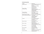
INSTALLATION AND
OPERATING INSTRUCTIONS
• Ariterm 35+
CONTENTS
General . ........................................................................................................ 2
Installation. ............................................................................................... 4-5
Installation of temperature limit valve....................................................... 6
Measurements and connections.................................................................. 7
Technical specifications and boiler cross-section...................................... 8
Operating principle...................................................................................... 9
Installation of grate and ceramic parts...............................................10-12
Operation....................................................................................................13
Heating..................................................................................................14-15
Service and maintenance............................................................................16
Use of alternative fuels...............................................................................17
Warranty and removal from use................................................................18
Most common spare parts.........................................................................18
Declaration of conformity..........................................................................19
Notes . ..................................................................................................20-23
2
GENERAL
The Ariterm 35+ is an economic, durable and environmentally-friendly, bottom fire, woodburning central heating boiler. Heating is periodic and based on storing energy in the warm
water accumulator tank. Usually this boiler is used for heating detached houses, farm buildings,
etc. Logs up to 50 cm long can be used as fuel. Light fuel oil can also be used if an oil burner is
fitted. In order to take advantage of all the features, it is important to observe the instructions
given in this booklet.
TRANSPORTATION, STORAGE AND OPENING THE PACKAGE
Receiving the goods
The boiler is delivered in a wooden frame. On the bottom is a pallet, which can be used to lift
the boiler safely. It is advisable to open the package as close as possible to the installation location. The factory insures the boiler against transport damage, which includes transport from the
factory to the first intermediate storage point. It is important that whoever receives the boiler
should check its condition before accepting it. In cases of damage, the seller must be contacted
immediately.
Storage
The boiler can be stored in the open air if protected from rain, but storage indoors is recommended.
Opening the package
After opening the package, open up all the hatches and check the equipment list to see that all
loose equipment has been supplied.
Disposal of packaging: plastic cover to the refuse tip, wooden planks can be burned.
INSTALLATION
Installation of the boiler can only be done by a company or individual with the necessary professional accreditations. Installation should be performed so that it meets the generally accepted
laws and regulations applicable to the industry. Electrical installation work must be done only
by a qualified electrician.
Space requirements
An area of 1 metre must be reserved in front of the boiler for cleaning and maintenance procedures. Above the boiler, a space at least as high as the height of the boiler must be reserved for
convection.
Flue connection and combustion air opening
Flue requirements for Ariterm 35+:
• Steel flue: height at least 4 m from the floor of the boiler room to the top of the flue, inner
diameter at least 150 mm
• Brick flue: height at least 4 m, free cross-sectional area at least 290 cm2
• For already existing flues, check the fire-technical suitability of the flue from your local fire
safety authority.
The free surface area of the combustion air opening must be about the same size as the flue.
This opening must never be covered.
Plumbing connections
Ariterm 35+ is intended for use with an accumulator tank. Before installation of the boiler, the
heating system must be flushed and a water pressure test carried out. The tightness of the connections must be ensured before installation. The factory is not responsible for damage caused
by leaking connections.
Safety vent installation
The vent must be CE-approved with a maximum opening pressure of 1.5 bar and a minimum
size of DN 15. The safety vent must be selected according to the highest pressure class of the
equipment assembly. No equipment may be installed between the vent and the boiler, as this
may interfere with the connection. The exhaust pipe must be dimensioned and installed so that
it neither restricts the exhaust efficiency of the vent, nor causes a hazardous situation when the
vent is in operation. The volume of the expansion tank must correspond to the greatest change
in fluid volume that occurs when the equipment is in use. In periodic heating, the expansion volume must be about 10% of the overall system volume. We recommend the use of only a closed
system (film expansion vessel).
4
INSTALLATION
The water returning to the boiler must be about 70°C. This is achieved by using a bypass connection in accordance with the circuit diagram. In order to maintain a sufficiently high temperature during the heating period, the convection surfaces should be kept clean, to ensure highly
efficient burning. The life expectancy of the boiler will also be increased, because corrosive acids
will not be created on the heating surfaces.
Part
Connection to boiler top
Ball check valve 1 ¼” IG
Thermometer
Internal thermal valve
Internal pump Wilo RS 25-6/3
Thermometer
Connection to boiler bottom
Filling connection R15
Thermometer
Ball check valve 1 ¼” IG
Connection to accumulator
tank bottom
Ball check valve 1 ¼” IG
Automatic cycle valve
in case of power cut
Easy-to-clean dirt pocket to
prevent operating errors
5
Name
1
Ariterm 35+ boiler
2
3-way valve, underfloor heating
3
3-way valve, radiator heating
4
Heat supply pump, underfloor heating
5
Heat supply pump, radiator heating
6
Underfloor heating system manifold
7
Radiator heating system
8
Expansion vessel
9
Service shut-off valve
10
Safety vent
11
Refill valve
12
Input mixing valve
13
Process water circulation pump
14
Thermal safety device
15
Accumulator switch
Laddomat 21 (LVI-5012912)
16
Warm water accumulator
INSTALLING THE TEMPERATURE LIMIT VALVE
The Pressure Vessel Directive requires that a manually-filled wood-burning boiler must be
equipped with a safety device, which prevents the boiler from overheating if circulation in the
accumulation tanks is prevented for some reason. The Ariterm 35+ boiler includes a cooling
spiral. We recommend the SYR 3065 temperature limit valve for this boiler. This does not, however, replace other safety devices such as a safety vent.
Installation
The temperature limit valve is connected to the cooling spiral or to the fork-junction in the
warm process water pipe so that when the valve operates, it sends hot water down the drain.
The temperature sensor is installed on the sleeve on the upper part of the boiler, using a DN 20
x 150 well.
TECHNICAL SPECIFICATIONS
Max. input water pressure
10 bar
Opening temperature
97° C
Valve available from Ariterm Oy
Product no. 5012912
6
DIMENSIONS AND CONNECTIONS
Part
Name
1
Turning plate adjustor
2
Water pressure gauge
3
Water thermometer
4
Combustion gas thermometer
5
Firebox hatch
6
Primary air damper
7
Secondary air damper
8
Unit
Part
Name
Unit
11
Fixed hatch for afterburning chamber
(hinged service hatch an option)
12
Safety valve connection
DN 20
13
Water accumulator outlet
DN 50
14
Water accumulator return
DN 50
15
Expansion unit
DN 25 outer thread
Refill hatch
16
Blow-off unit
DN 15
9
Convection cleaning hatch
17
Cooling spiral units
Cu 15
10
Convection ash removal hatch
18
Flue connection
19
Flue gas fan (A35-121D)
20
Boiler water temperature sensor pocket
7
168
TECHNICAL SPECIFICATIONS / BOILER CROSS-SEC
TION
TECHNICAL SPECIFICATIONS
Performance values:
Power
20 - 40 kW
Measurement data:
Width
Depth
Height
Weight empty
Water capacity
Storage chamber volume
Burning time
Size of refill opening
Chimney recommendation
800 mm
1109 mm
1300 mm
690 kg
150 L
120 L
37 kg / 3 h
550x350 mm
150 mm, 4 m
Design and adjustment values:
Boiler operating pressure
Permitted operating temperature
Suitable size of accumulator
Max. length of logs
0,5-1,5 bar
Max 120 °C
1800 – 3000 L
0,5 m
direct damper
storage chamber
afterburning
chamber
convection
section
grate
8
OPERATING PRINCIPLE
The Ariterm 35+ boiler is meant for use at full power, then complete gasification of the wood
will take place and the combustion will be clean. The amount of energy available from the boiler
to the accumulator will be optimal and the need for cleaning small. The boiler will also last longer with proper burning.
Wood gasification
This takes place at the grate at the bottom of the storage chamber. The primary air needed for
gasification rises through the plate-controlled damper to the carbonisation section, where the
wood gasifies. The refill hatch is inclined at an angle, so loading the wood into the storage chamber is easy and safe. Gas-powered dampers make hatch opening easy. The storage chamber expands as it goes further down, so is wide enough to ensure that wood does not get stuck against
the chamber walls. The chamber has a volume of 120 litres, which will accommodate about 37
kg of dry firewood. Burning time is three hours without having to add more wood, and the temperature in a 2000-litre accumulator will rise by about 50°C, if no heat is being used at the same
time.
Afterburning of gases
This takes place in a round ceramic chamber, into which pre-heated secondary is introduced.
Adjustment of the secondary air is done using the lower damper. The key factor in clean combustion is the complete mixing of combustion gases and pre-heated combustion air at a high
temperature. In the afterburning chamber, the temperature rises to almost 1000°C, at which
point different gases emitted from the wood ignite and are completely burned. The afterburner
chamber is a vertical cylinder and is made of ceramic parts.
Heat recovery
This takes place in the carefully dimensioned convection section, in which heat is efficiently
transferred from the super-heated combustion gases to the boiler water. The convection section
is vertical, so that fly-ash does not accumulate on its inner surfaces. Regular brushing of the convection section keeps the boiler efficient.
9
INSTALLATION OF THE GRATE AND CERAMIC COMPONENTS
It is advisable to carry our installation with the assistance of somebody else. Clean the boiler
well and carefully remove any pitch that may have accumulated, so that the parts will fit into
place. The grate should be installed before the ceramic parts through the firebox hatch, so that
the denser part of the grate goes backwards. Take care as the grate weighs about 50 kg.
The bricks should be installed through the opening at the side in the following order:
1. Lower brick
2. Lower parts of side brick
3. Lower part of front brick
4. Lower part of rear brick
5. Upper part of rear brick
6. Upper parts of front brick. The upper parts support each other with a suitably sized piece
of wood in between, for example.
7. Upper parts of side brick (2 pcs) (pay attention to left-or right-handedness). Remove the
temporary support then installation is complete.
1. Lower brick
2. Lower part of side brick (2 pcs)
2. Lower part of side brick (2 pcs)
3. Lower part of front brick
10
INSTALLATION OF THE GRATE AND CERAMIC COMPONENTS
3. Lower part of front brick
4. Lower part of rear brick
5. Upper part of rear brick
5. Upper part of rear brick
6. Upper part of front brick. The upper parts
support each other with a suitably sized piece
of wood in between, for example.
6. Upper part of front brick
11
INSTALLATION OF THE GRATE AND CERAMIC COMPONENTS
6. Upper part of front brick.
7. Upper parts of side brick (2 pcs) (pay attention to left-or right-handedness). Remove the
temporary support then installation is complete.
Installation of base bricks
1.
2.
3.
12
OPERATION
Introduction into use
Before running the boiler, check the following:
• the heating system and boiler are full of water, pressure at least 0.5 bar
• the heat supply pump is on
• the system valves are open
• the combustion air opening is open
• the safety vent is in unhindered contact with the boiler and is operational
• the relief valve is operational
• CHECK that afterburning chambers bricks are in right position.
First heating cycle
The boiler’s afterburning chamber is ceramic, and may contain moisture when new. In order to
ensure that the bricks dry out, it is advisable to keep the hatches open before heating if the boiler is inside. In the first heating cycle, keep a small fire going for about three hours, ensuring that
the combustion gas temperature does not exceed 140°C. After that, you can heat normally.
Basic adjustments
Adjustment of the damper:
1. Set the primary air regulators to position 3.
2. Set the secondary air regulators to position 5.
3. The recommended combustion gas temperature is under 140°C. The combustion gas temperature in question shows that the combustion temperature in the ceramic chamber is
sufficiently high for the ignition of all gases and for clean combustion. Under such circumstances, the boiler is at its most efficient and the need for cleaning minimal.
4. The recommended underpressure in the flue is 40 Pa, when the boiler is in operation. By
removing one mounting bolt from the flue gas fan, can measuring be done through the bolt
hole.
5. The draft can be adjusted from the control unit by changing the output power of the flue
gas fan.
13
HEATING
Lighting the boiler
Current regulations on limiting emissions resulting from wood burning have set major challenges on the development of combustion technology. As a result of the development, wood-burning boilers have become increasingly efficient and less and less firewood is required for heating.
These changes make the boilers more difficult to operate by natural means. Unless the boiler is
equipped with a flue gas fan, ignition by natural means is only possible with the help of adequate preheating.
The following instructions should be followed carefully when igniting the boilers:
1. The service hatch must be fully closed throughout the heating cycle. Check that both the
(upper) primary air regulators are set to position 3, and both the (lower) secondary air regulators are set to position 5.
2. Clean the grate and check that the surface of the ash that has accumulated underneath the
grate is not touching the grate.
3. Open the smoke damper and pull the turning damper out into the ignition position.
4. Check that the charger cycle is fully functional and double-check that the charging pump
thermostat is set to 65 degrees.
5. Start flue gas fan from control unit.
6. Insert the charge through the feed hatch onto the lower edge of the grate, all the way to the
afterburner opening, and light the fire.
7. Lay approximately 5 kg (an armful) of dry firewood of small diameter onto the charge, near
the afterburner opening. Close the feed hatch and leave the fire undisturbed for 15–25 minutes.
8. DO NOT ADD FIREWOOD UNTIL THE ENTIRE CHARGE LOAD HAS
CHARRED. Carefully open the feed hatch slightly and wait until the smoke is flowing
back into the boiler. Lay DRY firewood measuring no more than 50 cm in length into the
reserve box in a COMPACT and even formation. Position the wood in the fire box with
care.
9. Check that the wood catches fire. Burning wood makes a clear humming sound.
10. Once the wood has caught fire and the temperature has reached 150 degrees or higher, the
turning damper can be pushed into the heating position.
afterburning
chamber
Turning plate handle
Heating
Driftläge
position
grate
Pic 1
14
LightningTänd- ochand
lling position
påfyllningsläge
HEATING
Primary air hatch to pos 3
Secondary air hatch to pos 5
Refilling
Refilling is recommended when the storage chamber is about 1/3 full of wood.
1. Put the turning plate in the ignition position.
2. Slowly open the refill hatch, which will release the burning gases from the storage chamber.
3. Fill the storage chamber.
N.B. Fuel should only be refilled when the energy created can be stored in the accumulator tank or
otherwise consumed. Boiling of the accumulator tank and boiler must be avoided.
15
SERVICE AND MAINTENANCE
Cleaning
1. Before cleaning the boiler, it is advisable first to heat it, preferably with softwood, in order
to make it easier to remove soot. Clean the boiler’s convection section 2-4 times per month
and whenever required.
2. Once the fire has gone out but the boiler is still hot, open the cleaning hatch on top and
brush/scrape it clean.
3. Open the cleaning hatch at the side and remove any loose incrustation with an ash scraper.
4. Open the firebox hatch, clean the grate and empty the ashbox into a fire-proof ash bucket.
N.B. The surface of the ash must never rise up to touch the grate. This prevents cooling of the grate
and will rapidly result in damage. For this reason too, the holes in the grate must be open.
Ensuring the tightness of the hatches
All pitch, etc. must be removed from the hatch seals and sealing surfaces. If leaks appear in the
hatches, these must be eliminated. This can be done by turning the locking pin cam to a different position. If this does not help, the seals must be changed.
16
THE USE OF ALTERNATIVE FUELS
Use of an oil burner
An oil burner can be installed in the burner opening on the side of the boiler, either with or without the use of the quick-change hatch. When using the quick-change hatch, a hatch coupling
must be fitted. The burner must always be removed from the combustion chamber when solid
fuel is being burned. All hatches and air openings must be tightly closed when using an oil burner.
Use of electricity
No electrical resistors can be installed in this boiler. They should be fitted in the accumulator
tank.
Pellet use
Ariterm 35+ is compatible with an KMP PX22 pellet burner. Replace the stoking hatch with
a hatch with an PX22 pellet stoker. If you use a pellet burner, close primary and secondary air
vents. Specified instructions on the installation and use of the pellet burner come with the burner.
17
WARRANTY AND REMOVAL FROM USE
Warranty
For Warranty Issues Ariterm Sweden AB refers to our local Distributor.
Removal from use
A boiler that has reached the end of its life can be used for scrap.
MOST COMMON SPARE PARTS
Part number
Name
Additional information
Quantity
13863
Plane grate
13886
Askew grate
13611
Front brick lower
545x115x109
1
13612
Rear brick lower
545x126x88
1
13613
Lower brick
446x255x50
1
13614
Side bricks lower part
50x150x275
2
13615
Side bricks upper part left
50x131x322
1
13616
Side bricks upper part right
50x131x322
1
13617
Front brick upper
545x104x215
1
13618
Rear brick upper
545x210x137
1
13375
Gas spring
2
5880
Thermometer
1
5883
Combustion gas thermometer
0-500 °C
1
5882
Pressure gauge
1566 SWOY
1
10040
Brush
40x80x110 M12
1
3492
Brush arm
1250 mm
1
5805
Locking pin sleeve
inc. screws
1
1
1
18
DECLARATION OF COMFORMITY
19
NOTES
20
NOTES
21
NOTES
NOTES
23
- All Rights to modifications and corrections reserved.
2011.05.04
ARITERM SWEDEN AB | Flottiljvägen 15
39241 Kalmar | www.ariterm.se | 0771-442850