1
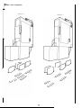
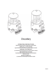
=7:~NEL
SERVICE
MANUAL
I
2
1.0
2.0
3
3.0
4.0
I
4.1
4.2
General Description
General Description
The Sentinel coin mechanism is the first of a new family of products based
on Coin Controls’ new cash handling concept of Flexible Cash Modules.
Interface Connections
It uses the latest in coin handling technology to offer a product with an
Sentinel Mechanical Description unparalleled combination of performance, features and value for money.
Factory Fitted Coin Entry and
The key feature of Sentinel is flexibility. By selection from the carefully
exit options
designed system of mechanical sub-modules, Sentinel can be configured
to suit any 5” size coin mechanism application.
Front Entry
Sentinel Versions 30 and 35
4.3 Top Entry
Sentinel Exploded diagram
5.0 Coin Sorting
5.1 Corn Sorter Module
5.2 Removal and Replacement of
Sentinel has the following features:Standard 5” size
Up to 8 coin validation
Industry standard parallel interface with automatic selection
IIC serial communication port
Sorter
6.0 Mechanisms Internal Access
Mechanism
Removal
and
installation in Machine
Electrical Interface Specification
Field programmability of active 4 way sorter routing.
Corn output configuration compatible with existing AWP’s when one
of two optional manifolds are fitted.
Power Supply
Parallel
Interface
Using the Parallel Interface
I Routine Maintenance
1 1.0
On Site Testing
I
VERSIONS
2.0
S entinel Versions 30 and 35
T here are two versions of the Sentinel 30 series of coin acceptors. These are the Sentinel 30, which does not
h ave a sorter, and the Sentinel 35 which has a full 4 way active sorter fitted.
B oth versions are available with either Front Entry or Top Entry options. The Front Entry option is available
with direct or indirect reject the Top Entry being available with Indirect reject only.
T he versions in common usage are shown in Figures I to 5 below.
F IGURE I SENTINEL 30 TOP ENTRY
Thls shows the Top Entry version without the
active sorter, for back channel mounting.
This version may be used in Juke Boxes and
vending applications where no coin sorting for
payout is required and where front panel space
IS II mited.
TopEntry
Accept Outlet
Reject
FIG 2.
FIGURE 2 SENTINEL 35 TOP ENTRY
T h i s shows the Top Entry version fitted with the
a c tive 4 way sorter, which may be site
programmed. Applications for this version include
vending with change.
FIG 3.
30 FRONTPLATE,
INDIRECT REJECT
IGURE 3 SENTINEL
This is the Front Entry version without the active
orter, and may be in either direct or indirect
machine) reject options. Applications for this
version Include Juke boxes, Vending and Video
nachines where front panel space is avaliable.
FIG 4.
35 FRONTPLATE.
DIRECT REJECT
FIGURE4 SENTINEL
This is the Front Entry version fitted with the active
4 way sorter, and may be in either direct or
Indirect (machine) reject options. Applications for
this version Include AWP, SWP and vending with
change.
\
’
FIG 5.
35 FRONTPLATE.
INDIRECT + MANIFOLD
FIGURE 5 SENTINEL
This the Front Entry version with active 4 way sorter
fitted, with the addltlon of a manifold.Thls version will be
found in current AWP and SWP machines. This version
is available in in dlrect reject only.Two versions of the
manifold are available and are shown in figure 6.
FIG 6.
Manifold 5 and 6 configurations
MANIFOLD 5
I
MANIFOLD 6
SENTINEL
EXPLODED DIAGRAM
FIG 7
Parts List
I Coin entry and button
housing
2 Button
3 Button lid
4 Button cone spring
5 Button label
6 Quick release latch
7 Main body
8 M4.0 x 16.0 pozi pan HD
screw
9 Front entry gate piece
IO Gate snubber
I I 4.20 x 3/8" pozi CSK screw
I2 Quick release latch
spring
I3 Front entry
14 2nd sense coil assembly
15 Bulb
I6 Lamp holder
17 M4.0 full nut
I 18 I st sense coil assembly
19 4.20 x 5/16" pozi pan HD
20 3rd sense coil
21 Main body pole piece
22 P.C.B. cover plate
23 Solenoid assembly
24 Hinge pin spring
25 Main body snubber
26 Hinge pin
27 Sorter coin diverter flap
28 Final accept coil
assembly
29 Printed circuit board
assembly
30 4.20 x 5/8 pozi pan HD
screw
3 I Sorter centre plate
32 Coin diverter flap spring
33 Sorter solenoid flap
34 Solenoid flap pole piece
35 6.20 x 1/4" pozi pan HD
screw
36 Solenoid coin flap
assembly
37 Sorter solenoid cone
spring
38 Sorter solenoid cover
39 Coin rundown and reject
cover
40 Accept gate
41 Accept gate spring
42 Reject gate
43 Mech. mounting studs
44 Front plate
45 M3.0 x 6.0 pozi pan HD
screw
46 Cotton catch
47 Photo Cells
51I Top entry chute
52 Top entry gate piece
53 Top entry reject lever
54 Top entry reject lever
pivot screw
55 Top entry reject lever
spring
56 Reject cup
57 Reject cup flap
58 M3.0 x pozi pan HD
59 Single corn outlet
I
5.0
C oin Sorting
Coin sorting is performed by the optional four way plug in active sorter. Coin sorting is fully flexible (any coin
any way) and is programmed by values STORED IN SENTINEL EEPROM IN THE COIN VALIDATOR
A SSEMBLY.
There are six coin sorting functions which may each be programmed to any of the eight coin channelsCoin always diverted down sorter path A’
Coin always diverted down sorter path B
C oin always diverted down sorter path C
Coin always diverted down sorter path D
C oin toggles alternately down sorter paths A & B
C oin toggles alternately down sorter paths C & D
VIEW FROM BOTTOM OF MECH
FIG 8.
T he last two sorter functlons are lntended for club machlnes or any application where two pay out devices for
the same coin value are required.
5. I
Coin Sorter Module
When fitted to the assembly the sorter allows four way sorting. This is achieved by two Integral flaps (27,36)
which are actively driven by two solenoids(23B,23C). The first flap (36) is a metal Construction, which diverts
the coin to one of the ports A or B at the back of the assembly when the solenoid(23C) is not energised , and to
0 ne of the ports C or D near the centre of the mechanism when the solenoid is energised. The long plastic
diverterflap (27)which runs the length of the sorter is used to select between ports A and B or between ports
C and D under the control of the solenoid (23B).
Two sets of photo cells(47) are located at the bottom of the sorter, which reset the solenoids and allow the
assembly to accept further coins immediately after the coin has cleared the cells. This eliminates any timing
complication.
The default path of the sorter (i.e. no solenoids energised) is path A. With reference to the sorter output paths
diagram it can be seen that if a solenoid fails to operate, it will cause a coin to tend toward the A side of the
sorter i.e. Top solenoid fail will cause coins from C to go down A and D to go down B. similarly if the bottom
solenoid falls, coins from B will go down A, and coins from D go down C.
The sorter paths are programmed into the Sentinel validator assembly on manufacture to the customer
requirements Note that replacement of a sorter does NOT require any reprogramming,
but that
replacment of the complete mech MUST be with one with the same sorter paths (as shown on the mech
I abel). The Sentinel may be reprogrammed for other
coin paths using the Sentinel Toolkit.
5:2
I Removal and Replacement of Sorter
The sorter can be unplugged once the cover and snubber are removed -see Mechanism Internal Access 6.0.
When reassembling a sorter onto the mechanism body ensure that the diverter flap (27) does not become
trapped between the sorter body and the mechanism. This is most easily ensured by offering the mechanism
I body down onto the sorter module. Ensure that the 4 connector pins are al igned correctly with the sockets in
the mechanism body. Once the sorter is fitted correctly, refit the snubber (25) and cover (39), securing with
screw (I 9C).
6
6.0
Mechanism
Internal
Access
1
to parts required for on site service is by removal of the screw (I 9C). Note the position of the metal
nubber (25), and ensure that it is refitted correctly on reassembly of the mechanrsm.
Mechansim Removal and installation in Machine
To remove the body from the front plate, disconnect any serial or parallel Interface connectors Hold the
mechanism across the top, and pull the locking catch (6) toward you with one finger. Raise the mechanism as far
as it will go without pulling the mechanism toward you. withdraw the mechanrsm by pulling gently toward the
-ear of the machine. Note thatthere is no sldeways movement in removing the Sentinel acceptor. lnstallation IS
he reverse of removal, except that the locking bar will engage automatically when the acceptor is properly
located.
Electrical
ELECTRICAL
SPECIFICATION
POWER SUPPLY
REQUIREMENTS
Interface
Specifications
IMPORTANT NOTE
Application of signals or voltages outside specification may cause damage to or malfunction
8.1
Power
of the mechanism
Supply
Voltage:
I I to 15 volts DC
Current:
220 mA continuous.
0.7 A maximum (no sorter fitted)
2.0 A rnaximum (with sorter fitted)
Rise time:
200 rnsec maximum
It is important to ensure sufficient power supply current capacity. A minimum capacitance of 4700 microfarads
IS recommended on the machine power supply output rail.
8.2
Parallel
Interface
COM A:
+5 to +20V DC, -5 to -20V DC
200 mA maximum
Al to A4:
8 mA source at COM A = +5V
50 mA source at COM A = +9V to •t 24V
20 mA sink at COM A = --5V
SO mA sink at COM A = -I0V to -20V
Pulse length + 80msec +/- 20%
9.0
I I to I7,8:
Internal pull up to 5V DC
Open circuit or > 3.6V = inhibit
Short circuit to OV or < I .2V = accept
SELECT
internal pull up to 5V
Open circuit or > 3.6V = 4 coin
Short circuit to OV or < I .2V = 8 coin
Using the Parallel Interface
The parallel Interface provides open collector output signals which will automatically
to COM A and select pull up or pull down output drives as required.
All parallel interface
signals are routed via connector I, and the following signals
Pin No.
Signal Name
Signal Description
Supply input for accept output drive
1
COM 4
2
Al
Accept output Coin I
3
NC
Polarising position
4
A2
Accept output Coin 2
5
A3
Accept output Coin 3
6
Select
4 coin/8 Coin select line
7
A4
Accept output Coin 4
8
14
9
10
v supply
0 volts
Inhibit acceptance Coin 4
Power supply Input
Machine
0 volts supply
13
Inhibit acceptance Coin 3
12
12
Inhibit acceptance Coin 2
13
II
Inhibit acceptance Coin
14
15.6
Inhibit acceptance Coins 5 and 6
15
17.8
Inhibit acceptance Coins 7 and 8
1I
7
1
sense the voltage applied
are available on this connector
outine
Maintenance
T h e plastic coin run down should be cleaned periodically Access to the run down is gained by
folding back the reject flap and removal of the screw (19C) and cover (39). Note the position
the snubber (25) and ensure it is refitted correctly on reassembly. Remove the sorter module
described - see COIN SORTER MODULE. Cleaning of the sorter module may then also be
carried out.
T h e cleaning
materials
recommended for the Sentinel Corn acceptor are as follows:-
Mild detergents and water, using a damp cloth.
Foam cleaners providing they are not acetone based.
under no circumstances should any acetone or ketone based cleaners be used on the acceptor
- sorter. Silicone spray polishes should never be used as these will reduce the static protection
corporated in the acceptor plastic
11.0
On Site Testing
before replacement of the mechanism, please check the following pointsMechanisim correctly
installed in Front Plate/Back Channel. Gate assembly correctly closed
Mechanism rundown not obstructed Corns not backed up into the mechanism from underneath
Mechanism rundown is clean-see Routine Maintenance
Symptom
Mech does not work
( a l l coins reject)
Investigate
Possible Cause
Connector
Poor contact
Bent pins
Power supply
+ 12V NOMINAL
+ I IV MINIMUM
Not switched
on
Incorrect voltage
NOTF Supply voltage must not drop below this absolute minimum. A meter
may not detect transients that may occur on acceptance of a coin Use of the
Toolkit advised.
30
Inadequate power
700mA
35
2A
Power supply Rise
200mSec max
Time too slow
Inhibits inputs
> I .2V for ACCEPT
Accept Gate
Mech takes first coin
and then stops working
True coin reject
too often
Coins stick or jam
in mech
Mech inhibited
Gate not free or
dislocated
Accept Channel
Obstruction in
Channel
Parallel
parallel/ Interface
Interface
- 20V to 0v
+5v to +24v
COM A pin not
connected. Voltage
out of limits
Serial Interface
(If connected)
Host Machine not
responding
Power supply
11-15v
Voltage out
of specification
Accept Gate
Flap not free or
dislocated
Connector
Loose
Rundown
Dirty
Sorter opto
detectors
35 only
Failed Mech times
out after 2 seconds,
giving poor accept
rate when coins are
fed fast, but is
alright when fed at
I coin/3 seconds.
Rundown
Accept channel
Reject channel
Accept Gate
Sorter (If fitted)
Dirt or mechanical
damage/obstruction
Mounting of mech
Body and/or sorter
Improperly
mounted
8
One of the true
coins always
r ejects
(if connected)
Coins I” wrong
.ashbox
No accept signal
dent or broken
connection pin
< 1.2v
I
for accept
Wrong inhibit
input voltage
< I 1.6V = ACCEPT
Accept
Flap spring
loose or flap
dislocated
flap
Sorter
Dirty, mechanical
damage or obstruction
Solenoid failure or
wire broken
Connector
Accept channel
Connector loose or broken
Dirty or obstructed
f any of the defects cannot be rectified, then the mechanism
ame sorter paths as shown on the faulty mech label
should be replaced with one programmed to the
Return the faulty acceptor to Coin Controls for repair. We do not recommend that any rectification
attempted on the main electronics assembly.
The mechanism
warranty.
is covered by a warranty from Coin Controls and unauthorised
For spares and service
rectification
is
may invalidate this
contact Coin Controls Technical Sales Department. Telephone: 06 I -678 0 I I I.
9