1
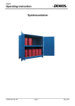
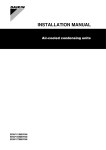
System container
System container 2G 614.O with sliding doors
OPERATING INSTRUCTIONS
Mat.-No. 130406 EN BA System container
02/2008
OPERATING INSTRUCTIONS
Table of contents:
1. General Points ................................................................................................................... 3
2. Intended use ...................................................................................................................... 3
3. Product description........................................................................................................... 3
Assembly ............................................................................................................................ 3
4. Technical Details ............................................................................................................... 4
4.1 Explanation of model codes........................................................................................ 4
4.2 Tables: Dimensions and load capacities ................................................................... 4
5. Transport............................................................................................................................ 6
6.Assembly............................................................................................................................. 6
6.1 Location of the container ............................................................................................ 6
6.2 Securing the container to the floor............................................................................. 8
6.3 Assembling the container part by part including the sliding doors ........................ 9
6.3.1 Tools required ......................................................................................................................................... 9
6.3.2 List of parts to assemble the upper and lower components of the container ......................................... 9
6.3.3 Lower and upper levels of the container ............................................................................................... 10
6.3.4 Assembling the upper and lower levels of the container ...................................................................... 11
6.3.5 Detailed diagrams of the upper and lower levels picture 1-4................................................................ 11
6.3.6 Over view of the sliding doors ............................................................................................................... 14
6.3.7 Parts list for the sliding doors ................................................................................................................ 15
6.3.9 Detailed diagrams of the sliding doors pictures 6 – 11 ......................................................................... 16
6.4 Earthing the naturally ventilated containers ........................................................... 19
7. Operation.......................................................................................................................... 19
7.1 For storage indoors and outdoors ........................................................................... 19
7.2 Advice when dispensing ........................................................................................... 19
8. Maintenance and Repair ................................................................................................. 20
9. Spare List ......................................................................................................................... 20
10. Optional equipment ....................................................................................................... 20
11 Appendix ......................................................................................................................... 21
Please find general operating instructions and proof of conformity, attached
130406 DE BA System container
Page 2 of 25 Pages
Edition02/2008
OPERATING INSTRUCTIONS
1. General Points
These operating instructions are applicable to system containers and system containers with natural ventilation. They specify all the information necessary for their correct operation. The advice and instructions mentioned in the booklet are to be observed and adhered to.
If the product is used in accordance with the regulations corresponding to these operating instructions, we
will be liable in line with our guarantee conditions.
No modifications or alterations can be made to the product without authorisation from the manufacturer. The manufacturer will not be liable for any modifications made without their authorisation and the
guarantee will expire and cease to be valid.
The general instructions for storage systems, material no. 103041, in the current version,
must be observed.
National standards and safety regulations must be observed.
It is forbidden for fire or naked flames to be in close proximity to the system container. Smoking is also prohibited.
2. Intended use
System containers with natural ventilation are ideal for the passive storage of water hazardous materials and materials included in hazardous materials classifications R10, R11 or R12 in accordance with hazardous materials classifications (also, please see section 3).-.
- Only store substances that the sump material is resistant to. See general operating instructions
- Versions equipped with PVC panels or roller doors are not permitted for storage of inflammable
liquids
3. Product description
Assembly
The system containers are assembled from the following components:
-
Frame construction made from hollow and shaped sections in accordance with static requirements
Side panels and roof made from galvanized sheet
Rear panel made from trapezoid profiled sheet
Sump manufactured from steel S235 JRG2 according to DIN EN 10025
optional sump insert made from steel or PE
Optional wing doors, sliding doors, PVC panels or roller doors can be fitted to the front of the container
130406 DE BA System container
Page 3 of 25 Pages
Edition02/2008
OPERATING INSTRUCTIONS
4. Technical Details
4.1 Explanation of model codes
3 G 3 14. O ST - S
(Example)
naturally ventilated container
options for closing
the container:
TE
ST
P
RT
= wing door
= sliding door
= sliding panel
= roller door
External cladding:
O
I
= with roof
= without roof
depth of the container in m x10 (without an option for closing the container
width of the container in m (rounded up to the nearest figure)
A
G
K
P
Type of storage:
= storing drums horizontally
= storing drums vertically
= storing IBCs
= storing containers on pallets
Number of storage levels
4.2 Tables: Dimensions and load capacities
Standard-System container for storing drums vertically outdoors
Model
1G 314.O
2G 314.O
3G 314.O
1G 614.O
2G 614.O
3G 614.O
1G 326.O
2G 326.O
3G 326.O
1G 626.O
2G 626.O
3G 626.O
Width (mm) Depth (mm
3000
1310
2 x 3000
3000
2 x 1270
2 x 3000
Height
(mm)
1 x 2640
2 x 1250
3 x 1250
1 x 2640
2 x 1250
3 x 1250
1 x 2640
2 x 1250
3 x 1250
1 x 2640
2 x 1250
3 x 1250
Load caSump capacpacity
ity (ltr)
(kg/m2)
Load (kg)
750
4200
1500
1000
1300
3900
2540
2900
Standard-System container for the external storage of pallets
Model
2P 414.O
3P 414.O
2P 814.O
3P 814.O
Width (mm) Depth (mm
3900
1310
2 x 3900
130406 DE BA System container
Height
(mm)
2 x 1250
3 x 1250
2 x 1250
3 x 1250
Load caSump capacpacity
ity (ltr)
(kg/m2)
Load (kg)
1100
1000
5460
2100
Page 4 of 25 Pages
Edition02/2008
OPERATING INSTRUCTIONS
Standard-System container for the external storage of IBCs
Model
Width (mm) Depth (mm
1K214.O
2K214.O
1K 414.O
2K 414.O
1K 514.O
2K 514.O
1K 714.O
2K 714.O
Load caSump capacpacity
ity (ltr)
(kg/m2)
Height
(mm)
1 x 2570
2 x 1500
1 x 2570
2 x 1500
1 x 2570
2 x 1500
1 x 2570
2 x 1500
2700
3380
1310
2.x.2700
2 x 3380
1000
Load (kg)
4725
1180
5915
1250
2000
4725
2400
5915
Standard-System containers and for storing drums horizontally outdoors
Model
Width (mm) Depth (mm
2A 314.O
3A 314.O
2A 614.O
3A 614.O
Load caSump capacpacity
ity (ltr)
(kg/m2)
Height
(mm)
2 x 1165
3 x 750
2 x 1165
3 x 750
3000
1340
2 x 3000
Load (kg)
470
350 kg/drum storage space.
1000
Standard-System container for the storing drums vertically indoors
Model
Width (mm) Depth (mm
1 x 1250
1 x 500
2 x 1250
1 x 500
1 x 1250
1 x 500
2 x 1250
1 x 500
2G 314.I
3000
3G 314.I
1310
2G 614.I
2 x 3000
3G 614.I
Compliance:
Load caSump capacpacity
ity (ltr)
(kg/m2)
Height
(mm)
Load (kg)
750
1000
4200
1500
System containers are compliant with construction regulations No. Z-38.5-120.
Zul.-Nr.: Z-38.5-120
System containers have also been tested and are approved for the following:
Load capacity:
maximum wind resistance: Î 0,5 kN/m2 in accordance with DIN 1055 Part 4,
see Tables: Dimensions and load capacities
Resistance in snowy
conditions (roof load):
130406 DE BA System container
Î 0,75 kN /m²
Page 5 of 25 Pages
Edition02/2008
OPERATING INSTRUCTIONS
5. Transport
Do only transport when empty!
System containers without crane hooks can be loaded and transported with an appropriately sized fork lift
truck.
When transporting system containers with crane hooks, the angle of the ropes must not be less than 45°.
See the “load position” diagram.
•
Load position
Container models:
314 / 414 / 326 / 426
Please note: the ropes in the
middle must be taught
Container models:
614 / 714 / 814 / 626 / 826
6.Assembly
6.1 Location of the container
System containers can only be installed on level and stable surfaces. The whole construction from the sides to
the foundation must be designed so that the loads specified can be contained securely. A competent person
will decide which type of concrete the container will be installed on taking into account the requirements in the
location of the installation; the load capacity, what the container will store and durability in accordance with
DIN EN 206 (also please see the foundation plan). Other requirements can be found in the general operating
instructions.
•
-
-
Correct installation position of the container (indication of the alignment of the door)
The signs above will be will be fixed onto the wing doors in the factory to show the horizontal
alignment of the doors
The arrows show that the doors are aligned
If the points of the arrows face each other the container is balanced and the doors will open and
close correctly.
If the points of the arrows do not face each other then the doors will not open and close correctly.
In this situation the container must be supported (for example with spacer plates) to ensure that the
130406 DE BA System container
Page 6 of 25 Pages
Edition02/2008
OPERATING INSTRUCTIONS
ground beneath the container is no longer uneven and the container can then be balanced
The system container can be installed indoors or outdoors. Please observe and adhere to the following installation instructions (see pictures 1-3).
Picture 1
Arranging the containers in a block, max. 4 containers;
2 containers fit together in 2 rows one behind the other!
Picture 2
Containers can be arranged in a row,
no limit on the number of containers!
Picture 3
min. 1 m
2 containers can be fitted in a row together against a wall!
130406 DE BA System container
Page 7 of 25 Pages
Edition02/2008
OPERATING INSTRUCTIONS
6.2 Securing the container to the floor
Balance the container using a spirit level. If necessary use supports to balance the container (for example
spacer plates). See the diagram “securing foot plates to the ground”.
•
Diagram „securing foot plates to the ground“
foot
foot plate
screw M16x40
nut M16x125 and
raw bolt M16
square washer DIN 436-17,5
The foot plates are secured in place with the nuts and raw bolts. See pictures 1-3 for the position and
quantity of the nuts and raw bolts.
Picture 3
Container models: 614 / 714 / 814 / 626 / 826-OST
Quantity of nuts and raw bolts: 7 - 8
Picture 1
Container models: 314 / 414 / 326 / 426-O
and OTE
Quantity of nuts and raw bolts: 4
Picture 2
Container models: 614 / 714 / 814 / 626 / 826O,OTE and ORT
Quantity of nuts and raw bolts: 6
130406 DE BA System container
Page 8 of 25 Pages
Edition02/2008
OPERATING INSTRUCTIONS
6.3 Assembling the container part by part including the sliding doors
At least 2 people are required to assemble the system container. The ground must be level and suitable for
securing the foot plates.
6.3.1 Tools required
- Fork lift truck with an access safety platform (for the assembly of the lower level, upper level and the
doors)
- Spirit level (for aligning the container)
- Mandrel ∅ 12 x 100 mm (to align the upper and base parts)
- Combination wrench SW 19 and SW 24 (to tighten screws and dowels)
- Vice (2, to hold the panels)
- Cordless screw driver (Assembling the panels)
- Silicone syringes (Sealing the panels)
- Hammer drill with masonry drill bit ∅ 18 x 200 mm (Drilling for nuts and raw bolts)
6.3.2 List of parts to assemble the upper and lower components of the container
Pos.
Description
Quantity
1
Lower level of the system container
1
2
Upper level of the system container
1
3
Foot plates
6
4
Side panel
2
5
Rain deflector on the rear panel of the container
2
5.1
Rain deflector on the rear panel of the container
1
6
Hexagonal screw M16 x 40 ISO-4017 (DIN933)
12
7
Hexagonal bolt M16 ISO-4032 (DIN934)
12
8
Washer d=17 ISO-7089/7090 (DIN125)
24
9
nut M16 x 125
7
10
Raw bolt M16 x 190
7
11
Square washer d=17,5 (DIN436)
7
12
Hexagonal screw M12 x 100 ISO-4017 (DIN933)
4
13
Hexagonal bolt M12 ISO-4032 (DIN934)
6
14
Washer d=13 ISO-7089/7090 (DIN125)
8
15
Square washer d=14 (DIN434)
4
16
Hexagonal screw M12 x 160 ISO-4014 (DIN931)
2
17
Self drilling screw 4,8 x 16 (DIN7504)
40
130406 DE BA System container
Page 9 of 25 Pages
Edition02/2008
OPERATING INSTRUCTIONS
6.3.3 Lower and upper levels of the container
The separated container model 3G 614.O
Crane hook
2
Picture
4
Picture 3
5.1
4
5
1
3
Picture 2
Picture 1
130406 DE BA System container
Page 10 of 25 Pages
Edition02/2008
OPERATING INSTRUCTIONS
6.3.4 Assembling the upper and lower levels of the container
1. Place the lower level of the container (1) on a level, stable surface using a fork lift truck and balance the
container using a spirit level. Support the foot plates with spacer plates if required.
2. Pace the upper level of the container (2) on the lower level with a fork lift truck (1) and align with the
mandrel.
3. Screw the left and right side frames and the middle frame together with hexagonal screws (12, 13, 14, 15
und 16), (see picture 3 „Screwing the upper and lower levels together“).
4. Push the rain deflector on the rear panel of the container (5 and 5.1) behind the trapezoid profile of the
upper level. Assemble the short rain deflector in the middle of the container, both the 3 metre long panels should overlap at approx. 30mm Place the rain deflector on the trapezoid profile using self drilling
screws (17). Screw the self drilling screws (17), (see picture 4 „rear rain deflector“).
5. Screw the side panels (4) on the outer side of the right and left hand sides of the container with self drilling screws (17), (see picture 3 Screwing the upper and lower levels together“).
6. Seal the upper edges of the side panels with silicone.
7. Dowel the foot plates (3) with the nuts and raw bolts (9, 10 und 11) together in accordance with the
manufacturer’s specifications, (see picture 1 „foot plate“).
8. Containers with sliding doors are supported at the front by 2 feet and nuts and raw bolts, (see picture 2
„centre of the footplate“ and point 6.2 „securing the container to the floor“).
6.3.5 Detailed diagrams of the upper and lower levels picture 1-4
Picture 1 „Foot plate“
11
6, 7, 8
9, 10
130406 DE BA System container
3
Page 11 of 25 Pages
Edition02/2008
OPERATING INSTRUCTIONS
Picture 2 „Centre of the
foot plate“
3
Picture 3 „Screwing the upper and lower levels
together“
12, 13, 14, 15 (frames for the left and right sides)
13, 14, 16 (frame for the centre)
Seal the edge of the container with
silicone
4
17
130406 DE BA System container
Page 12 of 25 Pages
Edition02/2008
OPERATING INSTRUCTIONS
Picture 4 „rear rain deflector“
Trapezoid profile
17
5, 5.1
130406 DE BA System container
Page 13 of 25 Pages
Edition02/2008
OPERATING INSTRUCTIONS
6.3.6 Over view of the sliding doors
1
1
321
2
305
2
306
311
316
310
315
325
351
(self drilling screws ∅ 6,3 x 19
approx. every 300 mm)
130406 DE BA System container
320
325
Page 14 of 25 Pages
Edition02/2008
OPERATING INSTRUCTIONS
6.3.7 Parts list for the sliding doors
Pos.
Bezeichnung
Stückzahl
1
Left sliding door panel (for the front runner)
1
1
Left sliding door panel (for the front runner)
1
2
Right sliding door panel (for the back runner)
1
2
Right sliding door panel (for the back runner)
1
18
Plate for holding the left door stopper
1
19
Locking plate for the sliding door
1
20
Bracket for the central sliding door stop
2
21
Bracket for the right sliding door stop
1
22
Bracket for the left sliding door stop
1
305
Cladded face plate for sliding doors (all models)
2
306
Cladded face plate for sliding doors (model G 614.O)
2
310
Sliding door face plate on the left model 3G / 3P
1
311
Sliding door face plate on the left model 3G / 3P
1
315
Sliding door face plate on the right model 3G / 3P
1
316
Sliding door face plate Re / Lock model 3G / 3P
1
320
Face plate for the lower door lock
1
321
Face plate for the upper door lock
2
325
Bars for the doors 1982 lg
4
351
Hexagonal screw 6,3 x 19-K, galvanized., (DIN 7504)
50
410
Roller mechanism
4
411
Guide roller
2
412
KST - runner
2
413
Black synthetic handle
2
414
Clamp for the swing bolt
1
415
cylinder
1
416
WSS-plate around the keyhole
1
417
Door stopper H=35 D=40
1
512
washer 6,4 x 20
2
513
Hexagonal screw M 6 x 40 ISO 4017
1
514
Acorn nut M 6
1
516
Countersunk screw M 5 x 16 ISO 7046
4
517
Countersunk self drilling screw 6,3 x 25-K, galvanized., (DIN 7504)
14
518
Internal cylinder screw 6kt. M 6 x 20
4
520
Cross self drilling screw 4,8 x 19-N, galvanized, (DIN 7504)
40
521
Flat headed screw with a groove
2
130406 DE BA System container
Page 15 of 25 Pages
Edition02/2008
OPERATING INSTRUCTIONS
6.3.8 Assembling the sliding doors
1. Screw the roller mechanism (410) into the left (1) and right (2) door panels. The head of the screw
should have approx. 35mm gap from the door, (see picture 6 „Sliding door roller mechanism“).
2. Guide the roller mechanism (410) into the runners.
3. Please note: The bracket needs to face outwards!
4. Hang the right (2) and left (1) door panels onto the roller mechanism. Firstly, hang the right door panel
(2) on the back runner and then the left door panel (1) on the front runner.
5. Balance the doors and adjust the roller mechanism.
6. Put the door together using the bars for the doors (325) and the self drilling screws (351), (see „Overview
of the sliding doors“). Screw the self drilling screws (351) in at intervals of 300 mm.
7. Fix the left, right and centre sliding door guide rollers in place, (see picture 7 „sliding door guide roller
bottom centre“, picture 8 „sliding door guide roller bottom right“ and picture 9 „sliding door guide roller
bottom left“).
8. Please note! Fix the brackets for the right (21) and left (22) sliding door stop at intervals of 38mm on the
front edge of the door!
9. Put the locking plate for the sliding door (19) on the right door panel (2), (see picture 11 „central lock for
the sliding doors“).
10. Put the clamp for the swing bolt (414), handle (413), cylinder (415) and WSS plate around the keyhole
(416) together.
11. Assembling the sliding door stoppers (417), (see picture 10 „ left sliding door stopper“). The stopper
needs to be fixed in place centrally at a height of 1500 mm.
12. Assemble the horizontal face plates for the door (305 und 306) and the vertical face plates for the door
(315, 316, 320 und 321) as shown in the „overview of the sliding doors“.
6.3.9 Detailed diagrams of the sliding doors pictures 6 – 11
Picture 6 „Roller mechanism“
runners
410
305
306
Bracket must face outwards!
520
Screw
(head of the screw
approx. 35 mm gap from
the door)
2
130406 DE BA System container
Page 16 of 25 Pages
1
Edition02/2008
OPERATING INSTRUCTIONS
Picture 7 „Sliding door guide rollers bottom left
70
411
62
517
138
100
150
20
45
1
43
20
36
Picture 8 „Sliding door guide roller bottom right“
38
21
Bracket for the
right sliding
door stop (21)
38 mm gap
from the edge
of the front
door panel
70
40
40
12
517
521
412
Picture 9 „Sliding door guide roller bottom left“
40
109
12
70
517
38
40
22
412
521
130406 DE BA System container
Page 17 of 25 Pages
150
Bracket for
the left sliding door stop
(22)
38 mm gap
from the
edge of the
front door
panel
Edition02/2008
OPERATING INSTRUCTIONS
Rechter Torflügel geöffnet!
Picture 10 „Stopper for the left sliding door“
Right door panel opened!
35
12
100
417
135
2
512
2
513
137
517
514
18
517
6
3
Picture 11 „central lock for the sliding doors“
9
19
20
516
416
414
413
130406 DE BA System container
415
35
35
Page 18 of 25 Pages
518
Edition02/2008
OPERATING INSTRUCTIONS
6.4 Earthing the naturally ventilated containers
Naturally ventilated containers must be earthed, when storing flammable liquids
(see diagram „Earthing“).Use for this the VbF accessory set (item no.: 138099).
The earth provided by the customer is to be connected to the Vbf accessory set. This contains a suitable
earthing link for round steel.
•
Diagram of the earthing
Earth provided by
customer, alternative:
- solid round material,
∅ = 10mm
- solid flat material,
tmin=3mm, Amin = 100mm²
7. Operation
7.1 For storage indoors and outdoors
After opening the doors, the goods to be stored can be put into and taken out of the system container using
the appropriate resources.
-
Due to the electrostatic earthing; it is essential to remove the protective synthetic packaging around the grid used during transportation!
-
The system container prevents drums, IBCs etc. from falling. Containers must only be removed
from the system container with the correct equipment (for example drum gripper).
-
When lifting small containers, drums, IBCs etc. ensure adherence to vehicle transportation and
work safety regulations, where the lifting height must not exceed 1.5m.
-
The maximum load capacity must not be exceeded (see Table 1: dimensions and load capacities).
-
When storing metal containers, exercise caution when placing them on the grid (speed ≤ 1 m/s) to
prevent sparking!
7.2 Advice when dispensing
-
Containers should only be opened to fill or empty them.
When dispensing from containers (for example drums stored horizontally with a tap), the handling area
must also be protected by the sump.
Dispensing containers (for example jugs) must not protrude over the edge of the sump.
130406 DE BA System container
Page 19 of 25 Pages
Edition02/2008
OPERATING INSTRUCTIONS
8. Maintenance and Repair
-
The testing and maintenance of the system container should be carried out in accordance with the general operating instructions, delivered inside the system container.
Grids, doors and sumps should be tested at regular intervals under regulation compliant conditions.
Test the earthing cable and earthing equipment regularly, at least every 6 months
When parts need to be changed, only the original spare parts supplied by the manufacturer must be
used!
Resistance in snowy conditions (roof load) is 0,75kN/m².
For example: A resistance to snowy conditions of 0,75kN/m² is equivalent to approx. 25cm of snow; anything above this needs to be cleared.
9. Spare List
Pos.
Description
Model / Size
1
Grid
1265 x 1285 mm
105445
2
Grid
1265 x 375 mm
105478
3
4
5
6
Synthetic handle
Clamp for the swing bolt
Cylinder
Roller
7
8
9
Container with Sliding doors:
Nr.1095-05
Typ 1436
RN 8610DOM PZ89/BL45
HBS 433/4610
Container with wing doors:
Barrel for wing door lock
35 mm Dorn
Door handle
3110-8 mm bolt
Cabin hook
400 mm
Art. No.:
103849
126942
103840
103690
103884
103757
103534
10. Optional equipment
Equipmentr
Description
Art. – No.
earthing accessory set
Essential when storing
flammable liquids
138099
130406 DE BA System container
Page 20 of 25 Pages
Edition02/2008
OPERATING INSTRUCTIONS
11 Appendix
130406 DE BA System container
Page 21 of 25 Pages
Edition02/2008
Betriebsanleitung
130406 DE BA Systemcontainer
Seite 22 von 25 Seiten
Ausgabe 10/2008
OPERATING INSTRUCTIONS
130406 DE BA System container
Page 23 of 25 Pages
Edition02/2008
OPERATING INSTRUCTIONS
130406 DE BA System container
Page 24 of 25 Pages
Edition02/2008
OPERATING INSTRUCTIONS
DENIOS AG
Dehmer Straße 58-66
32549 Bad Oeynhausen
Tel.:
+49 (0)5731 7 53 – 0
Fax:
+49 (0)5731 7 53 – 197
E-Mail: [email protected]
Ihren lokalen Ansprechpartner finden Sie auf unserer Internetseite www.denios.com
You`ll find your local partner on our InterNet side www.denios.com
Vous trouverez le nom de votre interlocuteur sur notre site internet www.denios.com
En nuestra página web encontrará usted la persona de contacto correspondiente www.denios.com
130406 DE BA System container
Page 25 of 25 Pages
Edition02/2008