1
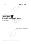
"
REACH
RoHS"
!"
ELECTRICAL OUTBOARD
X-Series
Owners Manual
Please read and retain this manual before use this electrical motor
"""""""""""""""""""""""""""""""""""""""""""""""""""""""""""""""""""""""""""""""""""""""""""""""""""""""""
!"Motor"
"
!"#$%&'(&)'*+%*+,&
!"#"$%&'(#)*$+%,(*#'
-"
./"0()(0%,(*#.'
-"
1($(#!'%#2'3%,,"$4'$"0*++"#2%,(*#.'
!"##$%&'(&)$'
+,%-.,#'/%0#$-#,01'
+"23$'4,5$'
-"
*"
*"
*"
.%)",4'(#)*$+%,(*#'
5"
)($.,',(+"'$6##(#!'
5"
+*,*$'6.%!"'
!"##$%&'+011$-#,01'6$#708'
:0;'(0'+01#%03'(7$'60#0%'
=8>.?#'(7$'=1@3$'AB':"183$'
7"
9"
<"
C"
,$%#.*+'+*6#,'(#.,%&&%,(*#'
8"
9*1',*'$"/%&0"',9"'/$*/"&&"$'
:"
2%(&4'+%(#,%(#%#0"'
:"
,$*63&"'.9**,(#!'
D0??'AB'/0;$%'
60#0%'6"G$?'HI-$??,J$'K0,?$'A%'L,2%"#,01'
60#0%'M",3?'(0'N.1'
60#0%'D0?$?'A1$'A%'60%$'4)$$8?'
;<"
EF"
EF"
EE"
EE"
1%$$%#,4'
O.%"#,01'AB'+0J$%"@$'
+018,#,01?'(7"#'6.?#'!$'6$#'P1'A%8$%'(0'A2#",1'Q"%%"1#&'+0J$%"@$'
:0;'(0'A2#",1'Q"%%"1#&'+0J$%"@$'
Q7"#'P?'K0#'+0J$%$8'
;;"
EE"
EE"
EE"
ER"
&(%3(&(,4')$""'0&%6."'
;="
"
"
#"
"""""""""""""""""""""""""""""""""""""""""""""""""""""""""""""""""""""""""""""""""""""""""""""""""""""""""
!"Motor"
-./.012&3/45061!35/&
Thank you for having our product and wish you enjoyed it.
NERAUS™ trolling motors are designed and developed by professional engineering working
teams. With years of efforts the power of NERAUS™ trolling motor has widely covered 32LBS,
36LBS, 40LBS, 46LBS, 50LBS, 55LBS and 86LBS in order to fit various costumers’
requirements and provide different experiences.
Please read and retain this manual before use this electrical motor. The manual contains
information that describes the procedure for safe operation and daily maintenance of your
electrical motor. Safe operation will prevent personal injury and product damage.
78.)343)1!35/7&
ITEMS-NO.
NRS-32X
NRS-36X
NRS-40X
NRS-46X
NRS-50X
NRS-55X
THRUST IN LBS
32
36
40
46
50
55
THRUST IN KG
14.5
16.3
18.1
20.9
22.7
25.0
INPUT
12V, 26A
12V, 29A
12V, 34A
12V, 40A
12V, 46A
12V, 52A
INPUT POWER
312W
348W
408W
480W
552W
624W
MAX SPEED*
5 KM/H
6.5 KM/H
7.8 KM/H
9.5 KM/H
12 KM/H
14.5 KM/H
* Since speed depends on many factors, such as loading, water condition and wind speed etc.,
it would be difficult to give an accurate speed rating, we give the speed for reference purposes:
Boat size, 2.3m\ Loading, 90kg\ Quiet water.
9303/-&1/:&;1!!.0<&0.)566./:1!35/7&
Battery Type
Recommended battery(s): 12-volt Deep Cycle battery or Marine battery, battery should has at
least 50-ampere hour rating or higher. To extend running time an additional battery can be used.
See section on battery connection method.
Circuit Protection
It is recommended to installing a 50 amp manual reset circuit breaker in the electric outboard
motor leads within 1.8m (72 Inches) of the battery(s).
Cable Size
If extending the standard battery cable supplied with the product NERAUS™ recommends the
use of 13mm2 wire (6-gauge wire, AWG).
"
&
&
&
" severe burns. Avoid
Batteries contain sulphuric acid, which can cause
contact with skin, eyes and clothing. The battery also produces
hydrogen and oxygen gases when being charged. This potentially
explosive mixture escapes through the fill vent cell caps and may form
an explosive atmosphere around the battery for several hours after it has
been charged. Electrical arcing or flames can ignite the gas and cause
an explosion, which may shatter the battery and could cause blindness
or other serious injury.
"
$" "
"""""""""""""""""""""""""""""""""""""""""""""""""""""""""""""""""""""""""""""""""""""""""""""""""""""""""
!"Motor"
"
&
"
Be sure all switches are in the OFF position before connecting to battery
or batteries. Electrical arcing near the battery could ignite hydrogen gas
and cause the battery to explode.
&
&
"
&
714.!<&3/45061!35/&
Do not allow children to operate the electric outboard motor.
Do not modify the unit in any way or add accessories not intended for
this product.
Never fully submerse the unit, if unit is accidentally submersed disconnect battery and leave to
dry.
"
Always disconnect power from the motor when replacing propeller,
removing debris around the prop, charging batteries, transporting boat
or when the motor is not in use.
"
To prevent accidental damage of the fiberglass shaft, do not over tighten the mounting bracket.
Only use this product between the temperatures of -20C to +45C (-4F to +113F).
User(s) should always wear approved Life Jackets.
"
4307!&!36.&0=//3/-&
1. Place Electric Outboard onto the back of the vessel in Stow away position.
2. Loosely tighten Transom Mounting Screws till they grip the Transom Mount.
3. Press the Tilt Lever and slowly let the motor enter the water.
4. Use the Depth Adjuster Collar to adjust the height of motor (Recommend running depth
150mm and 300mm below the waterline).
5. When you are satisfied that the motor is at a safe depth and isn’t too close or in danger of
hitting the bottom of the lake, river or other water ways you may proceed to tighten the Transom
Mounting Screws.
6. Once this is done it should be safe to connect the battery to the motor. Ensure that the twist
grip is in the neutral position and that the nuts are tight on the terminals to prevent a poor
connection.
"
%"
"""""""""""""""""""""""""""""""""""""""""""""""""""""""""""""""""""""""""""""""""""""""""""""""""""""""""
!"Motor"
7. Select the desired speed and direction using twist grip on the tiller arm.
8. Do not go from full forward speed to full reverse speed without letting the propeller stop
turning first or motor damage may occur.
65!50&=71-.&
The motors package does not include batteries; please choose battery with 12V (24V for
86LBS motor) output to fit this motor, the recommended type of battery is deep cycle battery
or marine battery, as they will last much longer and hard to break.
Battery Connection Method
"
Connect with one battery (DC12V)
The red wire should connect to anode; the black wire should connect to cathode.
(It is recommended install 50 amp circuit breaker in line with positive lead.)
Black cable (-ve)
from outboard
DC12
V
Red cable (+ve)
from outboard
Connect with two batteries in parallel (DC12V)
The red wire should connect to anode; the black wire should connect to cathode.
(It is recommended install 50 amp circuit breaker in line with positive lead.)
Terminal voltage output: 12V
Black cable (-ve)
from outboard
&" "
Red cable (+ve)
from outboard
"""""""""""""""""""""""""""""""""""""""""""""""""""""""""""""""""""""""""""""""""""""""""""""""""""""""""
!"Motor"
Connect with two batteries in series (DC12V)
The red wire should connect to anode; the black wire should connect to cathode.
(It is recommended install 50 amp circuit breaker in line with positive lead.)
Terminal voltage output: 24V
Black cable (-ve)
from outboard
Red cable (+ve)
from outboard
How To Control The Motor
"
Remember always disconnect from batteries once the motor leaves
water as a rotating propeller can cause personal injury.
"
On/Off Speed Control
Rotate handle clockwise to obtain any of the 5 forward speeds. Rotate handle anticlockwise for
any of the 3 reverse speeds. To stop the motor from running, position the handle following the
arrow marker and position on level 0.
Battery Level Indicator
There are 10 white LED lights on the top cover. When seven (7) LED’s are out, the meter is
indicating that the input voltage is less than 9.5V (normal voltage draw, 12V). It is advised to
disconnect the motor from the battery to prevent damage to the battery and recharge.
Adjusting Motor Depth
Position the depth adjustment collar so the propeller blades will be submerged 150mm 300mm (6inches - 12inches) below the waters surface.
"
'"
"""""""""""""""""""""""""""""""""""""""""""""""""""""""""""""""""""""""""""""""""""""""""""""""""""""""""
!"Motor"
Raising The Motor
It is recommended to disconnect the battery before carrying out this procedure to prevent
accidental running of the motor. To raise the motor out of the water push and hold the tilt lever
and with the other hand push down on the end of the handle to bring the motor up and of the
water. Then release the tilt lever to lock in place.
Lowering The Motor
It is recommended to disconnect the battery before carrying out this procedure to prevent
accidental running of the motor. Press the tilt lever while with the other hand; hold onto the end
of the handle to steady the motor into the water. Once lowered release the tilt lever to lock into
position.
"
"
Remember to wash the motor by using fresh water after used it in
salt water as it can greatly reduce the possibility of corrosions.
"
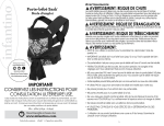
Adjust The Angle Of Handle
"
"
"
Tight adjust
button
Maritim X series motor is able to adjust the angle of handle to make comfortable for user’s
control. Please follow these steps to make adjustment.
1. Loose the button so that the handle can move upwards and downwards freely.
2. Keep the handle to the adequate angle that is suitable to control.
3. Tight the button to finish the adjustment.
"
The angle adjustment range is ± 30°, do NOT exceed this limit; force to
rotate the handle will cause the motor damage.
"
(" "
"""""""""""""""""""""""""""""""""""""""""""""""""""""""""""""""""""""""""""""""""""""""""""""""""""""""""
!"Motor"
&
&
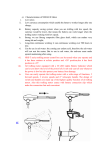
!01/756&65=/!&3/7!1221!35/&
3.
1.
2.
4.
"
Before the installation, Make sure the area between column and
bracket is clear.
"
1. Tilt Position Lever - The lever allows the user to adjust the tilt (angle) of the motor. Push tilt
position lever, adjust tilt of motor, release lever.
2. Steering Tension Adjustment -To adjust the steering resistance, simply tighten or loosen the
tension knob located on front of the mount.
3. Depth Adjustment Collar -The depth of the motor can be adjusted up and down by loosening
the depth collar tension knob located on the column directly above the mount. The column can
be adjusted and the motor can be positioned at the desired depth by retightening the tension
knob.
4. Transom Screws -The transom clamp screws allow for easy motor removal and installation.
Mount your motor on the transom then tighten the transom clamp screws securely.
"
The motor can only be used in water that deeper than 0.7m.
"
"
)"
"""""""""""""""""""""""""""""""""""""""""""""""""""""""""""""""""""""""""""""""""""""""""""""""""""""""""
!"Motor"
&
&
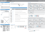
>59&!5&0.812).&!>.&8058.22.0&
"
"
"
Make sure that the motor has been disconnected from batteries.
"
Hold the propeller blade and loosen the propeller nut using the prop spanner supplied or a set of
needle nose pliers. Remove the propeller nut. Pull the propeller straight off. If prop is stuck,
grasp one blade with one hand and tap on the backside of the opposite blade lightly with a
rubber mallet, until the propeller comes off. If the propeller pin is bent, replace it. Align the new
propeller with the propeller pin. Reinstall the propeller nut and tighten firmly by hand, tighten with
spanner another 1/4 turn.
"
"
"
Step 1
Step 2
Step 3
"
"
Do not strike bent prop pin with hammer to remove pin. Damage to
motor armature may occur that would not be covered by warranty."
:132<&613/!13/1/).&
1. Check behind the propeller after each day for weeds, fishing line or other debris that may get
wrapped behind the propeller.
2. Lubricate all the pivot points with a non-aerosol lubricant. Never use aerosol lubricants to
grease or oil any part of the unit. Many spray lubricants contain harmful propellants that can
cause damage to various parts of your fishing motor.
3. Check tightness of the battery lead connections.
4. Visually check condition of main battery cables.
*" "
"""""""""""""""""""""""""""""""""""""""""""""""""""""""""""""""""""""""""""""""""""""""""""""""""""""""""
!"Motor"
5. Inspect for loose or corroded wiring connections.
6. Always thoroughly rinse your electric outboard motor with fresh water after every use in salt
water. Only rinse the areas that have been in contact with salt water, avoid getting the top cover
wet as this may damage the circuitry inside.
7. Make visuals inspections for tightness of all nuts, bolts and screws.
8. Recharge batteries after each use. Follow the battery manufacture’s recommendations for
battery maintenance.
9. During freezing temperatures, when your electric motor is not being used, it should be stored
in an area where it will not freeze.
10. Never connect the wire with wrong electrode. Must disconnect with battery during
maintenance.
!05=;2.&7>55!3/-&
"
Loss Of Power
"
Propeller may be fouled. Remove propeller, clean and replace.
Battery connections may be corroded.
Battery has low voltage. Recharge.
Battery may be faulty, recharge and check.
Insufficient cable size from battery to motor wiring, 13mm2 thickness / 6 gauge wire (AWG)
recommended.
Bad or faulty connection in boat wiring or electric motor wiring
Permanent magnet cracked or chipped. Motor will whine or grind.
Motor Makes Excessive Noise Or Vibration
"
Propeller may be fouled.
Propeller by be damaged or unbalanced.
Check to see if propeller is secured.
Bent armature. Remove propeller, set at medium speed, turn unit on and watch armature
wobble.
Turn propeller by hand. It should turn freely with a slight magnetic drag.
Bearing\bushes may be worn out.
"
+,"
"""""""""""""""""""""""""""""""""""""""""""""""""""""""""""""""""""""""""""""""""""""""""""""""""""""""""
!"Motor"
Motor Fails To Run
"
Check fuse\circuit breaker on boat for electric motor.
Check for loose or corroded connections.
Check plug for loose or bad connection.
Test main rotary switch.
Turn prop by hand. It should turn freely with a slight magnetic drag.
Total battery failure. Recharge and check voltage.
Propeller Fouled.
Motor Loses One Or More Speeds
"
Lose wire on rotary switch. Check wiring diagram.
Lose connection in top housing.
Rotary switch damaged.
Speed coils in lower unit may be burned.
91001/!<&
Duration Of Coverage
This Limited Warranty provides coverage for two (2) years from the date the product is first
manufactured from factory. Therefore the ultimate purchaser may have limited warranty
coverage period for less than two (2) years due to the time of transferring, sale and storage. The
only reference for duration of warrant coverage is the serial No., which is imprinted on the
surface of motor’s transom mount. The repair or replacement of parts, or the performance of
service under this warranty, does not extend the life of this warranty beyond its original expiry
date.
Conditions That Must Be Met In Order To Obtain Warranty
Coverage
Warranty coverage is only available from an authorized dealer to distribute the product in the
country in which the sale occurred. Routine maintenance out-lined in the Operation and
Maintenance section must be performed in order to maintain warranty coverage. If the retail
customer performs maintenance, NERAUS™ reserves the right to make future warranty
coverage possible only with proof of proper maintenance.
How To Obtain Warranty Coverage
Delivering the product to an authorized dealer for inspection should make warranty claims; proof
of purchase will be required to receive warranty.
The dealer will then arrange for the inspection and any necessary repair. The purchaser in that
case shall pay for all related transport charges and/or travel time. If the service provided is not
covered by the warranty, purchaser shall pay for all related labor and material, and any other
expenses associated with that service.
++" "
"""""""""""""""""""""""""""""""""""""""""""""""""""""""""""""""""""""""""""""""""""""""""""""""""""""""""
!"Motor"
What Is Not Covered
This limited warranty does not cover routine maintenance items, adjustments, normal wear and
tear, damage caused by abuse, abnormal use, operation of the product in a manner
inconsistent with the recommended operation/duty cycle section of the Operation and
Maintenance Manual, neglect, accident, submersion, improper installation (proper installation
specification and techniques are set forth in the Operations and First time running sections in
this manual), improper service, use of an accessory or part not manufactured or sold by us, or
alteration or removal of parts. Expenses related to haul-out, launch, towing, storage, telephone,
rental, inconvenience, slip fees, insurance coverage, loan payments, loss of time, loss of income,
or any other types of accidental or consequential damages are not covered by this warranty.
Check the following chart to see what parts are in warrant coverage.
Motor Rotor
Motor Magnet
Speed Switch
Carbon Brush Holder
Propeller
Screw
Telescoping Handle
10 Points Battery Meter
Plastic Control Box
Electrical Wire
Sticker
Rubber Band
Other Electrical Parts
Other Metal Parts
Free Replace within 2 Years, By sea, distributor must keep faulty part
for inspection
Free Replace within 2 Years, By sea, distributor must keep faulty part
for inspection
Free Replace within 1 Year, By sea, distributor must keep faulty part
for inspection
Free Replace within 1 Year, By sea, distributor must keep faulty part
for inspection
Not available, the end-user should pay for it.
Not available, the end-user should pay for it.
Free Replace within 1 Year, By sea, distributor must keep faulty part
for inspection
Free Replace within 1 Year, By sea, distributor must keep faulty part
for inspection
Free Replace within 1 Year, By sea, distributor must keep faulty part
for inspection
Free Replace within 1 Year, By sea, distributor must keep faulty part
for inspection
Not available, the end-user should pay for it.
Not available, the end-user should pay for it.
Free Replace within 1 Year, By sea, distributor must keep faulty part
for inspection
Free Replace within 1 Year, By sea, distributor must keep faulty part
for inspection
"
231;323!<&40..&)21=7.&
The damage caused by falling down, crash, cut, pierce or other man-made behaviors;"
The end-user did not follow the instruction manual;
The end-user ignored our warning information;
Placed or changed the motors under wet circumstance may damage the batteries, the circuit or
other electric parts.
Used the parts or accessories that are not from us"
"
"
+#"
!!!!!!!!!!!!!!!!!!!!!!!!!!!!!!!!!!!!!!!!!!!!!!!!!!!!!!!!!!!!!!!!!!!!!!!!!!!!!!!!!!!!!!!!!!!!!!!!!!!!!!!!!
"!Motor!
Declaration of Conformity for Recreational Craft
Propulsion Engine with the requirements of Directive
89/392/EEC as amended by 89/336/EEC.
Name of Engine manufacturer: Neraus Sports & Leisure Article Company Ltd,
Address: No. 1888 TongTu Road, Ningbo, China
Engine type approved according to: Directives 89/392/EEC, 89/336/EE
Description of Engine(s) and Essential Requirements
Engine Type: Outboard Engine
Fuel Type: Electric
This declaration of conformity is issued under the sole responsibility of the manufacturer. I declare on behalf
of the manufacturer that the motor(s) is (are) in conformity with the type(s) for which above mentioned EC,
EMC and ROHC type-examination or type approval certificate(s) has (have) been issued and it will meet the
requirements of Directive 89/392/EEC, 89/336/EEC as amended when installed in a recreational craft, in
accordance with the manufacturer’s supplied instructions
!
!
!
#$!