1
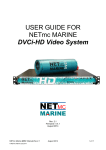
RJE INTERNATIONAL, INC.
ATT-400 SERIES
ACOUSTIC TARGET
TRANSPONDER
USER MANUAL
REV 1.5
5/15/2015
Forward
This manual is comprised of figures and text intended to provide descriptions and
instructions for the deployment, operation, and maintenance of the RJE
International ATT-400 Series Acoustic Target Transponder. The information herein
is arranged into chapters and sections as follows:
Chapter 1 – An overview of the ATT-400. General notes including brief sections
describing the applications and physical characteristics of the Beacon itself.
Chapter 2 – Specifications. Sections comprised of lists of both general and uniqueto-the-unit specifications.
Chapter 3 – Operation and Deployment Notes. Sections detail the unpacking and
predeployment checkout procedures for the ATT-400.
Chapter 4 - Maintenance. Sections detail periodic maintenance, battery replacement
and calibration procedures.
Please forward comments, questions, suggestions, or problems with the text,
figures, or equipment to RJE International.
ii
RJE International, Inc.
15375 Barranca Parkway, Suite B107, Irvine, CA 92618
Tel: (949)727-9399 Fax: (949)727-0070
E-mail: [email protected] Web Page: www.rjeint.com
PROPRIETARY MATERIAL
The descriptions, procedural information, photos, figures, drawings, illustrations, in this manual are the
property of RJE International, Inc. Materials may not be reproduced or disseminated without the prior
written consent of RJE International.
RJE International reserves the right to make changes in design or specifications at any time without
incurring any obligation to modify previously installed units.
This manual is provided for information and reference purposes only and is subject to change without
notice.
LIMITED WARRANTY
RJE International, Inc. (RJE) guarantees its products to be free from defects in materials and
workmanship for a period of one year from the date of shipment. In the event a product
malfunctions during this period, RJE’s obligation is limited to the repair or replacement, at RJE’s
option, of any product returned to the RJE factory. Products found defective should be returned to
the factory freight prepaid and carefully packed, as the customer will be responsible for any damage
during shipment.
Repairs or replacements, parts, labor, and return shipment under this warranty will be at no cost to
the customer. This warranty is void if, in RJE’s opinion, the product has been damaged by accident or
mishandled, altered, or repaired by the customer, where such treatment has affected its
performance or reliability. In the event of such mishandling, all costs for repair and return freight will
be charged to the customer. All products supplied by RJE that are designed for use under hydrostatic
loading have been certified by actual pressure testing prior to shipment. Any damage that occurs as
a direct result of flooding is NOT covered by this warranty.
If a product is returned for warranty repair and no defect is found, the customer will be charged a
diagnostic fee plus all shipping costs. Incidental or consequential damages or costs incurred as a
result of a product’s malfunction are not the responsibility of RJE.
All returned products must be accompanied by a CASE number issued by RJE International. Shipments
without a CASE number will not be accepted.
LIABILITY
RJE shall not be liable for incidental or consequential damages, injuries, or losses as a result of the
installation, testing, operation, or servicing of RJE products.
iii
RJE International, Inc.
15375 Barranca Parkway, Suite B107, Irvine, CA 92618
Tel: (949)727-9399 Fax: (949)727-0070
E-mail: [email protected] Web Page: www.rjeint.com
RETURN PROCEDURE
Before returning any equipment to RJE, you must contact RJE and obtain a Case number. The Case
number assists RJE in identifying the origin and tracking the location of returned items.
When returning items to RJE from outside the United States, follow the checklist presented below
to prevent any delays or additional costs.
Include with all shipments two copies of your commercial invoice showing the value of the
items and the reason you are returning them. Whenever possible, send copies of the
original export shipping documents with the consignment.
Route via courier (FedEx or UPS).
If there is more than one item per consignment, include a packing list with the shipment. It is
acceptable to combine the commercial invoice and packing list with the contents of each
carton clearly numbered and identified on the commercial invoice.
If it is necessary to ship via airfreight, contact RJE for specific freight forwarding instructions.
You will be charged for customs clearance and inbound freight.
Insure the items for their full value.
Refer to the RJE issued Case number on all documents and correspondence.
Prepay the freight.
TITLE
Title shall pass to buyer on delivery to carrier at Irvine, CA. Risk of damage or loss following such delivery
shall be to the buyer and RJE International shall in no way be responsible for safe arrival of the shipment.
Title shall so pass to buyer regardless of any provision for payment of freight or insurance by RJE
International or of the form of shipping documents. If shipment is consigned to RJE International, it shall
be for the purpose of securing buyer’s obligations under the contract.
iv
RJE International, Inc.
15375 Barranca Parkway, Suite B107, Irvine, CA 92618
Tel: (949)727-9399 Fax: (949)727-0070
E-mail: [email protected] Web Page: www.rjeint.com
THIS PAGE IS INTENTIONALLY LEFT BLANK
v
RJE International, Inc.
15375 Barranca Parkway, Suite B107, Irvine, CA 92618
Tel: (949)727-9399 Fax: (949)727-0070
E-mail: [email protected] Web Page: www.rjeint.com
TABLE OF CONTENTS
FORWARD
WARRANTY
1 – Introduction to the ATT-400 Acoustic Target Transponder
1.1 Overall Description ........................................................................................................ 1
1.2 ATT-400 Series Acoustic Target Transponder............................................................... 1
2 – ATT-400 Specifications
2.1 ATT-400 Acoustic Target Transponder Specifications................................................... 3
2.2 ATT-400EXT External Power Transponder Specifications ............................................ 4
2.3 ATT-400IK-SW/WTO External Activation Transponder Specifications .......................... 5
3 – Operations & Installation Notes
3.1 Introduction .................................................................................................................... 5
3.2 Unpacking...................................................................................................................... 5
3.3 Setting the ATT-400 Transmit Frequency Selector Rotary Switch ................................. 6
4 – ATT-400 Maintenance
4.1 Maintenance .................................................................................................................. 8
4.2 Replacing the ATT-400 Battery...................................................................................... 8
ILLUSTRATIONS
FIGURE 1-1 Model DTI-300A Diver Transponder Interrogator ............................................ 1
FIGURE 1-2 Model VADR-1000M Vehicle Acoustic Receiver ............................................. 1
FIGURE 1-3 Model ATT-400 Acoustic Target Transponder ................................................ 2
FIGURE 1-4 Model ATT-400EL Acoustic Target Transponder ............................................ 2
FIGURE 1-5 Model ATT-400/1KM and ATT-400/6KM Transponder, Deep-water ............... 2
FIGURE 1-6 Model ATT-400EXT Transponder External Power .......................................... 2
FIGURE 2-1 Model ATT-400EXT Connection Detail ........................................................... 4
FIGURE 2-2 Model ATT-400IK-SW/WTO Connection Detail ............................................... 4
FIGURE 3-1 ATT-400 Disassembly ..................................................................................... 6
FIGURE 3-2 Channel Selector Switch ................................................................................. 6
FIGURE 4-1 ATT-400 Disassembly ..................................................................................... 8
FIGURE 4-2 ATT-400 Battery Connections ......................................................................... 9
FIGURE 4-3 ATT-400 Battery Installation............................................................................ 9
TABLES
TABLES 2-1 ATT-400 Specifications ................................................................................... 2
vi
RJE International, Inc.
15375 Barranca Parkway, Suite B107, Irvine, CA 92618
Tel: (949)727-9399 Fax: (949)727-0070
E-mail: [email protected] Web Page: www.rjeint.com
TABLES 2-2 ATT-400EXT Specifications ............................................................................ 4
TABLES 3-1 Channel Select Switch Settings ...................................................................... 7
vii
RJE International, Inc.
15375 Barranca Parkway, Suite B107, Irvine, CA 92618
Tel: (949)727-9399 Fax: (949)727-0070
E-mail: [email protected] Web Page: www.rjeint.com
Section
1
1.1
Overall Description
The RJE International ATT-400 Series Acoustic Target Transponder is an underwater acoustic
signaling device that works with transponder interrogators for diver marking and relocation. In
addition the ATT-400 Series Transponder can be configured to operate as a free running pinger
with eight user selectable operating frequencies.
Figure 1-2
VDAR-1000M Vehicle
Acoustic Receiver
Figure 1-1
DTI-300A Diver Transponder
Interrogator
1.2
ATT-400 Series Acoustic Target Transponder
The ATT-400 series transponders are small battery operated underwater acoustic devices
that works with the DTI-300A and STI-350 transponder interrogators or SEEKER series
subsea vehicle acoustic receivers to mark and relocate targets underwater in ranges of 750
meters (2461ft). The ATT-400 comes in six models, ATT-400 standard, ATT-400EL long life,
ATT-400/1KM, ATT-400/6KM deep-water models, ATT-400EXT external power model and
ATT-400IK-SW/WTO externally activated. Once deployed, a water switch actives the
transponder where it can remain in the receive mode for up to 18 months waiting quietly
for an interrogation signal from a transponder interrogator. Once interrogated, the ATT-400
transponder responds to the interrogator using eight different user programmable
channels.
1
RJE International, Inc.
Tel: (949)727-9399 Fax: (949)727-0070, E-mail: [email protected] Web Page: www.rjeint.com
The ATT-400 series transponder can also be operated as a free running pinger by
changing the setting on the PCB as shown in section 3.3 of this manual. By selecting
this option, the ATT-400 sends an acoustic signal continuous with eight user
selectable channels.
In addition, the ATT-400 series transponder is positively buoyant and requires no
additional flotation so deployment is easy. Constructed of non-corrosive material, the
ATT-400 transponders can be deployed to depth from 100 meters to 6000 meters.
Figure 1-4
ATT-400EL Long Life Transponder
Figure 1-5
ATT-400/1KM and ATT-400/6KM
Transponder, Deep-Water
Figure 1-3
ATT-400 Transponder
Figure 1-6
ATT-400EXT Transponder External
Power
2
RJE International, Inc.
Tel: (949)727-9399 Fax: (949)727-0070, E-mail: [email protected] Web Page: www.rjeint.com
Section
2
2.1
ATT-400 Acoustic Target Transponders Specifications
Table 2-1 ATT-400 Series Acoustic Transponder Specifications
Receive Frequency
26 kHz
Acoustic Source Level
180 dB re 1µPa @ 1 meter
Transmit Repetition Rate
Normal: 1.0 second
Transmit Pulse Length
5.0 ms
Transmit Frequency
Switch-selectable to 27, 28, 29, 30, 31, 32, 33, 34 kHz
Transponder Turnaround Time
Compensation
20 ms
Activation
Water Activated Switch
Battery
9 Volt Battery QTY 2
Range
750m (2461ft) with DTI-300, STI-350, or VADR Receivers
Operating Life
ATT-400, ATT-400/1KM, ATT-400/6KM: 6 Months Stand by or
360,000 Replies in Transponder Mode. 4 Days in Pinger Mode
ATT-400EL: 18 Months Stand by or 1,000,000 Replies in
Transponder Mode. 12 Days in Pinger Mode
Operational Depth
100m (328ft)
Housing Material
ATT-400, ATT-400EL: Delrin and glass-filled polycarbonate; Oring sealed
ATT-400/1KM, ATT-400/6KM: Anodized Aluminum; O-ring
sealed
Dimensions
ATT-400, ATT-400/1KM, ATT-400/6KM: 23cm x 6.4cm
2.5in )
ATT-400EL: 30cm x 6.4cm
Weight
(9.0in x
(12.0in x 2.5in )
ATT-400: In Air: 0.75lbs (0.34kg) In Water: Positively Buoyant
ATT-400EL: In Air: 1.4lbs (0.63kg), In Water: Positively Buoyant
ATT-400/1KM, ATT-400/6KM: In Air 3.85lbs (1.1kg):
In Water: 2.36lbs (1.1kg)
Specifications are subject to change
3
RJE International, Inc.
Tel: (949)727-9399 Fax: (949)727-0070, E-mail: [email protected] Web Page: www.rjeint.com
2.2
SPECIFICATIONS UNIQUE TO THE ATT-400EXT
Table 2-2 ATT-400EXT External Power Transponder Specifications
External Power Requirements
18-36VDC(24VDC Nominal) @ 2Amps
Connector
Range
Subconn MCIL2F with 6m mating cable assembly with locking
sleeve.
750m (2250ft) with DTI-300, STI-350, or VADR Receivers
Operational Depth
100m (328ft)
Housing Material
Delrin and glass-filled polycarbonate; O-ring sealed
Dimensions
23cm x 6.4cm
Weight
In Air: 0.45Kg (1 lbs.), In Water: Positively Buoyant
(9.0in x 2.5in )
The ATT-400EXT functions the same as the ATT-400 Target Transponder except the unit is
externally powered form a secondary source. All other functions are the same.
1
2
Guide
Pin
Figure 2-1 Connection Detail
ATT-400 End cap with face
view of SubConn Male
connector part number
MCIL2F.
Pin 1 +24VDC
Pin 2 – Common
4
RJE International, Inc.
Tel: (949)727-9399 Fax: (949)727-0070, E-mail: [email protected] Web Page: www.rjeint.com
2.3
SPECIFICATIONS UNIQUE TO THE ATT-400IK-SW/WTO
Table 2-3 ATT-400IK-SW/WTO Power Loss Transponder Specifications
Range
Subconn MCIL2F with .6m(24in) mating cable assembly with
locking sleeve.
750m (2250ft) with DTI-300, STI-350, or VADR Receivers
Operational Depth
1000m (3280ft)
Housing Material
T6 Anodized Aluminum; O-ring sealed
Dimensions
23cm x 6.4cm
Weight
In Air: 0.82Kg (1.83 lbs.), In Water: Positively Buoyant
Connector
(9.0in x 2.5in )
The ATT-400IK-SW/SWO functions the same as the ATT-400 Target Transponder except the unit
is externally activated. All other functions are the same.
1
2
Guide
Pin
Figure 2-2 Connection Detail ATT-400
End cap with face view of SubConn
Male connector part number MCIL2F.
When unit is submerged short pin 1 and pin 2 together to activate the unit
5
RJE International, Inc.
Tel: (949)727-9399 Fax: (949)727-0070, E-mail: [email protected] Web Page: www.rjeint.com
Section
3
OPERATIONS & INSTALLATION NOTES
3.1
Introduction
The ATT-400 Series Acoustic Target Transponder is a small self-contained acoustic device
that can operate as a transponder or a free running pinger. Using a water switch, the ATT400 activates once it is placed in the water and shuts down when removed for the water. It
operates in both fresh and salt-water environments.
A Rotary-switch on the board allows the operator to select what mode to place the ATT-400
in (transponder or free-running pinger) and to select which of the eight different
frequencies (from 27khz to 34khz) to transmit in.
If set up in the transponder mode the ATT-400 will remain activated from up to six to
eighteen months, based on model, while it waits to receive a coded interrogation signal
from a transponder interrogator. In the free-running pinger mode, the ATT-400 will
activated once immersed and continuously send a signal from 4 to 12 days, based on model.
Because it can be programmed to operate on eight different channels, the operator can
mark and relocate eight different locations simultaneously.
3.2
Unpacking
When opening the shipping cartons, carefully inspect each piece of equipment, as it is
unpacked, and report any damage to the freight carrier and to RJE International.
As with any sophisticated electronic equipment, RJE International products should be
handled with a reasonable amount of care during unpacking, transporting and storing. Pay
particular attention to make sure that:
• The end caps are properly secured and the end cap screws are tightened.
• There is no damage to the housing.
6
RJE International, Inc.
Tel: (949)727-9399 Fax: (949)727-0070, E-mail: [email protected] Web Page: www.rjeint.com
3.3
Setting the ATT-400 Transmit Frequency Using the Rotary
Switch
•
Loosen and remove the knurled locking collar from the housing and gently
remove the end cap.
Figure 3-1 ATT-400 Disassemble
•
Orient the ATT-400 assembly so the rotary switch is locate as shown below.
Figure 3-2 Channel Select Switch
7
RJE International, Inc.
Tel: (949)727-9399 Fax: (949)727-0070, E-mail: [email protected] Web Page: www.rjeint.com
•
Set the switch positions of SW1 to the position for the desired channel and/or
frequency (Table 3-1).
Table 3-1 Channel Select Switch Settings
Mode
Transponder
Transponder
Transponder
Transponder
Transponder
Transponder
Transponder
Transponder
Pinger
Pinger
Pinger
Pinger
Pinger
Pinger
Pinger
Pinger
SW
CH#/Frequency
Selection
0
CH1/27kHz
1
CH2/28kHz
2
CH3/29kHz
3
CH4/30kHz
4
CH5/31kHz
5
CH6/32kHz
6
CH7/33kHz
7
CH8/34kHz
8
27kHz
9
28kHz
A
29kHz
B
30kHz
C
31kHz
D
32kHz
E
33kHz
F
34kHz
8
RJE International, Inc.
Tel: (949)727-9399 Fax: (949)727-0070, E-mail: [email protected] Web Page: www.rjeint.com
Section
4
ATT-400 MAINTENANCE
4.1
Maintenance
Upon completion of each dive mission, take these steps to assure continued reliable
performance from the ATT-400 transponders.
•
Wash the exterior of the equipment with fresh water and mild detergent.
Pay particular attention to cleaning film build-up from the transducer face.
•
Make sure the equipment has been thoroughly dried before storage.
•
Inspect all system components for damage and wear.
replacement parts if required.
4.2
Order needed
Replacing the ATT-400 batteries
The batteries in the ATT-400 transponder should be replaced after six to 10 months,
based on model, or prior to each use. To change the ATT-400 batteries follow this
procedure:
•
Gently loosen and remove the end cap assembly from the housing by turning
counter clockwise.
Figure 4-1 ATT-400 Disassembly
•
Remove the old batteries (two or six based on model) and install the new
battery as shown. Note the battery terminal orientation before making
connection. Insure the battery terminals are fully seated.
9
RJE International, Inc.
Tel: (949)727-9399 Fax: (949)727-0070, E-mail: [email protected] Web Page: www.rjeint.com
Figure 4-2 ATT-400 Battery Connections
•
Rotate the transponder assembly and repeat the same steps for the opposite
side. When completed the assembly will look as shown.
Figure 4-3 ATT-400 Battery Installation
•
Before installing the end cap assembly, make sure the O-ring and O-ring surfaces
are clean and free of debris. Lubricate the O-ring with a light coat of silicon grease
(O-lube) supplied in the spares kit.
•
Reassemble the unit by reversing the order of disassembly.
10
RJE International, Inc.
Tel: (949)727-9399 Fax: (949)727-0070, E-mail: [email protected] Web Page: www.rjeint.com