1
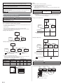
Checking gas leaks with vacuum:
5.3. Connecting the piping
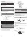
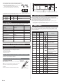
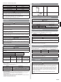
BENDING PIPES
(1) When bending the pipe, be careful not to crush it.
(2) To prevent breaking of the pipe, avoid sharp
Check if [L] is Àared uniformly and
is not cracked or scratched.
bends.
Bend the pipe with a radius of curvature of
150 mm or over.
(3) If the copper pipe is bend the pipe or pulled
to often, it will become stiff. Do not bend the
pipes more than three times at one place.
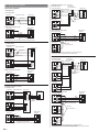
FLARING
(1) Cut the connection pipe to the necessary
length with a pipe cutter.
Die
(2) Hold the pipe downward so that cuttings will
not enter the pipe and remove the burrs.
A
(3) Insert the flare nut onto the pipe and flare
the pipe with a Àaring tool.
Pipe
Insert the flare nut (always use the flare nut
attached to the indoor and outdoor units respectively) onto the pipe and perform the Àare
processing with a Àare tool.
Use the special R410A Àare tool, or the conventional (for R22) Àare tool.
When using the conventional Àare tool, always use an allowance adjustment gauge and
secure the A dimension shown in Table 2.
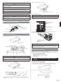
CONNECTION
(1) Install the outdoor unit wall cap (supplied with the optional installation set or procured at the site) to the wall pipe.
(2) Connect the outdoor unit and indoor unit piping.
(3) After matching the center of the Àare surface and tightening the nut hand tight,
tighten the nut to the speci¿ed tightening torque with a torque wrench. (Table 1)
Tighten with two wrenches.
Wrench (¿xed)
Flare nut
Torque
wrench
Indoor unit pipe
Table 1
Connection pipe
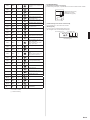
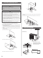
Checking gas leaks with nitrogen gas:
(1) Check if the piping connections are secure.
(2) Remove the cap of 3-way valve, and connect the gauge manifold charge hoses to
the charging port of the 3-way valve.
(3) Pressurize with nitrogen gas using the 3-way valve charging port.
(4) Do not pressurize up to the speci¿ed pressure all at once but do so gradually.
1 Increase the pressure up to 0.5 MPa (5 kgf/cm2), let it sit for about ¿ve minutes
and then check for any decrease in pressure.
2 Increase the pressure up to 1.5 MPa (15 kgf/cm2), let it sit for about ¿ve minutes
and then check for any decrease in pressure.
3 Increase the pressure up to the speci¿ed pressure (the pressure designed for the
product) and then make a note of it.
(5) Let it sit at the speci¿ed pressure and if there is no decrease in pressure then it is
satisfactory. If a pressure decrease is con¿rmed, there is a leak, so it is necessary to
specify the leak location and make minor adjustments.
(6) Discharge the nitrogen gas and starting removing the gas with a vacuum pump.
(7) Open the valve of the gauge manifold fully.
(8) Operate the vacuum pump and start pump down.
(9) Check that the compound pressure gauge reads -0.1 MPa (76 cmHg), operate the
vacuum pump for at least 1 hour.
(10) At the end of pump down, close the valve of the gauge manifold fully and stop the
vacuum pump.
(11) Disconnect the charge hose from the 3-way valve charging port.
(12) Remove the blank caps, and fully open the spindles of the 2-way and 3-way valves
with a hexagon wrench.
[torque: 6 to 7 N·m (60 to 70 kgf·cm)].
(13) Tighten the blank caps and charging port cap of the 2-way valve and 3-way valve to
the speci¿ed torque.
Flare nut size and tightening torque
Flare nut [mm (in.)]
6.35 (1/4) dia.
9.52 (3/8) dia.
12.70 (1/2) dia.
15.88 (5/8) dia.
19.05 (3/4) dia.
Table 2
To prevent gas leakage, coat the Àare
surface with refrigerator oil.
(1) Check if the piping connections are secure.
(2) Remove the cap of 3-way valve, and connect the gauge manifold charge hoses to the
charging port of the 3-way valve.
(3) Open the valve of the gauge manifold fully.
(4) Operate the vacuum pump and start pump down.
(5) Check that the compound pressure gauge reads -0.1 MPa (76 cmHg), operate the
vacuum pump for at least 1 hour.
(6) At the end of pump down, close the valve of the gauge manifold fully and stop the
vacuum pump.
(It checks that leave as it is for about 10 minutes, and a needle does not return.)
(7) Disconnect the charge hose from the 3-way valve charging port.
(8) Remove the blank caps, and fully open the spindles of the 2-way and 3-way valves
with a hexagon wrench.
[torque: 6 to 7 N·m (60 to 70 kgf·cm)].
(9) Tighten the blank caps and charging port cap of the 2-way valve and 3-way valve to
the speci¿ed torque.
Tightening torque [N•m (kgf•cm)]
16 to 18 (160 to 180)
32 to 42 (320 to 420)
49 to 61 (490 to 610)
63 to 75 (630 to 750)
90 to 110 (900 to 1100)
3-way valve
Pipe outside diameter
Pipe outside diameter
[mm (in.)]
Gauge manifold
Compound pressure gauge
Pressure gauge
-0.1 MPa
2-way valve
(-76 cmHg
Flare nut
-1 bar)
High
Low pressure
pressure
side valve
side valve
(closed)
Dimension A [mm]
Flare tool for R410A, clutch type
Valve stem
Blank cap
6.35 (1/4)
9.52 (3/8)
12.70 (1/2)
15.88 (5/8)
19.05 (3/4)
Charge
hose
Charge hose
0 to 0.5
Charging port
Charging port cap
Vacuum pump
Tightening torque
CAUTION
Fasten a Àare nut with a torque wrench as instructed in this manual. If fastened too
tight, the Àare nut may be broken after a long period of time and cause a leakage of
refrigerant.
During installation, make sure that the refrigerant pipe is attached ¿rmly before you run
the compressor. Do not operate the compressor under the condition of refrigerant piping
not attached properly with 2-way or 3-way valve open. This may cause abnormal pressure in the refrigeration cycle that leads to breakage and even injury.
5.4. Air purge
Always use a vacuum pump to purge the air.
Refrigerant for purging the air is not charged in the outdoor unit at the factory.
Close the high pressure side valve of the gauge manifold fully and do not operate it during
the following work.
CAUTION
Refrigerant must not be discharged into atmosphere.
After connecting the piping, check the joints for gas leakage with gas leak detector.
Gas leak checks are performed using either vacuum or nitrogen gas, so select the proper
one depending on the situation.
En-5
6.35 mm (1/4 in)
Blank cap
20 to 25 N·m (200 to 250 kgf·cm)
9.52 mm (3/8 in.)
20 to 25 N·m (200 to 250 kgf·cm)
12.70 mm (1/2 in.)
28 to 32 N·m (280 to 320 kgf·cm)
15.88 mm (5/8 in.)
30 to 35 N·m (300 to 350 kgf·cm)
19.05 mm (3/4 in.)
Charging port cap
35 to 40 N·m (350 to 400 kgf·cm)
12.5 to 16 N·m (125 to 160 kgf·cm)