1
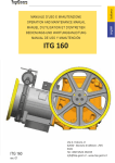
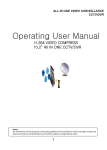
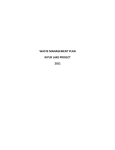
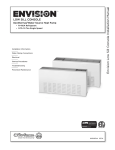
Installation Instructions
Part Number: 0001-1019
1100 Degasser Retrofit Kit.
Europe / Global Headquarter
North America
Japan
Biotech AB.
Biotech USA LLC.
BioNik Inc.
Telephone +46 (0)300-56 91 80.
Telephone +01 (0)612-703-5718.
Telephone +81-545-38-9125.
[email protected]
[email protected]
[email protected]
dĂďůĞŽĨŽŶƚĞŶƚƐ͗
Introduction ……………………………………….........1
Getting Started …………………………….…….........1
Safety Warnings ………………………………….........1
Removing Original Components …………….…..2
Installing Biotech Kit Components ……………..3
Finish ……………………….………………...……..........4
Technical Support .…………………..………...….....4
Shutdown..…………………..………………...….........5
/ŶƚƌŽĚƵĐƚŝŽŶ͗
This manual covers the Installation of the Biotech Degasser Retrofit Kit for the
Model 1100 Degasser. This kit is a drop in replacement for the original 1100
internal components that is based on Teflon® AF membrane technology and closed
loop vacuum control. The original power supply, control board and pressure sensor
are retained so that communication with the instrument stack and software is
maintained. The following procedures should only be performed by a qualified technician.
'ĞƚƚŝŶŐ^ƚĂƌƚĞĚ͗
Kit Components:
Qty 1: PN 9000-0002, Degassing Tray Assy.
Qty 1: PN 9000-0001, Power Cable Assy.
Qty 1: PN 8000-0032, Sensor Mounting Bracket.
Equipment Required:
Model 1100 User Manual, for cover removal and reinstallation instructions.
# 1 Phillips Screwdriver.
^ĂĨĞƚLJtĂƌŶŝŶŐƐ͗
!
Warning:
The original vacuum chamber membranes should be flushed to remove any
potentially hazardous solvents that may be remaining. Protective gloves and
face protection should be worn and the operation performed in a properly
ventilated area. Consult your company’s Safety Director for more information.
Make sure that the power cord is unplugged from the unit before
proceeding!
Page 1
ZĞŵŽǀŝŶŐKƌŝŐŝŶĂůŽŵƉŽŶĞŶƚƐ͗
1: Remove the outer cover and top plate, refer to the 1100 Operators Manual.
(See Appendix A for these instructions if the manual is not available.)
2: Disconnect the tube running from the sensor from the chamber port, leaving the
tube connected to the port on the sensor. Remove the screw holding the small
bracket holding the sensor PC board from the post on the drip tray and set the
sensor assy behind the drip tray. You do not need to disconnect the cable from
the Control Board.
3: Remove the screws holding the Vacuum Chamber, Vacuum Pump, and the
Vacuum Valve. Disconnect the cables for the pump and valve from the control
board. These items can be discarded but retain the screws that were securing
these for future use (Qty 2: M3 x 6 and Qty 2: M3 x 16 will be needed).
4: Loosen the two screws securing the cover over the power supply and control
board a few turns and remove this cover.
Unit after original components removed.
Page 2
/ŶƐƚĂůůŝŶŐŝŽƚĞĐŚ<ŝƚŽŵƉŽŶĞŶƚƐ͗
1: Install the new Degasser Tray assy., slide the bulkheads through the openings
in the front panel and set in position.
2: Secure the new tray using 1 M3 x 6 and 2: M3 x 16 screws saved earlier.
M3 x 16
M3 x 6
3: Slide the original sensor PC board assy., into the sensor mounting bracket, as
shown with the mounting hole relief facing up and the solder side of the sensor
board facing up, until sensor locks in place. Note: when sliding the assembly in
place be careful to support the sensor by holding the sensor with your index
finger on one side with your thumb on the backside of the board to prevent
breaking the bond between the sensor and PC board.
4: Secure the Sensor Bracket to the post on the drip tray that it was removed from
earlier using an M3 x 6 screw saved earlier.
5: Connect the tube from the sensor to the TEE on the Degasser Tray Assy.
Page 3
/ŶƐƚĂůůŝŶŐŝŽƚĞĐŚ<ŝƚŽŵƉŽŶĞŶƚƐŽŶƚ͗
6: Disconnect the power cable from the original control board.
7: Connect this cable to the supplied cable as shown.
8: Connect the other ends of the supplied cable to the original control board and
control board on the new Degasser Tray as shown.
&ŝŶŝƐŚ͗
The figure below is a representation of how the unit should look when the
Install is complete.
Re-install all of the covers that were removed at the beginning of this instruction,
again refer to the 1100 Users Manual (or Appendix A).
For ordering and technical support, please call:
Europe / Global Headquarter
North America
Japan
Biotech AB.
Biotech USA LLC.
BioNik Inc.
Telephone +46 (0)300-56 91 80.
Telephone +01 (0)612-703-5718.
Telephone +81-545-38-9125.
[email protected]
[email protected]
[email protected]
www.biotech.se
www.biotech.se
www.bioikinc.com
Page 4
^ŚƵƚĚŽǁŶ
^ŚŽƌƚͲƚĞƌŵ^ŚƵƚĚŽǁŶ;KǀĞƌŶŝŐŚƚĂŶĚtĞĞŬĞŶĚƐͿ
EŽƚĞ͗ KďƐĞƌǀĞ Ăůů ƉƌĞĐĂƵƚŝŽŶƐ ƉĞƌƚĂŝŶŝŶŐ ƚŽ ŚĂnjĂƌĚŽƵƐ ƐŽůǀĞŶƚƐ ĂŶĚͬŽƌ ƚŚŽƐĞ
ƐŽůǀĞŶƚƐ ƚŚĂƚ ĨŽƌŵ ŚĂƌŵĨƵů ĚĞƉŽƐŝƚƐ Žƌ ďLJͲƉƌŽĚƵĐƚƐ͘
To shutdown the degasser:
a) Remove harmful mobile phases from the vacuum degasser and other instruments
in the system.
b) Flush the column according to the instructions supplied with the column.
c) Flush the degasser
If the solvent contains buffer salts, flush with water. If the mobile phase is
allowed to evaporate, salt crystals that may form harmful deposits.
ĂƵƚŝŽŶ͗ ĂŵĂŐĞ ĐĂƵƐĞĚ ďLJ ƉƌĞĐŝƉŝƚĂƚŝŶŐ ďƵĨĨĞƌ ƐĂůƚƐ ŝŶ ĐĂƉŝůůĂƌLJ ƚƵďŝŶŐ͕ Žƌ
ĚĂŵĂŐĞ ƌĞƐƵůƚŝŶŐ ĨƌŽŵ ƚŚŝƐ ĐŽŶĚŝƚŝŽŶ͕ ŝƐ ƐƉĞĐŝĨŝĐĂůůLJ ĞdžĐůƵĚĞĚ ĨƌŽŵ ǁĂƌƌĂŶƚLJ͘
If the mobile phase contains chloroform (or other solvents that can decompose to
form hydrochloric acid) remove all traces of the mobile from the system using a
suitable solvent
d) After removing any potentially harmful mobile phases, prepare the detector by
flushing it with isopropanol. To avoid contaminating the system, refilter or
discard solvents (including water) that were exposed to the environment for more
than 24 hours before use.
e) For weekend storage we recommend flushing 60/40% MeOH/Water through the
Vacuum Degasser, pump, column, flow cell (provided your column is compatible
with MeOH/Water) for a few minutes before you turn off the Vacuum Degasser,
pump and detector.
>ŽŶŐͲƚĞƌŵ^ŚƵƚĚŽǁŶ
To shut down the system for a long period of time:
a) Follow steps (a) and (b) in the short-term shutdown procedure.
b) Remove the column and direct the pump output tubing to a beaker. Flush the
Vacuum Degasser, first with water and then with isopropanol.
c) Turn off the vacuum degasser. Disconnect the tubing between the vacuum
degasser and solvent reservoirs, and the vacuum degasser and pump. Plug all of
the ports on the vacuum degasser.
d) Store the vacuum degasser in a clean, dry location.
EŽƚĞ͗ ĞĨŽƌĞ ƵƐŝŶŐ ƚŚĞ ǀĂĐƵƵŵ ĚĞŐĂƐƐĞƌ͕ ĐŽŵƉůĞƚĞůLJ ƉƵƌŐĞ ŝƚ ǁŝƚŚ ƚŚĞ ĐŽƌƌĞĐƚ
ƐŽůǀĞŶƚ ĨŽƌ ƚŚĞ ĐŽůƵŵŶ ďĞĨŽƌĞ ƌĞĐŽŶŶĞĐƚŝŶŐ ƚŚĞ ĐŽůƵŵŶ ĂŶĚ ƌĞƐƚĂƌƚŝŶŐ ƚŚĞ
ƐLJƐƚĞŵ͘
6
Maintenance
Introduction to Maintenance and Repair
Removing and Refitting the Top Cover
Tools required
•
Screwdriver Pozidriv #1
Preparations
•
•
•
•
•
Switch OFF the vacuum degasser at the main power switch
Disconnect the power cable and remote cable
Disconnect all solvent tubes from the ports of the vacuum degasser
Remove solvent cabinet from the vacuum degasser
Remove vacuum degasser from the stack.
WA R N I N G
Toxic and hazardous solvents
The handling of solvents and reagents can hold health risks.
➔ When opening capillary or tube fittings solvents may leak out.
➔ Please observe appropriate safety procedures (for example, goggles, safety gloves
and protective clothing) as described in the material handling and safety data sheet
supplied by the solvent vendor, especially when toxic or hazardous solvents are
used.
1 Remove the front panel.
2 Unclip the clips on the top cover .
8a^e
54
1200 Series VD User Manual
Maintenance
Introduction to Maintenance and Repair
3 Lift the cover away.
6
4 Unscrew the screws on the top plate and remove the
plate by lifting its back and then sliding the plate to the
front.
HXgZlh
8a^eh
5 Place the metal cover onto the housing. Lower the front of 6 Replace the top cover. Ensure the clips are seated
the plate first, then slide panel to the back. Assure the
four metal tabs of the panel slide underneath the Z-plane.
Fix the two holding screws.
BZiVaIVWh
HXgZlh
1200 Series VD User Manual
correctly.
8a^eh
55
6
Maintenance
Introduction to Maintenance and Repair
8 Reinstall the vacuum degasser in your system stack and
7 Reinstall the front cover.
connect the cables and capillaries and turn on the
vacuum degasser.
For ordering and technical support, please call:
Europe / Global Headquarter
North America
Japan
Biotech AB.
Biotech USA LLC.
BioNik Inc.
Telephone +46 (0)300-56 91 80.
Telephone +01 (0)612-703-5718.
Telephone +81-545-38-9125.
[email protected]
[email protected]
[email protected]
www.biotech.se
www.biotech.se
www.bioikinc.com
56
1200 Series VD User Manual