1
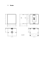
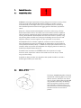
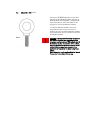
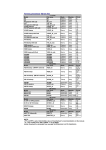
VS18 DR
USER MANUAL
CONTENTS
1. Introduction
2. Unpacking
3. Connectors/Cabling
4. Amplification & Power Handling
5. Crossovers
6. Equalisation/Positioning
7. Dimensions
8. Technical Specifications
9. Rigging & Suspension
9.1
9.2
9.3
General Safety Advice
SECUR ET – VTH Pole Mount
SECUR ET – VEB Eyebolt
10. System Configurations & OEM Controllers
11. VS18DR Service Parts & Accessories
12. Warranty
13. Declaration of Conformity
1.
Introduction
The Tannoy VS18DR is a direct radiating subwoofer designed to compliment Tannoy V
series loudspeakers where high definition sound reinforcement at low/ultra low
frequencies with increased headroom is required.
The VS18DR extends the frequency response of systems to below 30Hz, making it ideal
for club, theatre and concert sound applications. This powerful loudspeaker is capable
of delivering high sound pressure levels with extremely low distortion and power
compression while maintaining a uniform frequency response throughout its dynamic
range.
The VS18DR comprises one high efficiency 458mm (18”) drive unit. The cabinet is
constructed from multiple-ply hardwood, which will survive the punishment that
speaker systems are subjected to on the road and in club installations.
The VS18DR features recessed carrying handles rigging points, and blank plate for a
top-mounted stand socket, which serves as a base for locating the main full range or
mid/high speakers in the air. By using 35mm tubing the need for a tripod stand can be
eliminated.
2.
Unpacking
Every Tannoy VS18DR is carefully inspected before packing. After unpacking your
loudspeaker, please inspect for any exterior physical damage, and save the carton and
any relevant packaging materials in case the loudspeaker again requires packing and
shipping. In the event that damage has been sustained in transit notify your dealer
immediately.
3.
Connectors/Cabling
The VS18DR is fitted with 4-pole Neutrik Speakon connectors. Speakon has the
following advantages over EP and XLR type connectors: All terminations are solderless;
this makes life easier at the time of installation or when field servicing is required.
Contacts will accept 6 sq. mm wires with an outside diameter of up to 15mm and a
current rating of 30 Amps. The pins of the 2 Speakon sockets on the input panel are
paralleled within the enclosure. Tannoy has adopted the conventional wiring standard
for the VS15HL product: Pin 1+ is Positive
Pin 1- is Negative
For a worldwide list of Neutrik distributors see http://www.neutrik.com/
Cable choice consists mainly of selecting the correct cross sectional area in relation to
the cable length and the load impedance. A small cross sectional area would increase
the cables series resistance, inducing power loss and response variations (damping
factor).
Connectors should be wired with a minimum of 2.5 sq. mm (12 gauge) cable. This will
be perfectly satisfactory under normal conditions. In the case of very long cable runs
the wire size should exceed this, refer to the following table for guidance:-
CABLE RUN (m)
C.S.A. OF EACH
CONDUCTOR (mm)
CABLE
RESISTANCE Ω
% POWER LOSS
INTO 8Ω LOAD
% POWER LOSS
INTO 4Ω LOAD
10
2.5
4.0
6.0
2.5
4.0
6.0
2.5
4.0
6.0
2.5
4.0
6.0
0.14
0.09
0.06
0.35
0.22
0.14
0.69
0.43
0.29
1.38
0.86
0.58
1.7
1.1
0.73
4.3
2.7
1.8
8.6
5.4
3.6
17.0
11.0
7.2
3.5
2.2
1.5
8.6
5.4
3.6
17.0
11.0
7.2
35.0
22.0
14.0
25
50
100
4.
Amplification & Power Handling
As with all professional loudspeaker systems, the power handling is a function of voice
coil thermal capacity. Care should be taken to avoid running the amplifier into clip
(clipping is the end result of overdriving any amplifier). Damage to the loudspeaker will
be sustained if the amplifier is driven into clip for any extended period of time.
Headroom of at least 3dB should be allowed. When evaluating an amplifier, it is
important to take into account its behaviour under low impedance load conditions. A
loudspeaker system is highly reactive and with transient signals it can require more
current than the nominal impedance would indicate.
Generally a higher power amplifier running free from distortion will do less damage to
the loudspeaker than a lower power amplifier continually clipping. It is also worth
remembering that a high powered amplifier running at less than 90% of output power
generally sounds a lot better than a lower power amplifier running at 100%. An
amplifier with insufficient drive capability will not allow the full performance of the
loudspeaker to be realised.
It is important when using different manufacturers’ amplifiers in a single installation
that they have very closely matched gains, the variation should be less than +/- 0.5dB.
This precaution is important to the overall system balance when only a single active
crossover is being used with multiple cabinets; it is therefore recommended that the
same amplifiers be used throughout.
5.
Crossovers
The VS18DR has been designed to be used in conjunction with Tannoy controllers for
optimum performance, these provides specific crossover and equalisation functions for
the V series combinations as well as combinations of other Tannoy products. Of course
the VS18DR is compatible with other OEM controllers/crossovers. For Optimum
performance please refer to the section on System Configurations & OEM Controllers.
6.
Equalisation/Positioning
The VS18DR is designed to need no equalisation or correction to overcome system
limitations. As a result, it will only need equalisation to compensate for difficult acoustic
environments.
Excess equalisation can reduce system headroom, and introduce phase distortion
resulting in greater problems than it cures. If equalisation is required then it should be
applied gently and smoothly. Violent equalisation will be detrimental to the overall
sound quality.
The frequency band over which a subwoofer operates is essentially omni-directional,
therefore efficiency of the VS18DR may be further enhanced if the unit is placed
against a wall, where the radiation in the forward plane will be doubled due to the
addition of the reflected rear directed energy, and a 3dB increase in sound pressure
will occur. If another boundary is introduced, say a floor, then the effective radiation
space is halved again, resulting in a further 3dB lift, and if placed in a corner, once
again the sound pressure level will increase by a further 3dB.
7.
Dimensions
43.0
710
624.0
653
555.0
277.5
290.0
566.4
VS18 DR
VIEW OF TOP
VIEW OF BASE
8.
Technical Specifications
Frequency Response (1) +/- 3dB
27Hz - 240Hz
Recommended Amplifier Power
600 - 1200 Watt / 8Ω
Power Handling
Average(2) Programme Peak (10ms)
600 watt
1200 watt 2400 watt
Sensitivity (1)
2.83 volt @ 1m
99 dB
102 dB (half space conditions)
Maximum SPL (3)
@ 1m
Average Peak
130 dB 136 dB
Impedance
Nominal
Minimum
Distortion
0.1 Full Power
100 Hz
250 Hz
0.01 Full Power
100 Hz
250 Hz
8Ω
7Ω
2nd Harmonic
3rd Harmonic
0.2 5%
0.1 9%
0.2 %
0.1 5%
2nd Harmonic
3rd Harmonic
0.1 9%
0.1 %
0.1 4%
0.1 1%
Driver Complement
1 x 18” (458mm) LF Driver
Type number 4505
Recommended Crossover Point
70Hz - 240Hz, 24dB/octave
Recommended High-pass filter -25Hz, 24dB/octave
Enclosure
18mm (5/8”) birch plywood
Protective Grille
Foam covered, powder coated perforated steel
Finish
Textured black paint (optional in white)
Connectors
2 x Speakon NL4MPR IN/OUT
Fittings
4 x Recessed carrying handles
1 x Blanking plate allows installation of a 35mm pole-mounting
socket
8 x M10 flying inserts.
4 x Rubber feet
Dimensions
710mm(H) x 653mm(W) x 555mm(D)
27 15/16 “(H) x 25 9/16”(W) x 21 7/8”(D)
Weight
50kg (110lbs 4oz)
NOTES:
(1) Average over stated bandwidth. Measured at 1m on axis, in an anechoic chamber.
(2) Long term power handling capacity as defined in EIA standard RS - 426A.
(3) Unweighted pink noise input, measured at 1m in half space conditions.
Tannoy operates a policy of continuous research and development. The introduction of new materials or manufacturing
methods will always equal or exceed the published specifications which Tannoy reserve the right to alter without prior
notice. Please verify the latest specifications when dealing with critical applications.
9.
Rigging & Suspension
9.1
General Safety Advice
!
WARNING: As the legal requirements for flying change from country to country, please
consult you local safety standards office before installing any product. We also
recommend that you thoroughly check any laws and bylaws prior to commencing
work. Qualified personnel trained in safe rigging practices should only suspend the
system.
Whenever a Tannoy Professional loudspeaker is fixed to a surface using a Tannoy
Professional hardware device, the installer must ensure that the surface is capable of
safely and securely supporting the load. The hardware employed must be safely and
securely, attached both to the loudspeaker and also to the surface in question, using
only the fixing holes provided. Secure fixings to the building structure are vital. Seek
help from architects, structural engineers or other specialists if in any doubt.
All loudspeakers flown in theatres, nightclubs, conference centre or other places of
work and entertainment must, be provided with an independent, correctly rated and
securely attached secondary safety – in addition to the principle hardware device. This
secondary safety must prevent the loudspeaker from dropping more than 150mm (6”)
should the principle hardware device fail.
Threaded inserts are fitted to the VS18DR to allow the suspension of a single
enclosure. Never suspend one enclosure from another to form an array or cluster
using only these fittings.
If eyebolts are being used then only forged shoulder eyebolts should be used with a
thread length of 30mm (see section 8.3).
9.2
SECUR – ET VTH Pole Mount
The Tannoy VS18DR loudspeaker is fitted as
standard with a blanking plate on top of the
cabinet. However, should you ever wish to
mount a V series cabinet above the VS18DR
using standard 35mm tube, this blanking
plate can be quickly and easily removed
and replaced by a VTH pole mount. The
same screws that secure the blanking plate
should be used to secure the VTH in
position.
9.3
SECUR ET – VEB Eyebolt
7.
The Tannoy VS18DR loudspeaker can be flown
with high quality VEB M10 eyebolts with collar to
BS4278:1984. The loudspeaker is equipped with
internal steel braces, which also double as the
flying points, and accept VEB M10 eyebolts.
To install the VEB M10 eyebolts remove the
original M10 counter sunk screws from the
locations you wish to install the VEB M10 eyebolts.
Then replace these counter sunk M10 screws with
the VEB M10 eyebolts.
FIG 1.
!
Important: It is imperative for safety reasons that
two eyebolts linked to two independently fixed
straps are used per cabinet. VEB eyebolts should
be installed into the relative sides of the cabinet,
and should NEVER be installed on the top of the
cabinet. Never suspend one enclosure from
another to form an array or cluster using these
fittings.
Never attempt to use formed eyebolts i.e. formed
from a steel rod and bent into an eye.
10.
System Configurations & OEM Controllers
With the vast array of digital loudspeaker management systems available it is
inevitable that the user may opt to use a controller other than a Tannoy controller as
part of a large scale integrated system. The VS18DR has been designed to need no
external equalisation to overcome system limitations. Below is a list of recommended
parameters; these parameters can be further tailored depending on the acoustic
environment or specific application:Parameter
Unit/Name
(dB)
User definable
(ms)
User definable
Positive
Freq (Hz)
25
Slope (dB/oct)
Filter Shape
24
Butterworth
LPF
Freq (Hz)
Slope (dB/oct)
Filter Shape
70 – 240
24
Butterworth
PEQ 1
Freq (Hz)
Level (dB)
Type
Q / Bandwidth
35
+4
Parametric
2.0 / 0.5
Gain
Delay
Polarity
HPF
11.
12.
VS15HL Service Parts & Accessories
Part Number
7900 0599
7900 0603
Description
Driver Kit - 4505
Recone Kit - 4505
8001 2860
8001 2870
VTH – Secur ET – Top Hat (Black)
VTH – Secur ET – Top Hat (White)
8001 2820
VEB – Secur ET – Eyebolts M10
Warranty
No maintenance of the VS18DR loudspeaker is necessary.
All Tannoy professional loudspeaker products are covered by a 5 year warranty from
the date of manufacture subject to the absence of misuse, overload or accidental
damage. Claims will not be considered if the serial number has been altered or
removed. A Tannoy Professional dealer or service agent should only carry out work
under warranty. This warranty in no way affects your statutory rights. For further
information please contact your dealer or distributor in your country. If you cannot
locate your distributor please contact Customer Services, Tannoy Ltd at the address
given below.
Customer Services
Tannoy Ltd.
Rosehall Industrial Estate
Coatbridge
Strathclyde
ML5 4TF
Scotland
Telep hone:
Fax :
E-Mail:
01236 420199
+44 1236 420199
0 1236 428230
+44 1236 428230
[email protected]
(National)
(International)
(National)
(International)
DO NOT SHIP ANY PRODUCT TO TANNOY WITHOUT PREVIOUS AUTHORISATION
Our policy commits us to incorporating improvements to our products through
continuous research and development. Please confirm current specifications for critical
applications with your supplier.
13.
Declaration of Conformity
The following apparatus is/are manufactured in the United Kingdom by Tannoy Ltd of Rosehall
Industrial estate, Coatbridge, Scotland, ML5 4TF and conform(s) to the protection requirements
of the European Electromagnetic Compatibility Standards and Directives relevant to Domestic
Electrical Equipment. The apparatus is designed and constructed such that electromagnetic
disturbances generated do not exceed levels allowing radio and telecommunications
equipment and other apparatus to operate as intended, and, the apparatus has an adequate
level of intrinsic immunity to electromagnetic disturbance to enable operation as specified and
intended.
Details of the Apparatus:
Tannoy Contractor Loudspeaker
Model Number: VS18DR
Associated Technical File:
EMCVS18DR
Applicable Standards:
EN 50081-1 Emission
EN 50082-1 Immunity
Signed:
Position:
Engineering Director
Tannoy Professional
Date:
4th May 2003
E: [email protected]
E: [email protected]
Tannoy adopts a policy of continuous improvement and product specification is subject to change.
GH April 27, 2003
T: +44 (0) 1236 420199 F: +44 (0) 1236 428230
T: (519) 745 1158
F: (519) 745 2364
6481 0395
Tannoy United Kingdom
Tannoy North America
Issue 1.0
For Tannoy Ltd