1
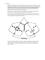
User Manual CONTENTS 1. Introduction 2. Unpacking 3. Connectors/Cabling 4. Polarity Checking 5. Amplification & Power Handling 6. Crossovers 7. Equalisation 8. Arraying 9. Dimensions 10. Performance Data 11. Technical Specifications 12. Rigging & Suspension 12.1 12.2 12.3 12.4 12.5 12.6 12.7 General Safety Advice Secur – ET VMY Yoke bracket Secur – ET VMB Wall mounting Bracket Secur – ET VEB Eyebolts Secur – ET VTH Pole mount Secur – ET VCS Ceiling Saddle Secur – ET VPC Pole Clamp 13. System Configuration & OEM Controllers 14. V12 Recommended Service Parts & Accessories 15. Warranty 16. Declaration of Conformity 1. Introduction The Tannoy V12 professional loudspeaker has been designed for a wide variety of sound reinforcement applications requiring extended frequency response from a powerful yet compact system, capable of delivering high sound pressure levels with extremely low distortion, resulting in outstanding clarity, definition and detail. The V12 comprises one 12 inch Dual Concentric driver in which the low frequency (LF) and high frequency (HF) sources are coincidentally aligned to a point source, resulting in a smooth uniform frequency response over a wide area of coverage either as a portable stand alone system or in a multi-cabinet array. The sophisticated CAD designed waveguide combines 90 degree conical dispersion and excellent acoustic impedance characteristics. As the system is a point source, clusters and arrays have minimal lobing. These features are inherent and achieved without the use of any electronic signal processing. The asymmetric cabinet profile allows flexible and discreet installation. As a foreground system, installation is made simple with a range of Secur-ET mounting hardware, designed specifically for the V series – or the system can be flown using the integral M10 inserts. For portable stage use the birch ply cabinet has a recessed carrying handle on the rear of the cabinet and a blanking plate, which can be removed to install an optional pole mount. As a versatile low profile stage monitor, the conical coverage pattern gives the performer greater freedom of movement than allowed by conventional horn loaded designs. The V12 has been designed for use with the Tannoy TX2 controller, which will equalise the system resulting in improved bass performance as well as providing a 2-way crossover function, operating at 100Hz, for use with separate sub-bass systems. 2. Unpacking Every Tannoy V12 product is carefully tested and inspected before being packaged and leaving the factory. After unpacking your loudspeaker, please inspect for any exterior physical damage, and save the carton and any relevant packaging materials in case the loudspeaker again requires packing and shipping. In the event that damage has been sustained in transit notify your dealer immediately. 3. Connectors/Cabling The V12 is fitted with 4-pole Neutrik Speakon connectors. Speakon has the following advantages over EP and XLR type connectors: All terminations are solderless; this makes life easier at the time of installation or when field servicing is required. Contacts will accept 6 sq. mm wire with an outside diameter of up to 15mm and a current rating of 30 Amps. The pins of the 2 Speakon sockets identified input/output on the rear of the input panel are paralleled within the enclosure. Tannoy have adopted the conventional wiring standard for the V12 product :Pin 1+ is Positive Pin 1- is Negative For a worldwide list of Neutrik distributors see http://www.neutrik.com/ Cable choice consists mainly of selecting the correct cross sectional area in relation to the cable length and the load impedance. A small cross sectional area would increase the cables series resistance, inducing power loss and response variations (damping factor). Connectors should be wired with a minimum of 2.5 sq. mm (12 gauge) cable. This will be perfectly satisfactory under normal conditions. In the case of very long cable runs the wire size should exceed this, refer to the following table for guidance:- CABLE RUN (m) C.S.A. OF EACH CONDUCTOR (mm) CABLE RESISTANCE Ω Ω % POWER LOSS INTO 8Ω Ω LOAD % POWER LOSS INTO 4Ω Ω LOAD 10 2.5 4.0 6.0 2.5 4.0 6.0 2.5 4.0 6.0 2.5 4.0 6.0 0.14 0.09 0.06 0.35 0.22 0.14 0.69 0.43 0.29 1.38 0.86 0.58 1.7 1.1 0.73 4.3 2.7 1.8 8.6 5.4 3.6 17.0 11.0 7.2 3.5 2.2 1.5 8.6 5.4 3.6 17.0 11.0 7.2 35.0 22.0 14.0 25 50 100 4. Polarity Checking It is most important to check the polarity of the wiring before the speaker system is flown. A simple method of doing this without a pulse based polarity checker for LF units is as follows: Connect two wires to the +ve and -ve terminals of a PP3 battery. Apply the wire which is connected to the +ve terminal of the battery to the speaker cable leg which you believe to be connected to pin 1+ of the speaker connector and likewise the -ve leg of the battery to pin 1-. If you have wired it correctly the LF drive unit will move forward, indicating the wiring is correct. All that remains now is to connect the +ve speaker lead to the +ve terminal on the amplifier and the -ve lead to the -ve terminal on the amplifier. If however the LF driver moves backwards, the input connections need to be inverted. If problems are encountered, inspect the cable wiring in the first instance. It should also be noted that different amplifier manufacturers utilise different pin configurations and polarity conventions, if you are using amplifiers from more than one manufacturer, check the polarity at the amplifiers as well as the loudspeakers. 5. Amplification & Power Handling As with all professional loudspeaker systems, the power handling is a function of voice coil thermal capacity. Care should be taken to avoid running the amplifier into clip (clipping is the end result of overdriving any amplifier). Damage to the loudspeaker will be sustained if the amplifier is driven into clip for any extended period of time. Headroom of at least 3dB should be allowed. When evaluating an amplifier, it is important to take into account its behaviour under low impedance load conditions. A loudspeaker system is highly reactive and with transient signals it can require more current than the nominal impedance would indicate. Generally a higher power amplifier running free of distortion will do less damage to the loudspeaker than a lower power amplifier continually clipping. It is also worth remembering that a high powered amplifier running at less than 90% of output power generally sounds a lot better than a lower power amplifier running at 100%. An amplifier with insufficient drive capability will not allow the full performance or the loudspeaker to be realised. (See technical specifications section for recommended amplifier power) It is important when using different manufacturers amplifiers in a single installation that the have very closely matched gains, the variation should be less than +/- 0.5dB. This precaution is important to the overall system balance when only a single active crossover is being used with multiple cabinets; it is therefore recommended that the same amplifiers be used throughout. 6. Crossovers The V12 is supplied as standard for passive operation via the internal crossover network. If higher peak outputs and additional low frequency output is required then the V12 can be used in conjunction with the Tannoy TX2 controller/crossover which provides high pass filtering and a degree of parametric equalisation, as well as a fixed crossover point for use with sub-bass loudspeakers (See the TX2 user manual for further information). The Tannoy TDX2 Digital controller will also perform the above functions with additional control and features including limiting and delay (See the relevant literature on the TDX2 for further information). 7. Equalisation The V12 loudspeakers are designed to need no equalisation or correction to overcome system limitations. As a result, it will only need equalisation to compensate for difficult acoustic environments. Over equalisation can reduce system headroom, and introduce phase distortion resulting in greater problems than cures. If equalisation is required then it should be applied gently and smoothly. The V12 loudspeaker is a point source, phase coherent designs and violent equalisation will be detrimental to the overall sound quality. When a loudspeaker is used in close proximity to another, comb filtering effects can create coverage problems, comb filtering creates an uneven frequency response across the coverage area due to constructive and destructive interference effects between the sources. The amount of comb filtering is affected by the spacing of the relative sound sources. Minimising this effect cannot be cured by equalisation (see the following section for more details). 8. Arraying As discussed in the previous section, comb filtering is a phenomenon, which cannot not be cured by equalisation. Small alterations to loudspeaker positions can have the effect of minimising problematic combing frequencies. Arrays should be constructed so that the individual coverage patters of each loudspeaker combine with minimal overlap. The design of the V12 cabinet greatly simplifies the creation of effective arrays, allowing seamless wide (140 degree) horizontal coverage using two loudspeakers without the need for tedious experimentation. By placing the V12 cabinets with the 30 degree angled rear panels together, minimal dispersion pattern overlap is achieved, guaranteeing an extraordinarily smooth transition. In many applications the 90-degree dispersion pattern may be sufficient in the horizontal plane. It is also possible to stack the cabinets vertically using the above method, say for use in a central cluster, where greater vertical dispersion is required. 9. 2 1 V 60deg As shown in the above diagram, one of the V12 cabinets is inverted to allow the optimum splay angle to be achieved. The grill can be simply removed from this cabinet and be replaced in the correct orientation. The grill is held in position by the two fixing screws on the top and bottom lips of the cabinet. 12. Rigging & Suspension 12.1 General Safety Advice ! The Tannoy Professional hardware covered in this guide has been designed to offer quick, simple, cost effective and secure solutions for mounting specific Tannoy Professional loudspeakers. This hardware has been designed and manufactured with a high safety load factor for its specific role. To ensure the safest possible use of the hardware covered in this guide, it must be assembled in strict accordance with the instructions specified. The information in these manuals relating to the assembly and the safe use of these accessories must be understood and followed. The installation of Tannoy Professional loudspeakers using the dedicated hardware should only ever be carried out by fully qualified installers, in accordance with all the required safety codes and standards that are applied at the place of installation. WARNING: As the legal requirements for flying change from country to country, please consult you local safety standards office before installing any product. We also recommend that you thoroughly check any laws and bylaws prior to commencing work. Tannoy Professional hardware has been designed for use with specific Tannoy Professional loudspeakers, and is not designed or intended for use with any other Tannoy Professional products, or any other devices. Using Tannoy Professional hardware for any purpose other than that indicated in this guide is considered to be improper use. Such use can be very dangerous as overloading, modifying, assembling in anyway other than that clearly stated in the manual, or damaging Tannoy Professional hardware will compromise safety. The component parts of any Tannoy Professional hardware device must only be assembled using the accessory kits supplied and in strict compliance with the user manual. The use of other accessories or non-approved methods of assembly may result in an unsafe hardware system by reducing the load safety factor. Welding, or any other method of permanently fixing hardware components together or to the integral fixing points in the cabinet should never be used. Whenever a Tannoy Professional loudspeaker is fixed to a surface using a Tannoy Professional hardware device, the installer must ensure that the surface is capable of safely and securely supporting the load. The hardware employed must be safely, securely, and in accordance with the manual, attached both to the loudspeaker and also to the surface in question, using only the fixing holes provided as standard and covered in the manual. Secure fixings to the building structure are vital. Seek help from architects, structural engineers or other specialists if in any doubt. All loudspeakers flown in theatres, nightclubs, conference centre or other places of work and entertainment must, be provided with an independent, correctly rated and securely attached secondary safety – in addition to the principle hardware device. This secondary safety must prevent the loudspeaker from dropping more than 150mm (6”) should the principle hardware device fail. 12.2 SECUR ET – VMY Yoke Bracket The VMY is an adjustable yoke bracket (available in both black and white), allowing the user to fly the Tannoy V12 loudspeaker in either portrait or landscape orientations using the same bracket (Figures 1 & 2). ! The Tannoy V12 loudspeaker is attached to the bracket using the M10 bolts and washers supplied in the accessory pack. Only the screws, fasteners, shakeproof and plain washers specified on figure 3. should be used to assemble the VMY bracket Pivot studs (Figure 3.) (Supplied with the VMY) are attached to the cabinet using the M10 bolts supplied. These bolts locate on the M10 inserts in the cabinet. The VMY adjustable yoke bracket then connects to the centre of these mounting plates (using the M10 screws supplied). These bracket pick up points which are in line with the bracket’s axis of rotation, are also positioned on the centre of gravity of the V12 in both orientations to allow easy adjustment for optimum coverage. The vertical distance between the apex of the VMY and the top of the Tannoy V12 loudspeaker can be adjusted by connecting to varying mounting points on the bracket allowing varying degrees of vertical rotation. The top centre fixing hole of the VMY then provides a pick up point for a variety of Tannoy Professional hardware accessories including the VMB wall mounting plate (shown in Figure 2.), the VCS ceiling saddle, and the VPC pole clamp. Fig.1 Fig. 2 Use the table of parts along with the assembly drawing (Figure 3.) to assemble the VMY. Figure 4 shows the VMY assembled. Fig 3. Number on Assembly View (Fig 3.) 1 2 3 4 5 6 7 8 9 10 11 12 Description Hanging Bracket Cross Member Pivot Stud M10 Plain Washer M8 Spring Washer M10 Spring Washer M10 x 30mm Screw M8 x 20mm Screw M10 x 30mm Screw M10 Nyloc Nut Friction Washer 30mm Square Blank Plug Fig 4. Quantity 2 1 2 2 2 4 2 2 2 2 2 2 12.3 SECUR ET – VMB Wall Mounting Bracket The VMB is wall mounting bracket for the attachment of a VMY, available in both black and white finishes, allowing the user secure the Tannoy V12 loudspeaker in either portrait or landscape orientations to a wall. FIG 1. The Tannoy V12 loudspeaker is attached to the bracket using the accessories supplied. This wall-mounting bracket has a larger wall plate than previous models to maximise the integrity of fixing obtained. There are also two holes either side of the fixing beam to allow the speaker cable the pass through the wall plate and along the fixing beam to the terminal panel resulting in a more discrete installation. The fixing beam on the VMB has a number of mounting points from which the VMY can be attached at varying distances from the mounting surface. Only the screws, fasteners, shakeproof and plain washers specified on figure 3. should be used to assemble the VMB bracket ! 1 FIG 2. 2 3 FIG 3. 4 5 Number on Fig 3. 1 2 3 4 5 6 Description VMB Wall Bracket M10 Nyloc Nut M10 Plain Washer 30mm Square Blank Plug Nylon Spacer M10 x 85mm Screw Quantity 1 1 1 1 1 1 6 12.4 SECUR ET – VEB Eyebolt The Tannoy V12 loudspeaker can be flown with high quality VEB M10 eyebolts with collar to BS4278:1984. The loudspeakers are equipped with internal steel braces, which also double as the flying points, and accept VEB M10 eyebolts. To install the VEB M10 eyebolts remove the original M10 counter sunk screws from the locations you wish to install the VEB M10 eyebolts. Then replace these counter sunk M10 screws with the VEB M10 eyebolts. The M10 insert on the rear of the cabinet also accepts a VEB M10 eyebolt and should only be used for tilting the loudspeaker to the desired angle. FIG 1. ! Important: It is imperative for safety reasons that two eyebolts linked to two independently fixed straps are used per cabinet. VEB eyebolts should be installed into the relative sides of the cabinet, and should NEVER be installed on the top of the cabinet. Never suspend one enclosure from another to form a line array or cluster using these fittings. The correct method is shown in figure 2. Never attempt to use formed eyebolts i.e. formed from a steel rod and bent into an eye. Only use the outer fixing points on the top and sides of the V12 cabinet for fixing eyebolts. The inner two fixing points on each side of the cabinet are for dedicated bracketry (VMY) only. p r o f e s s i o n a l p r o f e s s i o n a l p r o f e s s i o n a l FIG 2. p r o f e s s i o n a l 12.5 SECUR – ET VTH Pole Mount The Tannoy V12 loudspeaker is fitted as standard with a blanking plate on the base of the cabinet. However, should you ever wish to mount the V12 onto a standard 35mm pole mount this blanking plate can be quickly and easily removed and replaced by a VTH pole mount. The same screws which secure the blanking plate should be used to secure the VTH in position. 12.6 SECUR – ET VCS Ceiling Saddle VCS The VCS ceiling saddle available in both black and white finishes, and is to be used in conjunction with the VMY and a length of M10 threaded rod (not supplied by Tannoy Limited). The VCS ceiling saddle allows the Tannoy V12 loudspeaker to be suspended at a user defined distance from the ceiling as shown in Figure 1. Included with the VCS is an M10 nut. This should be used to secure and lock the threaded rod in place at the top of the ceiling saddle. Fig 1. 12.7 SECUR – ET VPC Pole Clamp The VPC pole clamp can be used along with the VMY yoke bracket to suspend a Tannoy V12 loudspeaker from an overhead bar, truss or suitable structure. Only the parts supplied should be used to secure the VPC to the VMY yoke bracket. The following items are included with each VPC:- Description Quantity VPC Pole Clamp M10 Washer M10 x 50mm Screw M10 Nyloc Nut (Black) 1 1 1 1 13. System Configurations & OEM Controllers With the vast array of digital loudspeaker management systems available it is inevitable that the user may opt to use a controller other than the TX2 & TDX2 as part of a large scale integrated system. The V12 has been designed to need no external equalisation to overcome system limitations. If the V12 is to be used alone with additional bass enhancement required and have the frequency response limits tighter than +/- 3dB as stated in section 11, then apply the parameters in the table below for optimised performance:- Parameter Unit/Name Gain Delay Polarity (dB) (ms) User definable User definable Positive HPF â Freq (Hz) Slope (dB/oct) Filter Shape 42.5 24 Butterworth LPF Freq (Hz) Slope (dB/oct) Filter Shape Thru NA NA PEQ 1 â Freq (Hz) Level (dB) Type Q / Bandwidth 62.5 +7 Parametric 2.5 / 0.3969 PEQ 2 Freq (Hz) Level (dB) Type Q / Bandwidth 130 -2 Parametric 2 / 0.5 PEQ 3 Freq (Hz) Level (dB) Type Q / Bandwidth 655 -2.3 Parametric 6.7 / 0.1487 PEQ 4 Freq (Hz) Level (dB) Type Q / Bandwidth 981 +3.3 Parametric 7.1 / 0.1403 PEQ 5 Freq (Hz) Level (dB) Type Q / Bandwidth 12500 +3 Hi Shelf NA â Note : When using the V12 with subs, set HPF @ 80 – 110Hz (24dB/oct LR) and omit PEQ1. 14. V12 Service Parts & Accessories Part Number 7900 0433 7900 0441 7900 0199 7300 0824 Description Driver Kit - 3142 Recone Kit - 3142 HF Diaphragm Kit Crossover 8001 2780 8001 2790 8001 2800 8001 2810 8001 2820 8001 2830 8001 2840 8001 2850 8001 2860 8001 2870 VMY – Secur ET – Yoke Adjustable (Black) VMY – Secur ET – Yoke Adjustable (White) VMB – Secur ET – Wall Bracket (Black) VMB – Secur ET – Wall Bracket (White) VEB – Secur ET – Eyebolts M10 VCS – Secur ET – Ceiling Saddle (Black) VCS – Secur ET – Ceiling Saddle (White) VPC – Secur ET – Pole Clamp VTH – Secur ET – Top Hat (Black) VTH – Secur ET – Top Hat (White) 8000 0649 8000 0650 8000 0651 8000 0652 8000 0653 Tannoy TX2 Active System Controller UK220/240v Tannoy TX2 Active System Controller EUR220/240v Tannoy TX2 Active System Controller AUS20/240v Tannoy TX2 Active System Controller USA100/120v Tannoy TX2 Active System Controller JAP100/120v 8001 1930 8001 1940 8001 1950 Tannoy TDX2 Digital System Controller 90 – 250V UK Tannoy TDX2 Digital System Controller 90 – 250V EUR Tannoy TDX2 Digital System Controller 90 – 250V USA 15. Warranty No maintenance of the V12 loudspeakers is necessary. All Tannoy professional loudspeaker products are covered by a 5 year warranty from the date of manufacture subject to the absence of misuse, overload or accidental damage. Claims will not be considered is the serial number has been altered or removed. Work under warranty should only be carried out by a Tannoy Professional dealer or service agent. This warranty in no way affects your statutory rights. For further information please contact your dealer or distributor in your country. If you cannot locate your distributor please contact Customer Services, Tannoy Ltd at the address given below. Customer Services Tannoy Ltd. Rosehall Industrial Estate Coatbridge Strathclyde ML5 4TF Scotland Telephone: 01236 420199 +44 1236 420199 Fax: 01236 428230 +44 1236 428230 E-Mail: [email protected] (National) (International) (National) (International) DO NOT SHIP ANY PRODUCT TO TANNOY WITHOUT PREVIOUS AUTHORISATION Our policy commits us to incorporating improvements to our products through continuous research and development. Please confirm current specifications for critical applications with your supplier. 16. Declaration of Conformity The following apparatus is/are manufactured in the United Kingdom by Tannoy Ltd of Rosehall Industrial estate, Coatbridge, Scotland, ML5 4TF and conform(s) to the protection requirements of the European Electromagnetic Compatibility Standards and Directives relevant to Domestic Electrical Equipment. The apparatus is designed and constructed such that electromagnetic disturbances generated do not exceed levels allowing radio and telecommunications equipment and other apparatus to operate as intended, and, the apparatus has an adequate level of intrinsic immunity to electromagnetic disturbance to enable operation as specified and intended. Details of the Apparatus: Associated Technical File: Applicable Standards: Electrical Safety: Tannoy Contractor Loudspeaker Model Number: V12 EMCV12 EN 50081-1 Emission EN 50082-1 Immunity EN 60065 Signed: Position: Engineering Director – Professional Products Tannoy Professional Date: 10/06/2002 For Tannoy Ltd Tannoy Loudspeakers are manufactured in Great Britain by : Tannoy Ltd, Rosehall Industrial Estate, Coatbridge, Strathclyde, ML5 4TF, SCOTLAND Telephone: +44 (0)1236 420199 Fax: +44 (0)1236 428230 Tannoy North America Inc, Suite 1. 335 Gage Avenue, Kitchener, Ontario, CANADA, N2M 5E1 Telephone: (519) 745 1158 Fax: (519) 745 2364 Tannoy Nederland BV, Anthonetta Kuijlstraat 19, 3066 GS, Rotterdam THE NETHERLANDS Telephone: (010) 2860554 Fax: (010) 2860431 Issue 1.0 Part No. 6481 0377 GH 10 th June 2002