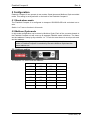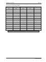
1
Flashlink Compact II FC-3G-EO-OE-36+2C FC-3G-EO-36+1C FC-3G-EO-OE-36+1C FC-3G-OE-36+2C FC-3G-EO-36+2C FC-3G-OE-36 FC-3G-EO-36 FC-3G-EO-OE-36 FC-3G-OE-18 FC-3G-EO-18 FC-3G-OE-36+1C User manual Rev. A Nevion Nordre Kullerød 1 3241 Sandefjord Norway Tel: +47 33 48 99 99 nevion.com Flashlink Compact II Rev. A Nevion Support Nevion Europe Nevion USA P.O. Box 1020 3204 Sandefjord, Norway Support phone 1: +47 33 48 99 97 Support phone 2: +47 90 60 99 99 1600 Emerson Avenue Oxnard, CA 93033, USA Toll free North America: (866) 515-0811 Outside North America: +1 (805) 247-8560 E-mail: [email protected] See http://www.nevion.com/support/ for service hours for customer support globally. Revision history Current revision of this document is the uppermost in the table below. Rev. Repl. Date Sign A - 2013-07-03 MS Change description First official release nevion.com | 2 Flashlink Compact II Rev. A Contents Revision history ........................................................................................................ 2 1 Product overview ................................................................................................... 4 1.1 Product versions ........................................................................................................... 4 2 Specifications ........................................................................................................ 5 2.1 Front view ..................................................................................................................... 7 2.1.1 FC-3G-EO-18 ............................................................................................................. 7 2.1.2 FC-3G-EO-36 ............................................................................................................. 8 2.1.3 FC-3G-OE-18 ............................................................................................................. 9 2.1.4 FC-3G-OE-36 ............................................................................................................10 2.1.5 FC-3G-EO-OE-36 .....................................................................................................11 2.1.6 CWDM filter placement .............................................................................................12 2.2 Rear view .....................................................................................................................13 2.2.1 FC-3G-EO-18 ............................................................................................................13 2.2.2 FC-3G-EO-36 ............................................................................................................13 2.2.3 FC-3G-OE-18 ............................................................................................................14 2.2.4 FC-3G-OE-36 ............................................................................................................14 2.2.5 FC-3G-EO-OE-36 .....................................................................................................15 3 Connections ........................................................................................................ 16 1.1.1 Pin-out POWER A and POWER B (DB9) ..................................................................16 1.2.1 Pin-out RS-422 (RJ45) ..............................................................................................16 4 Replacing fan modules ........................................................................................ 17 5 Configuration ....................................................................................................... 19 5.1 Stand-alone mode ........................................................................................................19 5.2 Multicon Gyda mode ....................................................................................................19 5.2.1 Address setting .........................................................................................................19 5.2.2 Multicon Gyda configuration ......................................................................................21 5.2.3 Multicon Gyda information .........................................................................................23 6 Upgrade firmware ................................................................................................ 24 7 Nevion SFP ......................................................................................................... 25 8 Laser safety precautions ..................................................................................... 26 General environmental requirements for Nevion equipment .................................. 27 Product Warranty.................................................................................................... 28 Appendix A Materials declaration and recycling information .................................. 29 A.1 Materials declaration ....................................................................................................29 A.2 Recycling information...................................................................................................29 nevion.com | 3 Flashlink Compact II Rev. A 1 Product overview The Flashlink compact II is a range of low power, low price and small form factor optical to electrical converters. It can convert up to 36 channels in 1RU and optically multiplex all channels onto two fibers with the use of two optional 18 channel CWDM filters. Both EO and OE converters have an SD/HD/3G-SDI reclocker and supports bypass for none broadcast bitrates. The Flashlink Compact II can be controlled and monitored by Multicon Gyda or configured to be a standalone converter. The optical conversions are based on Nevion’s hot pluggable SFP modules. The Flashlink Compact II is equipped with an extra power inlet for dual power supply redundancy, either from an extra SL-PWR-40/SL-PWR90, the 1RU FC-PWR or battery pack. 1.1 Product versions FC-3G-EO-18 FC-3G-OE-18 FC-3G-EO-36 FC-3G-OE-36 FC-3G-EO-OE-36 FC-3G-EO-36+1C FC-3G-OE-36+1C FC-3G-EO-OE-36+1C FC-3G-EO-36+2C FC-3G-OE-36+2C FC-3G-EO-OE-36+2C 18 channel electrical to optical converter 18 channel electrical to optical converter 36 channel electrical to optical converter 36 channel optical to electrical converter 18 channel optical to electrical converter and 18 channel electrical to optical converter 36 channel electrical to optical converter+ one CWDM filter 36 channel optical to electrical converter + one CWDM filter 18 channel optical to electrical converter and+ one CWDM filter 18 channel electrical to optical converter + one CWDM filter 36 channel electrical to optical converter + two CWDM filters 36 channel optical to electrical converter + two CWDM filters 18 channel optical to electrical converter and 18 channel electrical to optical converter + two CWDM filters All 18 channel versions are supplied with one SL-PWR-40 All 36 channel versions are supplied with one SL-PWR-90(can be used for all 18 channel versions without damage) Extra powers supplies can be ordered for all versions. nevion.com | 4 Flashlink Compact II Rev. A 2 Specifications General Power +12V to 16V DC / 48W, max(standard SFP) 36channel variants 24W, max(standard SFP) 18 channel variants Size 1.7” x 19” x 7.1” (H x W x D) 43.4mm x 482.6mm x 180.0mm (H x W x D) Control Options for Multicon Gyda control and status BITE (Built-In Test Equipment) Status LED in front Configurations DIP in back Operating temperature 0 to +45 °C Forced ventilation Four monitored fans, two on each side. Left to right airflow. Data rate reclocked: 270, 1485, 1485/1.001, 2970, 2970/1.001 Mbps Data rate non-reclocked: 1 to 2970 Mbps (Depending on SFP used) Supported standards SD, 270Mbps SMPTE259M HD, 1485Mbps SMPTE292-2008 3G, 2999Mbps SMPTE424M DVB-ASI EN50083-9. Fiber Transmission SMPTE297-2006 Electrical connector, BC IEC 61169-8 AES-3id (non-reclocked) AES-10/MADI (non-reclocked) Optical SDI input See Nevion SFP datasheets for specification. Optical SDI output See Nevion SFP datasheets for specification. nevion.com | 5 Flashlink Compact II Rev. A Electrical SDI input Connectors BNC, IEC 61169-8 Impedance 75ohm Cable equalization Automatic; 350m @270Mbps w/Belden 8281 250m @1485Mbps w/Belden 1694A 150m @ 2970Mbps w/Belden 1694A Input Return loss >15dB, 5-1485MHz >10dB, 1485-2970MHz Electrical SDI outputs Connectors BNC, IEC 61169-8 Impedance 75ohm Output signal level 800mV +/- 10% Output signal rise / fall time 20% - 80% - SD, 0.4ns – 1.5ns, <0.5ns rise/fall variation - HD/3G, < 270ps, <100ps rise/fall variation DC-offset 0V +/-0,5 Amplitude overshoot <10% Output return loss >15dB, 5-1485MHz >10dB, 1485-2970MHz 18 channel CWDM filter Number of channels Available wavelengths (nm) Connector Insertion loss (end to end, including connectors) Channel Spacing Passband Transmission circuit fibre Adjacent Channel Isolation Non-Adjacent Channel Isolation Directivity Connector Return loss Polarization depending loss Ripple in passband Operating Temperature Storage Temperature Optical Power 18 1271, 1291, 1311, 1331, 1351, 1371, 1391, 1411, 1431, 1451, 1471, 1491, 1511, 1531, 1551, 1571, 1591, 1611 LC/UPC 5dB typical 6dB max 20nm 13nm min 9/125um single mode 30dB min 40dB min 45dB min 45dB min 0.2dB max 0.5dB max 0 – 70 oC -40 – 85 oC 17mW max nevion.com | 6 Flashlink Compact II Rev. A 2.1 Front view 2.1.1 FC-3G-EO-18 Power A indicator: Power B indicator: Gives status on power supply connected to the Power A connector on the back side. Green: Power supply connected Orange: No or none working power supply connected Red: The lower converter is malfunctioning. Please contact Nevion support for advice. Gives status on power supply connected to the Power B connector on the back side. Green: Power supply connected Orange: No or none working power supply connected Red: The lower converter is malfunctioning. Please contact Nevion support for advice. 1 to 18 indicators: Gives status per SFP converter channel. Green: Valid input signal and reclocker in lock or bypass. Orange: Signal on input, but reclocker not in lock. Red: No valid input signal. No light: No valid Nevion SFP present. SFP: Cage for fitting dual transmitter non-MSA SFPs. nevion.com | 7 Flashlink Compact II Rev. A 2.1.2 FC-3G-EO-36 Power A indicator: Power B indicator: Gives status on power supply connected to the Power A connector on the back side. Green: Power supply connected Orange: No or none working power supply connected Red: The lower converter is malfunctioning. Please contact Nevion support for advice. Gives status on power supply connected to the Power B connector on the back side. Green: Power supply connected Orange: No or none working power supply connected Red: The lower converter is malfunctioning. Please contact Nevion support for advice. 1 to 18 indicators: Gives status per SFP converter channel. Green: Valid input signal and reclocker in lock or bypass. Orange: Signal on input, but reclocker not in lock. Red: No valid input signal. No light: No valid Nevion SFP present. Upper SFP: Cage for fitting dual transmitter non-MSA SFPs. Lower SFP: Cage for fitting dual transmitter non-MSA SFPs. nevion.com | 8 Flashlink Compact II Rev. A 2.1.3 FC-3G-OE-18 Power A indicator: Power B indicator: Gives status on power supply connected to the Power A connector on the back side. Green: Power supply connected Orange: No or none working power supply connected Red: The lower converter is malfunctioning. Please contact Nevion support for advice. Gives status on power supply connected to the Power B connector on the back side. Green: Power supply connected Orange: No or none working power supply connected Red: The lower converter is malfunctioning. Please contact Nevion support for advice. 1 to 18 indicators: Gives status per SFP converter channel. Green: Valid input signal and reclocker in lock or bypass. Orange: Signal on input, but reclocker not in lock. Red: No valid input signal. No light: No valid Nevion SFP present. SFP: Cage for fitting dual receivers, non-MSA SFPs . nevion.com | 9 Flashlink Compact II Rev. A 2.1.4 FC-3G-OE-36 Power A indicator: Power B indicator: Gives status on power supply connected to the Power A connector on the back side. Green: Power supply connected Orange: No or none working power supply connected Red: The lower converter is malfunctioning. Please contact Nevion support for advice. Gives status on power supply connected to the Power B connector on the back side. Green: Power supply connected Orange: No or none working power supply connected Red: The lower converter is malfunctioning. Please contact Nevion support for advice. 1 to 18 indicators: Gives status per SFP converter channel. Green: Valid input signal and reclocker in lock or bypass. Orange: Signal on input, but reclocker not in lock. Red: No valid input signal. No light: No valid Nevion SFP present. Upper SFP: Cage for fitting dual receivers non-MSA SFPs. Lower SFP: Cage for fitting dual receivers non-MSA SFPs. nevion.com | 10 Flashlink Compact II Rev. A 2.1.5 FC-3G-EO-OE-36 The receiver module is always the upper row and the transmitter module always the lower row. Power A indicator: Power B indicator: Gives status on power supply connected to the Power A connector on the back side. Green: Power supply connected Orange: No or none working power supply connected Red: The lower converter is malfunctioning. Please contact Nevion support for advice. Gives status on power supply connected to the Power B connector on the back side. Green: Power supply connected Orange: No or none working power supply connected Red: The lower converter is malfunctioning. Please contact Nevion support for advice. 1 to 18 indicators: Gives status per SFP converter channel. Green: Valid input signal and reclocker in lock or bypass. Orange: Signal on input, but reclocker not in lock. Red: No valid input signal. No light: No valid Nevion SFP present. Upper SFP: Cage for fitting dual receivers non-MSA SFPs. Lower SFP: Cage for fitting dual transmitters non-MSA SFPs. nevion.com | 11 Flashlink Compact II Rev. A 2.1.6 CWDM filter placement The CWDM filters included in some of the variant are mounted in the front from the right. FC-3G-EO-OE-36+1C, FC-3G-EO-36+1C and FC-3G-OE-36+1C FC-3G-EO-OE-36+2C, FC-3G-EO-36+2C and FC-3G-OE-36+2C nevion.com | 12 Flashlink Compact II Rev. A 2.2 Rear view 2.2.1 FC-3G-EO-18 Earth point: For connection to internal earth bar in 19” BNC: Electrical 3G/HD/SD-SDI inputs. DIP 1 to 8: Configures the Flashlink Compact II. See chapter 5 for more information. Upper RS422: RJ45 connector for connection for Multicon Gyda. Lower RS422: RJ45 connector for daisy chaining more Flashlink Compact II. This must be terminated when not used. Power A: Main DC input connector. Standard 9pin DSUB. Pin 4 is positive voltage and pin 1 is ground. Power B: Spare/redundancy DC input connector. Standard 9pin DSUB. Pin 4 is positive voltage and pin 1 is ground. 2.2.2 FC-3G-EO-36 Earth point: For connection to internal earth bar in 19” Upper BNC: Electrical 3G/HD/SD-SDI inputs. Lower BNC: Electrical 3G/HD/SD-SDI inputs. DIP 1 to 8: Configures the Flashlink Compact II. See chapter 5 for more information. (upper and lower) Upper RS422: RJ45 connector for connection for Multicon Gyda. Lower RS422: RJ45 connector for daisy chaining more Flashlink Compact II. This must be terminated when not used. Power A: Main DC input connector. Standard 9pin DSUB. Pin 4 is positive voltage and pin 1 is ground. Power B: Spare/redundancy DC input connector. Standard 9pin DSUB. Pin 4 is positive voltage and pin 1 is ground. nevion.com | 13 Flashlink Compact II Rev. A 2.2.3 FC-3G-OE-18 Earth point: For connection to internal earth bar in 19” BNC: Electrical 3G/HD/SD-SDI outputs. DIP 1 to 8: Configures the Flashlink Compact II. See chapter 5 for more information. Upper RS422: RJ45 connector for connection for Multicon Gyda. Lower RS422: RJ45 connector for daisy chaining more Flashlink Compact II. This must be terminated when not used. Power A: Main DC input connector. Standard 9pin DSUB. Pin 4 is positive voltage and pin 1 is ground. Power B: Spare/redundancy DC input connector. Standard 9pin DSUB. Pin 4 is positive voltage and pin 1 is ground. 2.2.4 FC-3G-OE-36 Earth point: For connection to internal earth bar in 19” Upper BNC: Electrical 3G/HD/SD-SDI outputs. Lower BNC: Electrical 3G/HD/SD-SDI outputs. DIP 1 to 8: Configures the Flashlink Compact II. See chapter 5 for more information. (upper and lower) Upper RS422: RJ45 connector for connection for Multicon Gyda. Lower RS422: RJ45 connector for daisy chaining more Flashlink Compact II. This must be terminated when not used. Power A: Main DC input connector. Standard 9pin DSUB. Pin 4 is positive voltage and pin 1 is ground. Power B: Spare/redundancy DC input connector. Standard 9pin DSUB. Pin 4 is positive voltage and pin 1 is ground. nevion.com | 14 Flashlink Compact II Rev. A 2.2.5 FC-3G-EO-OE-36 The optical to electrical is always the upper row and the electrical to optical is always the lower row. Earth point: For connection to internal earth bar in 19” Upper BNC: Electrical 3G/HD/SD-SDI outputs. Lower BNC: Electrical 3G/HD/SD-SDI inputs. DIP 1 to 8: Configures the Flashlink Compact II. See chapter 5 for more information. (upper and lower) Upper RS422: RJ45 connector for connection for Multicon Gyda. Lower RS422: RJ45 connector for daisy chaining more Flashlink Compact II. This must be terminated when not used. Power A: Main DC input connector. Standard 9pin DSUB. Pin 4 is positive voltage and pin 1 is ground. Power B: Spare/redundancy DC input connector. Standard 9pin DSUB. Pin 4 is positive voltage and pin 1 is ground. nevion.com | 15 Flashlink Compact II Rev. A 3 Connections 1.1 Power connection Figure 3 shows the power connections of the unit as well as the RS-422 connections. Figure 1 - Connector module for the power supply. The Power inputs are constructed to provide redundancy when using two external power supplies. When supplying power to one of the connectors it is not possible to source power from the second power connector. Tighten the screws to ensure a proper contact. The power inputs are DB9 male connectors. 1.1.1 Pin-out POWER A and POWER B (DB9) Pin #1 Pin #4 GND +15V 1.2 RS-422 connection At the rear of unit it is two RJ45 connectors. These are used for Flashlink RS422 control bus. The RS-422 interfaces are shown in figure 3. 1.2.1 Pin-out RS-422 (RJ45) Pin #1 Pin #2 Pin #3 Pin #4 Pin #5 Pin #6 Pin #7 Pin #8 Rx A (+) Rx B (-) Tx A (+) Reserved Reserved Tx B (-) Not Connected Not Connected nevion.com | 16 Flashlink Compact II Rev. A 4 Replacing fan modules Flashlink Compact II will report an alarm in Multicon Gyda if any of the fans are failing. Fan 1 & 2 are right side fan module and fan 3 & 4 are left side fan module. Before replacing one of the fan modules, ensure that you have the right variant available. There are two different variants, one for left side and one for the right side. Use the pictures below as a reference. Figure 2 – Left side fan module (fan 3 & 4) Figure 3 – right side fan module (fan 1 & 2) When replacing the fan module. Remove the screw fastening the red front cover and pull the fan module out. Replace it with a new module and secure with the screw. nevion.com | 17 Flashlink Compact II Rev. A nevion.com | 18 Flashlink Compact II Rev. A 5 Configuration Flashlink Compact II can operate in two modes, Stand alone and Multicon Gyda controlled mode. This setting is set by switch 8 on the back of the Flashlink Compact II. 5.1 Stand-alone mode The Flashlink Compact II is configured to transport SD/HD/3G-SDI with reclocked set to auto. Switch 1 to 7 has no function in this mode. 5.2 Multicon Gyda mode In this mode configuration can be done by Multicon Gyda. Each of the converter boards in the Flashlink Compact unit will come up as separate Flashlink cards in Multicon. The frame and slot address is setup by dip switches 1 to 7. Each slot must be set to a unique sub-rack and slot address. In order to ensure proper operation of the system, it is important that no subracks or Flashlink Compact II controlled by the same Multicon Gyda have the same address set. 5.2.1 Address setting The switches 1-3 set the sub-rack address: SW1 SW2 SW3 Sub-rack OFF OFF OFF 0 ON OFF OFF 1 OFF ON OFF 2 ON ON OFF 3 OFF OFF ON 4 ON OFF ON 5 OFF ON ON 6 ON ON ON 7 nevion.com | 19 Flashlink Compact II Rev. A The switches 4-7 set the slot address: SW4 SW5 SW6 SW7 Slot OFF OFF OFF OFF 1 ON OFF OFF OFF 2 OFF ON OFF OFF 3 ON ON OFF OFF 4 OFF OFF ON OFF 5 ON OFF ON OFF 6 OFF ON ON OFF 7 ON ON ON OFF 8 OFF OFF OFF ON 9 ON OFF OFF ON 10 OFF ON OFF ON Not allowed ON ON OFF ON Not allowed OFF OFF ON ON Not allowed ON OFF ON ON Not allowed OFF ON ON ON Not allowed ON ON ON ON Not allowed A power recycling is need after a change in address. . nevion.com | 20 Flashlink Compact II Rev. A 5.2.2 Multicon Gyda configuration The Flashlink Compact II does not store configuration set from Multicon Gyda. This means that the Flashlink Compact II will after a power recycling receive stored parameters from Multicon Gyda. 5.2.2.1 Card label Assigns a name. When the locate is pushed all indicators on front of the Flashlink Compact II will flash for 120 seconds, alternative an period can be enter into the sec box. 5.2.2.2 Firmware upgrade Updates the firmware on Flashlink Compact II. The firmware file first has to be uploaded to Multicon Gyda by ftp. See user manual on Multicon Gyda for help on uploading. 5.2.2.3 Electrical input For 3G/HD/SD-SDI and ASI signals set the electrical input to normal. For MADI and low bit rate signals set this to EQ bypass. The alarm handling for the electrical input can be turn on or off by the normal and ignore radio button. Also the SNMP alarm trap can be turn on or off by send or ignore radio button. 5.2.2.4 Electrical output Turns on and off the output signal. When in auto mode the state of reclocker controls the output state. If reclocker is in lock then output is on, else output is off. If reclocker is in bypass the output is on. 5.2.2.5 Reclocker For SDI signal set to enable, else set to bypass. Autobypass only works if the reclocker is enabled. With autobypass on the reclocker will set the reclocker in bypass mode when none SDI signal is detected. The alarm handling for the reclocker can be turn on or off by the normal and ignore radio button. Also the SNMP alarm trap can be turn on or off by send or ignore radio button. 5.2.2.6 Optical input No configurable parameters. The alarm handling for the optical input can be turn on or off by the normal and ignore radio button. Also the SNMP alarm trap can be turn on or off by send or ignore radio button. nevion.com | 21 Flashlink Compact II Rev. A 5.2.2.7 Optical output Turns on or off the optical output. For safety reason turn off none used optical ports. The alarm handling for the optical output can be turn on or off by the normal and ignore radio button. Also the SNMP alarm trap can be turn on or off by send or ignore radio button. 5.2.2.8 Voltage Power A and B This is the external DC power inlet on the backside of the Flashlink Compact II. The alarm handling for the external voltages can be can be turn on or off by the normal and ignore radio button. Also the SNMP alarm trap can be turn on or off by send or ignore radio button. 5.2.2.9 Voltage (3.3) Internal A and B This is the internal voltages in Flashlink Compact II. The alarm handling for the external voltages can be can be turn on or off by the normal and ignore radio button. Also the SNMP alarm trap can be turn on or off by send or ignore radio button. 5.2.2.10 Voltage (12V) Fan This is the internal voltage for fans in Flashlink Compact II. The alarm handling for the external voltages can be can be turn on or off by the normal and ignore radio button. Also the SNMP alarm trap can be turn on or off by send or ignore radio button. 5.2.2.11 Card version This box gives information on serial number and the firmware used in the Flashlink Compact II. Always state this when contacting Nevion support. nevion.com | 22 Flashlink Compact II Rev. A 5.2.3 Multicon Gyda information On top of the Multicon Gyda information tab a dynamical picture of the Flashlink Compact II is displayed. The red cross will automatically update reflecting the status on the Flashlink Compact II. Table below describe the meaning of the red cross: Electrical input: Red cross means no electrical input present. Electrical output: Red cross means reclocker not in lock or electrical output turned off. Optical input: Read cross means no optical input present or no SFP present. Optical output: Red cross means reclocker not in lock or no SFP present. nevion.com | 23 Flashlink Compact II Rev. A 6 Upgrade firmware For upgrading the firmware the switch 8 has to be set to on; Multicon Gyda mode. The address also has to be set correctly according to chapter 5.2.1. See Multicon Gyda manual for instructions on upgrading Flashlink card. nevion.com | 24 Flashlink Compact II Rev. A 7 Nevion SFP A list of valid Nevion SFP for the Flashlink Compact II with Nevion ordering number.: Ordering code Name Description 19145 SFP-3G-OE-2 Dual receiver SFP 22180 SFP-3G-OE-2-L Dual receiver SFP, long haul 19244 SFP-3G-EO-2-C1310/C1550 Dual Transmitter LC, 1310/1550nm 19245 SFP-3G-EO-2-C1270/C1290 Dual Transmitter LC, 1270/1290nm 19246 SFP-3G-EO-2-C1310/C1330 Dual Transmitter LC, 1310/1330nm 19247 SFP-3G-EO-2-C1350/C1370 Dual Transmitter LC, 1350/1370nm 19248 SFP-3G-EO-2-C1390/C1410 Dual Transmitter LC, 1390/1410nm 19249 SFP-3G-EO-2-C1430/C1450 Dual Transmitter LC, 1430/1450nm 19250 SFP-3G-EO-2-C1470/C1490 Dual Transmitter LC, 1470/1490nm 19251 SFP-3G-EO-2-C1510/C1530 Dual Transmitter LC, 1510/1530nm 19252 SFP-3G-EO-2-C1550/C1570 Dual Transmitter LC, 1550/1570nm 19253 SFP-3G-EO-2-C1590/C1610 Dual Transmitter LC, 1590/1610nm Changing SFP can be done without removing power nevion.com | 25 Flashlink Compact II Rev. A 8 Laser safety precautions These are guidelines to limit hazards from laser exposure. All the available EO units in the Flashlink range include a laser. Therefore this note on laser safety should be read thoroughly even though there is no laser onboard this product. The lasers emit light at wave lengths between 1271 nm and 1611 nm. This means that the human eye cannot see the beam, and the blink reflex cannot protect the eye. (The human eye can see light between 400 nm to 700 nm). A laser beam can be harmful to the human eye (depending on laser power and exposure time). Therefore: Be careful when connecting / disconnecting fiber pigtails (ends). Never look directly into the pigtail of the laser/fiber. Never use microscopes, magnifying glasses or eye loupes to look into a fiber end. Use laser safety goggles blocking light between 1271 nm and at 1611 nm Instruments exist to verify light output power: Power meters, IR-cards etc. Flashlink features: The Flashlink Compact II is designed as Class 1 laser product according to EN 60 8251:94/A11:96, and class IIIb according to CFR Ch1 (1997) Part 1040.10. Maximum output power1: < 17 mW Operating wavelengths: > 1260 nm 1 Max power is for safety analysis only and does not represent device performance. nevion.com | 26 Flashlink Compact II Rev. A General environmental requirements for Nevion equipment 1. 2. - The equipment will meet the guaranteed performance specification under the following environmental conditions: Operating room temperature range: 0°C to 45°C Operating relative humidity range: <90% (non-condensing) The equipment will operate without damage under the following environmental conditions: Temperature range: -10°C to 55°C Relative humidity range: <95% (non-condensing) nevion.com | 27 Flashlink Compact II Rev. A Product Warranty The warranty terms and conditions for the product(s) covered by this manual follow the General Sales Conditions by Nevion, which are available on the company web site: www.nevion.com nevion.com | 28 Flashlink Compact II Rev. A Appendix A Materials declaration and recycling information A.1 Materials declaration For product sold into China after 1st March 2007, we comply with the “Administrative Measure on the Control of Pollution by Electronic Information Products”. In the first stage of this legislation, content of six hazardous materials has to be declared. The table below shows the required information. Toxic or hazardous substances and elements 組成名稱 Part Name 鉛 汞 镉 六价铬 多溴联苯 Lead Mercury Cadmium Hexavalent Polybrominated (Pb) (Hg) (Cd) Chromium biphenyls (Cr(VI)) (PBB) 多溴二苯醚 Polybrominated diphenyl ethers (PBDE) FC-3G-EO-OE-36+2C FC-3G-EO-36+1C FC-3G-EO-OE-36+1C FC-3G-OE-36+2C FC-3G-EO-36+2C FC-3G-OE-36 FC-3G-EO-36 FC-3G-EO-OE-36 FC-3G-OE-18 FC-3G-EO-18 FC-3G-OE-36+1C O O O O O O SL-PWR-40 SL-PWR-90 O O O O O O O: Indicates that this toxic or hazardous substance contained in all of the homogeneous materials for this part is below the limit requirement in SJ/T11363-2006. X: Indicates that this toxic or hazardous substance contained in at least one of the homogeneous materials used for this part is above the limit requirement in SJ/T11363-2006. This is indicated by the product marking: A.2 Recycling information Nevion provides assistance to customers and recyclers through our web site http://www.nevion.com/. Please contact Nevion’s Customer Support for assistance with recycling if this site does not show the information you require. Where it is not possible to return the product to Nevion or its agents for recycling, the following general information may be of assistance: Before attempting disassembly, ensure the product is completely disconnected from power and signal connections. All major parts are marked or labeled to show their material content. Depending on the date of manufacture, this product may contain lead in solder. Some circuit boards may contain battery-backed memory devices. nevion.com | 29