1
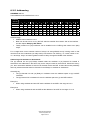
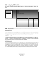
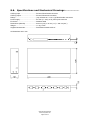
User Manual
Interfaces
Version 02
CUE, a.s., Na Dolinách 6, 147 00 Praha 4, Czech Republic
phone: +420 241 433 555
fax: +420 241 432 446
www.cuesystem.com
e-mail: [email protected]
User Manual Interfaces
UM007_02, 01.04.2003
Copyright © CUE, a.s Praha, Czech Republic 1990 - 2003.
All rights reserved. Specifications are subject to change without prior notice.
Table of Contents
1.
Introduction .................................................................................................................................... 4
1.1.
1.2.
1.3.
1.4.
Overview................................................................................................................................................. 4
Models .................................................................................................................................................... 4
Features ................................................................................................................................................. 4
Programming .......................................................................................................................................... 4
2.
Mounting......................................................................................................................................... 5
3.
System Connection by CUEring................................................................................................... 6
3.1. Overview................................................................................................................................................. 6
3.2. CUEring Connection ............................................................................................................................... 7
3.3. Using O-ring Cable ................................................................................................................................. 8
4.
Power Supply ................................................................................................................................. 9
4.1. Power Input ............................................................................................................................................ 9
4.2. Power consumption ................................................................................................................................ 9
4.3. Fuse........................................................................................................................................................ 9
5.
smartCUE...................................................................................................................................... 10
5.1.
5.2.
5.3.
5.4.
5.5.
5.6.
6.
soundCUE..................................................................................................................................... 21
6.1.
6.2.
6.3.
6.4.
6.5.
6.6.
7.
Overview................................................................................................................................................27
Rear Panel Connections........................................................................................................................27
Front Panel Description .........................................................................................................................29
Diagnostic..............................................................................................................................................30
Specifications and Mechanical Drawings...............................................................................................31
auxCUE ......................................................................................................................................... 32
8.1.
8.2.
8.3.
8.4.
8.5.
8.6.
9.
Overview................................................................................................................................................21
Rear Panel Connections........................................................................................................................22
Front Panel Description .........................................................................................................................23
Setup by DIP Switch ..............................................................................................................................24
Diagnostic..............................................................................................................................................25
Specifications and Mechanical Drawings...............................................................................................26
analogCUE.................................................................................................................................... 27
7.1.
7.2.
7.3.
7.4.
7.5.
8.
Overview................................................................................................................................................10
IR Control - EPROM Preparation...........................................................................................................12
Rear Panel Connections........................................................................................................................13
Front Panel Description .........................................................................................................................17
Diagnostic..............................................................................................................................................19
Specifications and Mechanical Drawings...............................................................................................20
Overview................................................................................................................................................32
Rear Panel Connections........................................................................................................................32
Front Panel Description .........................................................................................................................35
Setup by DIP Switch ..............................................................................................................................37
Diagnostic..............................................................................................................................................37
Specifications and Mechanical Drawings...............................................................................................38
Software and Firmware License................................................................................................. 39
10. Warranty Conditions ................................................................................................................... 40
11. CE Declaration of Conformity..................................................................................................... 41
12. FCC................................................................................................................................................ 42
User Manual Interfaces
www.cuesystem.com
Page 3 of 44
1. Introduction
1.1. Overview ....................................................................
The smartCUE interface is equipped with four serial or IR channels and allows control of devices that
are equipped with infrared, RS-232, RS-422 or RS-485 serial channels. A MIDI version is also
available.
The soundCUE is a fi ve-input / two-output audio matrix switcher capable of switching four stereo
unbalanced line inputs and one mono microphone input to two independently switched outputs. Each
matrix output is composed of two parallel stereo unbalanced line outputs. The soundCUE enables
control of volume, bass and treble independently for each matrix output. The status of the soundCUE
is indicated on the front panel.
The analogCUE is a 32-channel analog output interface. Each independent 0 - 10 V analog output
enables control of VCA, light dimmer, hydraulic or pneumatic valve type devices. The front panel
ncludes LED indicator for each output.
The auxCUE is a 16-channel relay interface capable of switching 16 independent relay outputs, max.
24 V. Switches located on the front panel allow each relay to default in either the open or closed
position. The front panel includes LED indicator for each relay.
1.2. Models........................................................................
Model
Product code
Description
smartCUE
CS0008-R
IR and serial interface
smartCUE
CS0008-M
IR, MIDI and serial interface
soundCUE
CS0009
Audio switcher incl. volume, bass and treble control
analogCUE
CS0004
(32) analog outputs 0 - 10 V
auxCUE
CS0005
(16) relays 24 V
1.3. Features .....................................................................
•
•
•
•
•
•
Full compatibility with Cue’s control units and other interfaces
CUEring data input and output
Channel activity LED indicators on the front panel
Buttons on the front panel
Metal enclosure
Mountable into 19 “ rack, 1 U rack space
1.4. Programming .............................................................
All interfaces are programmed using Cue Director programming tool.
User Manual Interfaces
www.cuesystem.com
Page 4 of 44
2. Mounting
To fix the interface in a 19” rack use supplied accessories Rack Mount Interface Kit 19” fastened on
to both sides of the interface using screws - see picture below.
Interface
top view
(2) screws
for each side
Screws for rack mounting
(not delivered with the interface)
Rack Mount Interface Kit 19"
User Manual Interfaces
www.cuesystem.com
Page 5 of 44
3. System Connection by CUEring
3.1. Overview ....................................................................
All interfaces are connected to the system via CUEring. It is a RS-232 serial channel dedicated for
system commands transmission.
First interface is connected to the control unit Assistant or Assistant-S by CUEring Cable /a. Further
interfaces are connected by Control Cable 9-pin - see picture below.
GND
DC IN
24V
FUSE
1A
CHANNEL D
CHANNEL C
CHANNEL B
CHANNEL A
DATA OUT
DATA IN
CUEring Cable /a
4
3
2
1
Assistant or Assistant-S
CUEring output
Control Cable 9-pin
or
O-ring Cable
MIC
OUTPUTS
INPUTS
GND
DC IN
24V
4
3
2
1
D
C
B
A
DATA OUT
DATA IN
To other interfaces
The connector marked DATA IN is a standard CUEring input. The connector marked DATA OUT is a
standard CUEring output for next interface.
The line driver and bypass relay (when interface is off) are inserted between the DATA IN and the
DATA OUT.
User Manual Interfaces
www.cuesystem.com
Page 6 of 44
3.2. CUEring Connection ....................................................
CUEring IN, DB-9-female connector
5
1
9
6
smartCUE
soundCUE
analogCUE
auxCUE
Pin 1
+ 4.5 V for O-ring
+ 4.5 V for O-ring
+ 4.5 V for O-ring
CUEring OUT, pin 1
Pin 2
Data Out
Data Out
Data Out
Data Out
Pin 3
Data In
Data In
Data In
Data In
Pin 4
CUEring OUT, pin 4
CUEring OUT, pin 4
CUEring OUT, pin 4
CUEring OUT, pin 4
Pin 5
Ground
Ground
Ground
Ground
Pin 6
CUEring OUT, pin 6
CUEring OUT, pin 6
CUEring OUT, pin 6
CUEring OUT, pin 6
Pin 7
CUEring OUT, pin 7
CUEring OUT, pin 7
CUEring OUT, pin 7
CUEring OUT, pin 7
Pin 8
CUEring OUT, pin 8
CUEring OUT, pin 8
CUEring OUT, pin 8
CUEring OUT, pin 8
Pin 9
CUEring OUT, pin 9
CUEring OUT, pin 9
CUEring OUT, pin 9
CUEring OUT, pin 9
CUEring OUT, DB-9-male connector
1
5
6
9
smartCUE
soundCUE
analogCUE
auxCUE
Pin 1
+ 4.5 V for O-ring
+ 4.5 V for O-ring
+ 4.5 V for O-ring
CUEring IN, pin 1
Pin 2
Data In
Data In
Data In
Data In
Pin 3
Data Out
Data Out
Data Out
Data Out
Pin 4
CUEring IN, pin 4
CUEring IN, pin 4
CUEring IN, pin 4
CUEring IN, pin 4
Pin 5
Ground
Ground
Ground
Ground
Pin 6
CUEring IN, pin 6
CUEring IN, pin 6
CUEring IN, pin 6
CUEring IN, pin 6
Pin 7
CUEring IN, pin 7
CUEring IN, pin 7
CUEring IN, pin 7
CUEring IN, pin 7
Pin 8
CUEring IN, pin 8
CUEring IN, pin 8
CUEring IN, pin 8
CUEring IN, pin 8
Pin 9
CUEring IN, pin 9
CUEring IN, pin 9
CUEring IN, pin 9
CUEring IN, pin 9
User Manual Interfaces
www.cuesystem.com
Page 7 of 44
3.3. Using O-ring Cable .....................................................
The Grounds of all interfaces are connected when Control Cable 9-pin is used. Sometimes it is
important to disconnect the "ground loop".
For example
• If smartCUE is used to control presentation software on PC, because the most of PC have
ground connected to power ground.
•
If soundCUE is used for audio control and there are troubles with the noise.
In cases described above it is recommended to replace the Control Cable 9-pin by optically isolated
CUEring cable, type O-ring Cable (CS0106) and to use separated power source (CUEadapter /10W)
for each isolated interface.
Important notes
• O-ring Cable is capable only of one-way communication that means status of Power Express
units cannot be read.
• O-ring cable can be connected to the CUEring output of any interface
• O-ring cable can be connected to the CUEring input of smartCUE, soundCUE, analogCUE
Do not remember the proper grounding of the interface.
User Manual Interfaces
www.cuesystem.com
Page 8 of 44
4. Power Supply
4.1. Power Input ...............................................................
All interfaces are fed via power input 24 V and power supply must be connected to the standard DC
socket marked DC IN 24 V. Recommended power supply units is CUEadapter /10W.
DC IN 24 V, power jack connector
Inner pin
Outer pin
Inner pin
+24 VDC
Outer pin
Ground
4.2. Power consumption....................................................
•
•
•
•
smartCUE
soundCUE
analogCUE
auxCUE
3.5 W
3.5 W
3.5 W
9.0 W
4.3. Fuse ...........................................................................
The fuses in smartCUE, analogCUE and auxCUE are used for the circuitry of the unit electronics. If
the LED indicator marked POWER does not light after power supply 24 V connection, try to replace
this fuse.
User Manual Interfaces
www.cuesystem.com
Page 9 of 44
5. smartCUE
5.1. Overview ....................................................................
The smartCUE interface is equipped with (4) serial (50 to 115 200 bps) or IR channels and allows
control of devices that are equipped with infrared, RS-232, RS-422 or RS-485 serial channels. It is
possible to combine IR and serial control on the channel level that means for example Channel A for
IR control, Channels B to D for serial control.
A MIDI version is also available and must be specified during the order.
The interface smartCUE has the EPROM memory for built-in IR driver library. The data for IR
controlled equipment must be included in smartCUE in the especially dedicated EPROM memory chip.
For more detailed information how to prepare smartCUE for IR operation see bellow.
To connect smartCUE to a device you also need the IR Adapter /s (CS0110) or appropriate Serial IO
Cable /s (CA0110).
An optically isolated O-ring Cable (CS0106) can be used as an option. Sometimes it is important - for
example if smartCUE is used to control presentation software on PC, because the most of PC have
ground connected to 220 VAC ground.
5.1.1. Control Protocols
Although Cue Director programming tool comes with database drivers for most popular devices, there
will always be new equipment for which no protocol is available. In such examples, Cue Library
Director can be used to add new serial or IR commands.
New equipments are continuously being added to the Cue equipment database (filename
Equipmnt.clb) which is installed with Cue Director. If you are unable to find a driver for the particular
equipment please check www.cuesystem.com.
In case that the requested equipment is not in Equipmnt.clb library use Cue Library Director. With the
help of this program you can add new protocol to your library. For other information see Cue Director
manual and help.
User Manual Interfaces
www.cuesystem.com
Page 10 of 44
5.1.2. IR Control
The IR codes are in fact rather long (for example in comparison with serial string commands). The
typical time duration is about 0.5 sec. During the time of transmitting of the IR code the smartCUE can
not accept further requests to send another IR codes. So please let enough time after each IR
command before requesting to send another one from the same smartCUE.
IR General Troubles
• Please pay attention to find proper position for IR Adapter /s. In many rooms exists rather high
IR background signal – it reduces the receiver sensitivity and so reliability of the control.
• No matter how advanced the remote control, some functions can usually only be initiated from
the front panel of the equipment.
• Another potential problem maker is that remotes are supposed to be used interactively, with
the device itself providing feedback to the user. Hence, they often have some toggling
functions, such as power on/off, as well as incremental functions, such as volume up or down,
some Menu select functions. However, as smartCUE has no way of knowing whether the
device is currently on or off, etc., it is possible for the control system to become out of phase
with the device being controlled. Be aware of this when designing control systems based on
IR remote functions.
• In some cases it can be useful to use light sensing device to read LEDs on the equipment to
determine its current status. The Opto-Input Adapter (CS0103) connected to the Assistant or
Assistant-S can be used for such purposes.
5.1.3. Serial Control
Before using the serial control the communication parameters of the serial port must be set. The
setting command must be executed (typically in Autoexec sequence) prior to using any other serial
command.
5.1.4. MIDI Version
The smartCUE version MIDI is adapted to the special communication speed of 31 250 Baud which is
common for MIDI communication. As concerning functions and programming it is compatible with
standard smartCUE. The only difference is in precision of Baud rate generator for standard
communication speeds which are common for RS-232, RS-422 communications. See table below.
Baud Rate
Difference
150
+0.0%
300
+0.0%
600
+0.2%
1 200
+0.2%
2 400
+0.2%
4 800
+0.2%
9 600
-2.4%
19 200
-2.4%
Remark
Theoretically the biggest accessible difference of communication speed should not exceed 4%, but
actual value can be dependent on USART reception algorithm.
User Manual Interfaces
www.cuesystem.com
Page 11 of 44
5.2. IR Control - EPROM Preparation .................................
When using the smartCUE for IR control the data for controlled equipment must be included in
smartCUE in the especially dedicated EPROM memory chip.
Preparation and changing of IR data EPROM
1. Use the Cue Library Director and Teach-In unit to check the functionality of the IR codes
required for the project.
2. In the case of necessity capture new IR codes using the Cue Library Director and
Teach-In unit.
3. Open the interface
• Unscrew (4) screws on the left and on the right side.
• Remove the top covering.
4. Remove EPROM from position U11 in smartCUE - see picture below.
5. Prepare EPROM using Cue Library Director and Teach-In unit.
6. Install the EPROM in position U11 in smartCUE - see picture below.
7. Shut up the interface
• Install the top covering back.
• Screw in (4) screws on the left and on the right side.
CUEring IN
CUEring OUT
Open interface top view
U11
EPROM
User Manual Interfaces
www.cuesystem.com
Page 12 of 44
5.3. Rear Panel Connections..............................................
5.3.1. Overview
All connectors are located on the rear panel - see picture below.
Ground
GND
DC IN
24V
FUSE
1A
Power Supply
24 VDC
CHANNEL D
Fuse
Control Port D
CHANNEL C
Control Port C
CHANNEL B
Control Port B
5.3.2. Power
See chapter Power Supply.
5.3.3. CUEring
See chapter System Connection by CUEring.
User Manual Interfaces
www.cuesystem.com
Page 13 of 44
CHANNEL A
Control Port A
DATA OUT
CUEring
Output
DATA IN
CUEring
Input
5.3.4. Control Ports - IR Control
Pins used for IR control are described in the table below.
CONTROL PORT 1 - 4, (4) DB-9-male connectors
1
5
6
9
Pin 1, 2, 3
Not used
Pin 4
IR output
Pin 5
Ground
Pin 6, 7, 8, 9
Not used
The IR Adapter /s (CS0110) serves as IR signal emitting device. The emitter must be fixed onto
receiving window on the surface of controlled equipment using two sided adhesive tape.
GND
DC IN
24V
FUSE
1A
CHANNEL D
CHANNEL C
CHANNEL B
CHANNEL A
DATA OUT
DATA IN
Controlled Device
IR Adapter /s
Parameters of the cable for IR Adapter /s prolongation are
• Maximal length 70 m using cable 100 pF/m.
• The total cable capacity can be maximal 7 nF.
• The lowest load resistance can be 50 Ω.
• Use 2-core screened cable or twist.
User Manual Interfaces
www.cuesystem.com
Page 14 of 44
IR sensor
Up to (3) IR Adapters /s can be connected in parallel to one IR output.
GND
DC IN
24V
FUSE
1A
CHANNEL D
CHANNEL C
CHANNEL B
IR Adapter /s
CHANNEL A
DATA OUT
DATA IN
IR Adapter /s
IR Adapter /s
Controlled Device 1
IR sensor
Controlled Device 2
IR sensor
Controlled Device 3
IR sensor
In some cases direct cable can be used to provide “direct wired" IR control (like CONTROL-S, …)
instead of IR Adapter /s. In such cases please pay attention to ground loops as the “direct wired" IR
means also galvanic connection.
User Manual Interfaces
www.cuesystem.com
Page 15 of 44
5.3.5. Control Ports - Serial Control
Pins used for serial control RS-232/422/485 are described in the table below.
CONTROL PORT 1 - 4, (4) DB-9-male connectors
1
5
6
9
Pin 1
Not used
Pin 2
Serial data input (data to smartCUE)
Pin 3
Serial data output (data from smartCUE)
Pin 4
DTR output
Pin 5
Ground
Pin 6
DSR input
Pin 7
RTS output
Pin 8
CTS input
Pin 9
Not used
The serial cable can be ordered directly as a Serial IO Cable /s (CA0110) and the controlled
Equipment Name, Type and Manufacturer. For the equipment embedded in the latest Equipmnt.clb
library just this specification is enough, because the Equipment.clb is installed with Cue Director and it
can be checked using Cue Library Director.
For the equipment which is not in the Equipmnt.clb the connector type and pin description including
male / female information is necessary. This information as well as communication protocol is usually
part of the controlled device User Manual.
The serial cable is in many cases part of the accessories of controlled equipment. Usually it is
intended for the direct PC control and it can be used in most cases for smartCUE connection.
GND
DC IN
24V
FUSE
1A
CHANNEL D
CHANNEL C
CHANNEL B
CHANNEL A
DATA OUT
DATA IN
Connector depends
on a controlled device
Controlled Device
Serial IO Cable /s
User Manual Interfaces
www.cuesystem.com
Page 16 of 44
5.4. Front Panel Description ..............................................
5.4.1. Overview
smartCUE
.
DR
AD
456
2 3
9
1
Data
Indicator
N
K
F1
456
F2
F3
F4
A
B
C
S
TE
D
T
ES
R
ET
78
78
0
BA
2 3
.K
1
O
0
9
D
A
AT
S
ES
Address
Selector
Bank
Selector
Function
Buttons
Function
Indicators
Test
Button
Reset
Button
Power Supply
Indicator
5.4.2. Indicators
DATA O.K.
This LED diode is blinking if the interface received correctly the data coming from the CUEring. This
LED blinks OK by Morse after power on, if auto-diagnostic runs correctly.
A, B, C, D
The LED diodes are signaling activity on IR / serial ports. When transmitting IR code, LED indicator
DATA O.K. and respective A, B, C, D indicators are on. If IR code requested from programming is not
in the EPROM, error is indicated by indicator A, B, C or D flashing. Flashing is also stopped if next IR
signal is transmitted OK. When error occurs on serial channel the appropriate LED will start to blink
regularly to make the error indication. This indication will not stop until reset or until the appropriate
button F1 - F4 is pressed or new command was successfully finished.
POWER
Power diode indicates that the interface is powered up.
5.4.3. Buttons
TEST
This button serves for switching over to the testing mode. A detailed description of the testing you can
find in the chapter Diagnostic.
RESET
This button serves for resetting of the interface. During normal operation it is not being used, it solely
serves for testing purposes.
F1, F2, F3, F4
Buttons F1, F2, F3 and F4 serve for reset of errors signalizing for channel 1, 2, 3, 4.
User Manual Interfaces
www.cuesystem.com
Page 17 of 44
5.4.4. Addressing
There can be more smartCUE interfaces in one system. Each of them must be set to a different
combination of address and bank using selectors on the front panel.
ADDRESS selector
Sets address of the interface from 0 to 7. Address identifies interface in the chain.
BANK selector
It serves for bank setting. Default value is 0.
In one bank there can be up to (8) addresses. The ADDRESS from 0 to 7 and the GROUP (BANK)
from 0 to 9 can be set up using the front panel switch selectors.
Address of the port
ADDRESS Selector
CHANNEL A
CHANNEL B
CHANNEL C
CHANNEL D
0
1
2
3
4
1
5
6
7
8
2
9
10
11
12
3
13
14
15
16
4
17
18
19
20
5
21
22
23
24
6
25
26
27
28
7
29
30
31
32
For a usage when not an extreme number of serial or IR ports, BANK = 0 is enough. In that case up to
8 interfaces (4 IR / serial ports each) can be connected to one CUEring, i.e. a total number of serial /
IR channels is 8 x 4 = 32. Only if a greater number of serial / IR channels is needed - change the
BANK of the interface.
Addressing with Assistant or Assistant-S
The serial and IR ports located inside the Assistant or Assistant-S are addressed in the same way as
the ports located in the smartCUE, that means ports in Assistant ot Assistant-S covers the address
space as first two smartCUE interfaces. For example when using Assistant or Assistant-S and
smartCUE in BANK = 0 set the address of smartCUE in the range 2 up to 7. There also exist
possibility select another bank for ports in Assistant or Assistant-S by software.
Important note
When using Cue Configuration Director do not forget to set corresponding address and bank of each
smartCUE also in your project.
User Manual Interfaces
www.cuesystem.com
Page 18 of 44
5.5. Diagnostic ..................................................................
5.5.1. Level 1
After switching on the smartCUE interface the LED DATA O.K. is blinking (with the Morse sign OK)
provided that the auto-diagnostics are in order. The internal microprocessor and basic internal circuits
are being tested. The tests for output line drivers are not included at this level.
5.5.2. Level 2
In the Test Mode the smartCUE is ready for standard operation but it sends out system messages via
DATA IN connector. These system messages help to identify possible problem.
Pressing the TEST and RESET buttons, then release RESET, wait few seconds. Interface smartCUE
transmits via DATA IN serial channel (19200,8,e,2)
• Version of the firmware
• Information about IR interface
• Checksum of the firmware
• System messages are transmitted during IR code transmitting (firmware version dependent)
User Manual Interfaces
www.cuesystem.com
Page 19 of 44
5.6. Specifications and Mechanical Drawings ....................
CUEring input ......................................RS-232, DB-9-female connector
CUEring output ....................................RS-232, DB-9-male connector
IR and serial ........................................(4) control outputs, (4) DB-9-male connectors
Power supply .......................................24 VDC (+/- 20%), 3.5 W, power jack connector
Enclosure ............................................Stainless steel
Dimensions (WxHxD) .........................242 mm (9.5”) x 44 mm (1.7”) x 160 mm (6.3”)
Weight .................................................1.0 kg / 2.7 lb
Supplied accessories ..........................Rack Mount Interface Kit 19”
All dimensions are in mm.
User Manual Interfaces
www.cuesystem.com
Page 20 of 44
6. soundCUE
6.1. Overview ....................................................................
soundCUE is a five-input / two-output audio matrix switcher capable of switching four stereo
unbalanced line inputs and one mono microphone input to two independently switched outputs. Each
matrix output is composed of two parallel stereo unbalanced line outputs. The soundCUE enables
control of volume, bass and treble independently for each matrix output. The status of the soundCUE
is indicated on the front panel.
On the picture below there is the block diagram of the soundCUE.
Input select
0 is microphone
1 - 4 is line
Treble
-15 to +15 dB
Bass
-15 to +15 dB
Channel volume
-38 to 0 dB
Master volume
-68 to +10 dB
OUTPUT 1
Line stereo
MIC
Microphone
INPUT A
Line stereo
INPUT B
Line stereo
INPUT C
Line stereo
INPUT D
Line stereo
Sound Processor 1
Input select
0 is microphone
1 - 4 is line
Treble
-15 to +15 dB
Bass
-15 to +15 dB
OUTPUT 3
Line stereo
Channel volume
-38 to 0 dB
Master volume
-68 to +10 dB
OUTPUT 2
Line stereo
Sound Processor 2
OUTPUT 4
Line stereo
The main features of the soundCUE are
• (2) independent stereo audio processors, each processor has two outputs in parallel
• (1) mono microphone input
• (4) stereo unbalanced line inputs
• Every input can be connected to every audio processor
• Main volume settings -68 to +10 dB for each processor
• Channel level settings -38 to +0 dB for each processor
• Bass settings -15 to +15 dB for each processor
• Treble settings -15 to +15 dB for each processor
User Manual Interfaces
www.cuesystem.com
Page 21 of 44
6.2. Rear Panel Connections..............................................
6.2.1. Overview
All connectors are located on the rear panel - see picture below.
Ground
MIC
OUTPUTS
INPUTS
GND
DC IN
24V
Power Supply
24 VDC
4
3
Microphone
Input
2
1
Line Outputs
1 to 4
D
C
B
Line Inputs
1 to 4
A
DATA OUT
CUEring
Output
DATA IN
CUEring
Input
6.2.2. Power
See chapter Power Supply.
6.2.3. CUEring
See chapter System Connection by CUEring.
6.2.4. Microphone Input
The input marked MIC is a standard microphone input including power supply for electret condenser
microphones. It uses jack 6.3 mm connector
6.2.5. Line Inputs
Inputs marked INPUT A to D are standard stereo line unbalanced audio inputs which use standard
1/4" RCA jack connectors.
6.2.6. Line Outputs
All outputs marked OUTPUT 1 to 4 are stereo line unbalanced audio outputs which use standard 1/4"
RCA jack connectors.
User Manual Interfaces
www.cuesystem.com
Page 22 of 44
6.3. Front Panel Description ..............................................
6.3.1. Overview
soundCUE
O
.K
.
DR
AD
S
ES
O
A
456
B
U
T
1
C
O
D
A
B
U
T
C
2
O
D
A
U
B
T
C
3
O
D
A
B
U
T
C
4
S
TE
D
T
ES
R
ET
2 3
78
0
9
D
A
AT
1
Data
Indicator
Address
Selector
Output 1
Indicators
Output 2
Indicators
Output 3
Indicators
Output 4
Indicators
Test
Button
Reset
Button
Power Supply
Indicator
6.3.2. Indicators
DATA O.K.
This LED diode is blinking if the interface received correctly the data coming from the CUEring. This
LED blinks OK by Morse after power on, if auto-diagnostic runs correctly.
OUT 1 to 4
(4) LEDs for each output indicate selected input. Indication is as described bellow, { means LED no
lights, z means LED lights
{zz{
Microphone input selected
z{{{
Line input A selected
{z{{
Line input B selected
{{z{
Line input C selected
{{{z
Line input D selected
POWER
Power diode indicates that the interface is powered up.
6.3.3. Buttons
TEST
This button serves for switching over to the testing mode. A detailed description of the testing you can
find in the chapter Diagnostic.
RESET
This button serves for resetting of the interface. During normal operation it is not being used, it solely
serves for testing purposes.
User Manual Interfaces
www.cuesystem.com
Page 23 of 44
6.3.4. Addressing
ADDRESS selector
It sets address of the interface from 0 to 7. Address identifies interface in the chain.
Up to (8) soundCUE interfaces can be installed in one system. The address selector identifies
interface by setting it to position 0 to 7. The ADDRESS must be set to different value on each
soundCUE in one system.
Address of
ADDRESS Selector
OUTPUT 1 and 3
OUTPUT 2 and 4
0
1
2
1
3
4
2
5
6
3
7
8
4
9
10
5
11
12
6
13
14
7
15
16
6.4. Setup by DIP Switch...................................................
DIP-8 switch on the bottom side of the interface is not used and it is prepared for the future use.
User Manual Interfaces
www.cuesystem.com
Page 24 of 44
6.5. Diagnostic ..................................................................
6.5.1. Level 1
Level 1 diagnostics runs automatically when the soundCUE is powered on or after reset. It checks
internal microcontroller circuitry. When the tests are running properly then the DATA O.K. LED starts
blinking (by the Morse signal OK). After that the soundCUE is ready for normal operation.
6.5.2. Level 2
Pressing the TEST button when the interface is already powered causes the start of the Level 2
testing.
It sets
• Main volume 0 dB, channel volume 0 dB, bass 0 dB, treble 0 dB
• In period of about 2 seconds starts the testing cycle. In this cycle are all outputs switched to
input A for about 1 second then to B, C, D inputs and to microphone input.
• The cycle will stop when TEST button is released and both sound processors will return to the
same status like before starting level 2.
6.5.3. Level 3
When the TEST button is pressed on while the interface power is switched on or you keep the TEST
and RESET buttons pressed, release the RESET button and keep the TEST button pressed for about
3 seconds. After approx. 3 seconds you can release it.
Connect the diagnostic adapter (connector DB-9-male which makes shortage between pins 2 and 3)
to DATA IN. Now the interface is sending the message itself to DATA OUT, does receive it itself at
DATA IN and carries out the command.
Now the same diagnostic sequence runs
• Main volume 0 dB, channel volume 0 dB, bass 0 dB, treble 0 dB
• In period of about 1 second starts the testing cycle. In this cycle are all outputs switched to
input A for about 2 seconds then to B, C, D and to microphone input.
Level 3 allows check the same functions like level 2 plus the CUEring interfacing circuitry of the
soundCUE.
It can be stopped only by reset.
User Manual Interfaces
www.cuesystem.com
Page 25 of 44
6.6. Specifications and Mechanical Drawings ....................
CUEring input ......................................RS-232, DB-9-female connector
CUEring output ....................................RS-232, DB-9-male connector
Audio inputs.........................................(4) stereo unbalanced line level 0 dB, (8) RCA jack connectors
Microphone input .................................(1) mono microphone, jack 6.3 mm connector
Audio outputs.......................................(2) + (2) unbalanced line level 0 dB, (8) RCA jack connectors
Volume control.....................................-68 to +10 dB
Bass control.........................................-15 to +15 dB
Treble control.......................................-15 to +15 dB
Signal-to-noise ratio.............................Greater than 80 dB
Total harmonic distortion .....................Less than 0.03%
Power supply .......................................24 VDC (+/- 20%), 3.5 W, power jack connector
Enclosure.............................................Metal and stainless steel
Dimensions (WxHxD) ..........................242 mm (9.5”) x 44 mm (1.7”) x 160 mm (6.3”)
Weight..................................................1.1 kg / 2.9 lb
Supplied accessories...........................Rack Mount Interface Kit 19”
All dimensions are in mm.
User Manual Interfaces
www.cuesystem.com
Page 26 of 44
7. analogCUE
7.1. Overview ....................................................................
analogCUE is a 32-channel analog output interface. Each independent 0 - 10 V analog output enables
control of VCA, light dimmer, hydraulic or pneumatic valve type devices. The front panel includes LED
indicator for each output.
7.2. Rear Panel Connections..............................................
7.2.1. Overview
Ground
GND
DC IN
24V
FUSE
1A
Power Supply
24 VDC
OUT 25 - 32
Fuse
Output 25 to 32
OUT 17 - 24
Output 17 to 24
OUT 9 - 16
Output 9 to 16
7.2.2. Power
See chapter Power Supply.
7.2.3. CUEring
See chapter System Connection by CUEring.
User Manual Interfaces
www.cuesystem.com
Page 27 of 44
OUT 1 - 8
Output 1 to 8
DATA OUT
CUEring
Output
DATA IN
CUEring
Input
7.2.4. Control Ports
The analogCUE has (32) outputs 0 - 10 V. All outputs are connected on (4) DB-9-female connectors
marked OUT 1 - 8, OUT 9 - 16, OUT 17 - 24 and OUT 18 - 32. For details see table below.
OUTPUT 1 - 32, (4) DB-9-female connectors
5
1
9
6
Parameters of the analog output
• Range of the output voltage
• Stepping regulation (LSB)
• Min. set-up precision
• Min. overrun period (LSB - MSB)
• Output impedance
OUT 1 - 8
OUT 9 - 16
OUT 17 - 24
OUT 18 - 32
Pin 1
Output 1
Output 9
Output 17
Output 25
Pin 2
Output 2
Output 10
Output 18
Output 26
Pin 3
Output 3
Output 11
Output 19
Output 27
Pin 4
Output 4
Output 12
Output 20
Output 28
Pin 5
Output 5
Output 13
Output 21
Output 29
Pin 6
Output 6
Output 14
Output 22
Output 30
Pin 7
Output 7
Output 15
Output 23
Output 31
Pin 8
Output 8
Output 16
Output 24
Output 32
Pin 9
Ground
Ground
Ground
Ground
0 - 10 V
39 mV
± 0.08 V (± 2 LSB)
0.5 ms
1Ω
When connecting with another device (e.g. dimmer) it is essential to see to a perfect interconnection
with earth. The output voltages generated by the analogCUE are mutually related to the reference
level (ground of the interfaces analogCUE) on pin 9 of the output connectors.
User Manual Interfaces
www.cuesystem.com
Page 28 of 44
7.3. Front Panel Description ..............................................
7.3.1. Overview
analogCUE
O
.K
.
BA
N
K
456
1
2
3
4
5
6
7
8
9
10 11
12 13 14 15
16 17 18 19 20 21 22 23
24 25 26 27 28 29 30 31
32
S
TE
T
ES
R
ET
2 3
78
0
9
D
A
AT
1
Data
Indicator
Address
Selector
Analog Output 1 to 32
Level Indicators
Test
Button
Reset
Button
Power Supply
Indicator
7.3.2. Indicators
DATA O.K.
This LED diode is blinking if the interface received correctly the data coming from the CUEring. This
LED blinks OK by Morse after power on, if auto-diagnostic runs correctly.
POWER
Power diode indicates that the interface is powered up.
OUTPUT 1 to 32
During normal operation these LED are lighting up if the output voltage is higher than 50% (5.0 V) of
the maximum, they go out when the output voltage is lower that 50% (5.0 V) of the maximum.
7.3.3. Buttons
TEST
This button serves for switching over to the testing mode. A detailed description of the testing you can
find in the chapter Diagnostic.
RESET
This button serves for resetting of the interface. During normal operation it is not being used, it solely
serves for testing purposes.
User Manual Interfaces
www.cuesystem.com
Page 29 of 44
7.3.4. Addressing
BANK selector
It serves for bank setting. Default value is 0. Onto one CUEring there can be connected more than one
analogCUE interface. Each of them must have different BANK setting.
There can be up to (320) analog output ports in one system hence a maximum of (10) analogCUE
interfaces on one CUEring. The BANK from 0 to 9 can be set up using the front panel switch. The
different value of bank must be set to each analogCUE in one system.
Addressing with Assistant or Assistant-S
The analog output ports located inside the Assistant or Assistant-S are addressed in the same way as
the analog output ports located in the analogCUE. The default bank for analog output ports located
inside the Assistant or Assistant-S is 0. Should this annoy you, then switch over the BANK switch at
the analogCUE to value from 1 to 9. Or there also exist possibility select by software another bank for
analog output ports in Assistant or Assistant-S.
7.4. Diagnostic ..................................................................
7.4.1. Level 1
After switching on the analogCUE the LED DATA O.K. (with the Morse sign OK) is blinking provided
that the auto-diagnostics are in order. The internal microprocessor and the output circuits are being
tested.
7.4.2. Level 2
As long as you keep the button TEST pressed all outputs are set on 100%.
7.4.3. Level 3
When you connect the testing adapter (connector DB-9-male which makes shortage between pins 2
and 3) to the DATA IN connector you have to keep the button TEST pressed after power on. This way
you can set the analogCUE to the testing mode. The interface analogCUE is then transmitting itself
the message, receives the message in the testing device, evaluates and executes it. The diodes are
signaling in the same way as with the diagnostics Level 2.
User Manual Interfaces
www.cuesystem.com
Page 30 of 44
7.5. Specifications and Mechanical Drawings...................
CUEring input ......................................RS-232, DB-9-female connector
CUEring output ....................................RS-232, DB-9-male connector
Analog..................................................(32) outputs 0 - 10 V max. 5 mA, (4) DB-9-female connectors
Power supply .......................................24 VDC (+/- 20%), 3.5 W, power jack connector
Enclosure.............................................Stainless steel
Dimensions (WxHxD) ..........................242 mm (9.5”) x 44 mm (1.7”) x 160 mm (6.3”)
Weight..................................................1.0 kg / 2.7 lb
Supplied accessories...........................Rack Mount Interface Kit 19”
All dimensions are in mm.
User Manual Interfaces
www.cuesystem.com
Page 31 of 44
8. auxCUE
8.1. Overview ....................................................................
auxCUE is a 16-channel relay interface capable of switching 16 independent relay outputs,
max. 24 V / 0.5 A. DIP switches located on the front panel allow each relay to default in either the
open or closed position. The front panel includes LED indicator for each relay.
The main features of the auxCUE are
• (16) closures 24 V / 0.5 A
• Normal open (NO) or normal close (NC) operation for each relay independently
• Pull-up resistors connected to +15 VDC for each relay
8.2. Rear Panel Connections..............................................
8.2.1. Overview
Ground
GND
DC IN
24V
FUSE
1A
Power Supply
24 VDC
AUX 13 - 16
Fuse
Relay 13 to 16
AUX 9 - 12
Relay 9 to 12
AUX 5 - 8
Relay 5 to 8
8.2.2. Power
See chapter Power Supply.
8.2.3. CUEring
See chapter System Connection by CUEring.
User Manual Interfaces
www.cuesystem.com
Page 32 of 44
AUX 1 - 4
Relay 1 to 4
DATA OUT
CUEring
Output
DATA IN
CUEring
Input
8.2.4. Control Ports
The auxCUE has (16) relay outputs. Each relay can be set to Normal Close (NC) or to Normal Open
(NO) mode by switches on the front panel. Pull-up resistors connected to +15 VDC are switched by
DIP switches located on the bottom panel.
For better understanding of the relay and switches connection see picture below.
+15 VDC
Resistor
1.5 kohm
DIP switch
Relay
OFF
Front panel switch
NC
Relay in
Relay out
pin 6, 7, 8, 9
pin 1, 2, 4, 5
ON
NO
Ground
pin 3
All relays are connected on (4) DB-9-female connectors marked RELAY 1 - 8, RELAY 9 - 16, RELAY
17 - 24 and RELAY 18 - 32. For details see table below.
AUXILIARY 1 - 16, (4) DB-9-female connectors
5
1
9
6
AUX 1 - 4
AUX 5 - 8
AUX 9 - 12
AUX 13 - 16
Pin 1
Relay 1 out
Relay 5 out
Relay 9 out
Relay 13 out
Pin 2
Relay 2 out
Relay 6 out
Relay 10 out
Relay 14 out
Pin 3
Ground
Ground
Ground
Ground
Pin 4
Relay 3 out
Relay 7 out
Relay 11 out
Relay 15 out
Pin 5
Relay 4 out
Relay 8 out
Relay 12 out
Relay 16 out
Pin 6
Relay 1 in
Relay 5 in
Relay 9 in
Relay 13 in
Pin 7
Relay 2 in
Relay 6 in
Relay 10 in
Relay 14 in
Pin 8
Relay 3 in
Relay 7 in
Relay 11 in
Relay 15 in
Pin 9
Relay 4 in
Relay 8 in
Relay 12 in
Relay 16 in
User Manual Interfaces
www.cuesystem.com
Page 33 of 44
DIP switches for pull-up resistors are located on the bottom side of the auxCUE - see picture below.
Interface bottom view
DIP Switch 1
DIP Switch 2
ON
12345678
DIP Switch 3
DIP Switch 4
CUEring IN
ON
ON
ON
ON
1234
1234
1234
1234
CUEring OUT
In the table below you can see relation between DIP switches and pull-up resistors.
Switch view
ON
1234
Switch nr.
DIP Switch 1
DIP Switch 2
DIP Switch 3
DIP Switch 4
1
Pull-up relay 1 ON
Pull-up relay 5 ON
Pull-up relay 9 ON
Pull-up relay 13 ON
2
Pull-up relay 2 ON
Pull-up relay 6 ON
Pull-up relay 10 ON
Pull-up relay 14 ON
3
Pull-up relay 3 ON
Pull-up relay 7 ON
Pull-up relay 11 ON
Pull-up relay 15 ON
4
Pull-up relay 4 ON
Pull-up relay 8 ON
Pull-up relay 12 ON
Pull-up relay 16 ON
User Manual Interfaces
www.cuesystem.com
Page 34 of 44
8.3. Front Panel Description ..............................................
8.3.1. Overview
auxCUE
O
.K
.
DR
AD
1
2
3
4
5
6
7
8
9
456
10 11
12 13 14 15 16
1 2 3 4 5 6 7 8 9 1 0 11 1 2 1 3 14 1 5 1 6
ST
X X X X X X X X X X X X X X X X
TE
AU AU AU A U AU AU A U A U AU AU AU AU A U AU AU AU
ES
R
ET
2 3
78
0
9
D
A
AT
S
ES
1
.
.C
N
Data
Indicator
Address
Selector
Relay 1 to 16
Test and Normal Open / Normal Close Switches
Relay 1 to 16
On / Off Indicators
Test
Button
Reset
Button
Power Supply
Indicator
8.3.2. Indicators
DATA O.K.
This LED diode is blinking if the interface received correctly the data coming from the CUEring. This
LED blinks OK by Morse after power on, if auto-diagnostic runs correctly.
POWER
Power diode indicates that the interface is powered up.
8.3.3. Buttons
TEST
This button serves for switching over to the testing mode. A detailed description of the testing you can
find in the chapter Diagnostic.
RESET
This button serves for resetting of the interface. During normal operation it is not being used, it solely
serves for testing purposes.
8.3.4. Switches
SWITCH 1 to 16
The switches NO / NC marked 1 to 16 allow to connect NC or NO contact to relay output pin on the
output connector separately for each relay - see relay functional diagram.
• Switch position UP - Normal Open Mode
• Switch position DOWN - Normal Close Mode
By changing over the position of the switches always the position of the output is changing, so you can
use this switches to test connected devices.
User Manual Interfaces
www.cuesystem.com
Page 35 of 44
8.3.5. Addressing
ADDRESS selector
It sets address of the interface from 0 to 5.
ADDRESS
Selector
Address of AUX
1
2
3
4
5
6
7
8
9
10
11
12
13
14
15
16
0
1
2
3
4
5
6
7
8
9
10
11
12
13
14
15
16
1
17
18
19
20
21
22
23
24
25
26
27
28
29
30
31
32
2
33
34
35
36
37
38
39
40
41
42
43
44
45
46
47
48
3
49
50
51
52
53
54
55
56
57
58
59
60
61
62
63
64
4
65
66
67
68
69
70
71
72
73
74
75
76
77
78
79
80
5
81
82
83
84
85
86
87
88
89
90
91
92
93
94
95
96
Address range
• Address can be set from 0 to 5
• Bank can be set from 0 to 8 by the DIP switch accessible from bottom side of the interface see the chapter Setup by DIP Switch.
• Totally maximum of (54) interfaces can be installed on the CUEring that means max. (864)
relays.
For a usage when not an extreme number of relays it is enough BANK 0 only is being used. In that
case there can be 6 interfaces (16 relays each) connected to one CUEring, i.e. a total number of 6 ×
16 = 96 relays. Only if we need a greater number of relays change the BANK of the interface.
Addressing with Assistant or Assistant-S
The (8) General I/O and (16) Relays located inside the Assistant or (8) General I/O located in
Assistant-S are addressed in the same way as the relays located in the auxCUE. Should this annoy
you, then use another address or switch over the bank at the auxCUE. Or there also exists possibility
select by software another bank for General I/O and Relays in Assistant or Assistant-S.
Generally say
• The (8) General I/O and (16) Relays in Assistant cover the address space as (2) auxCUE
interfaces.
• The (8) General I/O in Assistant-S cover the address space as (1) auxCUE interface.
Example 1
• When using Assistant and auxCUE set the address of auxCUE in the range of 2 to 5.
Example 2
• When using Assistant-S and auxCUE set the address of auxCUE in the range of 1 to 5.
User Manual Interfaces
www.cuesystem.com
Page 36 of 44
8.4. Setup by DIP Switch...................................................
DIP-8 switch is located on the bottom side of the interface. It serves for BANK settings - see the table
below.
Switch view
ON
12345678
Switch nr.
Function
1
Not used
2
Not used
3
Not used
4
OFF for standard operation
5
OFF for standard operation
6
BANK bit 2
7
BANK bit 1
8
BANK bit 0
BANK
Switch 6
Switch 7
Switch 8
0
OFF
OFF
OFF
1
OFF
OFF
ON
2
OFF
ON
OFF
3
OFF
ON
ON
4
ON
OFF
OFF
5
ON
OFF
ON
6
ON
ON
OFF
7
ON
ON
ON
8.5. Diagnostic ..................................................................
8.5.1. Level 1
Level 1 diagnostics runs automatically when the auxCUE is powered on or after reset. It checks
internal microcontroller circuitry. When the tests are running correctly then the DATA O.K. LED starts
blinking (by the Morse signal OK). After that the auxCUE is ready for normal operation.
8.5.2. Level 2
If you keep pressed TEST button, then the testing cycle is operating automatically for all relays. The
processor in the loop is successively switching on all relays, the number of the simultaneously
switched on relays depends on the position of the switch ADDRESS.
8.5.3. Level 3
If you connect the testing adapter (connector DB-9-male which makes shortage between pins 2 and 3)
to the connector DATA IN, you keep the button TEST pressed and then release RESET button. The
auxCUE interface sends the message itself, receives the message via the interconnection in the
testing adapter evaluates and executes it out (successive switching on of all relays). The switching
over into the operating mode is done by pressing button RESET or switching off and on the power.
User Manual Interfaces
www.cuesystem.com
Page 37 of 44
8.6. Specifications and Mechanical Drawings...................
CUEring input ......................................RS-232, DB-9-female connector
CUEring output ....................................RS-232, DB-9-male connector
Relays..................................................(16) closures 24 V / 0.5 A, (4) DB-9-female connectors
Power supply .......................................24 VDC (+/- 20%), 9 W, power jack connector
Enclosure.............................................Stainless steel
Dimensions (WxHxD) ..........................242 mm (9.5”) x 44 mm (1.7”) x 160 mm (6.3”)
Weight..................................................1.2 kg / 3.2 lb
Supplied accessories...........................Rack Mount Interface Kit 19”
All dimensions are in mm.
User Manual Interfaces
www.cuesystem.com
Page 38 of 44
9.
Software and Firmware License
END-USER NOTICE AND LICENSE AGREEMENT FROM CUE, spol. s r.o.
NOTICE TO END-USER
CAREFULLY READ THE FOLLOWING LEGAL AGREEMENT (THIS "LICENSE"). INSTALLATION OR USE OF THE
ENCLOSED CUE, spol. s r.o. SOFTWARE PROGRAMS (COLLECTIVELY, "SOFTWARE") ON YOUR COMPUTER
SYSTEMS OR HARDWARE DEVICES CONSTITUTES YOUR ACCEPTANCE OF THESE TERMS. IF YOU DO NOT AGREE
TO THE TERMS OF THIS LICENSE, PROMPTLY DELETE THE SOFTWARE FROM YOUR COMPUTER SYSTEMS AND
HARDWARE DEVICES, DESTROY ANY COPIES YOU MADE OF THE SOFTWARE OR ANY INSTALLATION MEDIA OF THE
SOFTWARE INCLUDED WITH YOUR SYSTEM, AND DISPOSE OF ALL WRITTEN MATERIALS IN YOUR POSSESSION
REGARDING THE SOFTWARE.
License Grant
CUE grants to You, as an individual, a license to install and use one (1) copy of the Software on a single computer at a time;
provided, however, that You may make copies of the Software solely for Your development of applications for CUE hardware
and demonstration versions of such applications. Any applications created with the Software may only be used with Cue
hardware. Your license to use the Software is conditioned upon Your compliance with the terms of this License. A License is
required for each end-user of the Software. A license is required for each installation of the Software. You may make one (1)
copy of the Software for archival purposes only. You may use this Software only in connection with CUE hardware. You must
have acquired the Software directly in connection with the purchase of CUE hardware from CUE or from a CUE approved
reseller for this license to be effective. If You have purchased a Site License, You may complete only the number of
installations specified in the License Agreement accompanying the Software.
Copyright
The Software and software built into CUE hardware ("Firmware") are protected by copyright law and international treaty
provisions. You acknowledge that no title to the intellectual property in the Software and Firmware is transferred to You. You
further acknowledge that title and full ownership rights to the Software and Firmware will remain the exclusive property of CUE,
and You will not acquire any rights to the Software and Firmware except as expressly set forth in this License. You agree that
any copies of the Software will contain the same proprietary notices which appear on and in the Software.
Prohibited Uses
Without obtaining prior written permission from CUE, You may not (a.) use, copy, modify, alter, or transfer the Software or
documentation except as expressly provided in this License; (b.) translate, disassemble, decompile, reverse program or
otherwise reverse engineer the Software and Firmware; (c.) sublicense or lease the Software or its documentation (d.) use this
Software with any hardware other than products produced by CUE or in connection with applications being developed for CUE
hardware; or (e.) use the Software in a multi-user, network, or multiple computer environment or in a rental, time sharing or
computer service business. Without prejudice to any other rights, CUE may terminate this License if You fail to comply with its
terms and conditions. In such event, You must immediately destroy all copies of the Software.
No Other Warranties
CUE DOES NOT WARRANT THAT THE SOFTWARE AND FIRMWARE IS ERROR FREE. CUE DISCLAIMS ALL
WARRANTIES WITH RESPECT TO THE SOFTWARE AND FIRMWARE, EITHER EXPRESS OR IMPLIED, INCLUDING BUT
NOT LIMITED TO IMPLIED WARRANTIES OF MERCHANTABILITY, FITNESS FOR A PARTICULAR PURPOSE AND
NONINFRINGEMENT OF THIRD PARTY RIGHTS. SOME JURISDICTIONS DO NOT ALLOW THE EXCLUSION OF IMPLIED
WARRANTIES OR LIMITATIONS OF HOW LONG AN IMPLIED WARRANTY MAY LAST, OR THE EXCLUSION OF
LIMITATION OF INCIDENTAL DAMAGES, SO THE ABOVE LIMITATIONS OR EXCLUSIONS MAY NOT APPLY TO YOU.
THIS WARRANTY GIVES YOU SPECIFIC LEGAL RIGHTS AND YOU MAY ALSO HAVE OTHER RIGHTS WHICH VARY
FROM JURISDICTION TO JURISDICTION.
No Liability for Consequential Damages
IN NO EVENT SHALL CUE BE LIABLE TO YOU FOR ANY CONSEQUENTIAL, SPECIAL, INCIDENTAL, OR INDIRECT
DAMAGES OF ANY KIND ARISING OUT OF THE PERFORMANCE OR USE OF THE SOFTWARE, EVEN IF CUE HAS BEEN
ADVISED OF THE POSSIBILITY OF SUCH DAMAGES.
Label on Hardware
Use of this hardware and the software programs controlling this hardware is subject to the terms of the Software and Hardware
License Agreements (the “License Agreements”). You should not use the software and hardware until you have read the
License Agreements. By using the software and hardware, you signify that you have read the Licenses Agreements and accept
their terms. The “License Agreement” is available at www.cuesystem.com.
Trademark Notice
CUE and the CUE logo are trademarks of CUE spol. s r.o. in the United States and in other countries.
User Manual Interfaces
www.cuesystem.com
Page 39 of 44
10. Warranty Conditions
Warranty Duration
CUE provides warranty for all CUE products for a period of 3 years from the day of purchase. The provided warranty for touch
screens is 2 years from the day of purchase. CUE accepts reclamation of 5 not properly working dots and more (2 dots join – 1
counts). The warranty provided for rechargeable accumulators is 6 months from the day of purchase
Liability
CUE is not liable for any consequential damage caused by CUE products including any loss of profits, incidental or
consequential damages or any claims made by a third parties.
General Warranty Terms
a)
b)
c)
d)
CUE warrants that its products are without defects in material and are fully functional for the duration of the warranty.
Warranty repairs are free of charge. The customer will send the damaged device to CUE at his cost.
All warranty repairs and after warranty services are made at CUE premises. It is strictly prohibited to repair CUE
products or to change any accessory parts, except those parts with limited service life. CUE is not liable for
consumables or parts with limited service life (lamps, batteries etc.)
The warranty further does not apply to the following cases
•
Damages caused by operating the system not according to the conditions defined in user manual or
instruction (wrong power supply voltage, operation outside deferred temperature range, operation in humid
environment and mechanical damages).
•
Damages caused by faulty service, maintenance, connection, and use of other than original connection
cable.
•
Damage caused by agencies i.e. incidental or unpredictable impacts (fire, earthquake, flood, thunder,
strong electric induction, water, strong wind, theft, vandalism etc.)
After Warranty Services
a)
b)
c)
All warranty repairs are normally on a ‘back to base’ basis, as defined in 3 c)
All out warranty repair costs will be fully charged to the customer.
In cases where our staff are called out to assist, cost of transport and time will be at customer cost
User Manual Interfaces
www.cuesystem.com
Page 40 of 44
11. CE Declaration of Conformity
We, the producer
CUE spol. s r. o., Na Dolinách 6, Praha 4, Czech Republic
acknowledge our sole responsibility, that the product incl. accessories
Kind of equipment
Remote Control System
Type designation
CS0197 touchCUE-L 99, CS0159 touchCUE 99, CS0157 touchCUE-S 99,
CS0183 touchCUE-V, CS0198 touchCUE-L, CS0200 touchCUE-M, CS0176 touchCUE-MM, CS0122 touchCUE,
CS0142 touchCUE-S,
CS0178 touchCUE-V /t, CS0199 touchCUE-L /t, CS0204 touchCUE-M /t, CS0143 touchCUE-S /t,
CS0158 touchCUE-S /w,
CS0224 touchCUE-S /d,
CS0205 touchCUE-M /r, CS0144 touchCUE-S /r
ST0007 Guide, CS0188 touchCUE-SRF, CS0171 rfbaseCUE,
ST0013 monitorCUE-V, CS0203 monitorCUE, CS0190 touchCUE-V /i, CS0151 PC Interface 485
CS0170 rfCUE 99, CS0170 rfCUE 99, CS0149 irCUE 99, CS0133 irCUE, CS0080 irCUE Receiver,
CS0169 irCUE Receiver 485,
CS0221 keypadCUE-1G, CS0222 keypadCUE-2G, CS0223 keypadCUE-3G,
CS0145 keyboardCUE 99, CS0128 keyboardCUE, CS0174 keyboardCUE-S, CS0129 keyboardCUE /t,
CS0146 keyboardCUE-S /w, CS0130 keyboardCUE /r, CS0191 inputCUE,
CS0173 eCUE
CS0051 Assistant, CS0150 Assistant-S, CS0100 PC Card, CS0227 CUEwire Splitter,
CS0008 smartCUE, CS0201 sbiCUE-DMX, CS0009 soundCUE, CS0004 analogCUE, CS0005 auxCUE,
CS0165 PED202, CS0166 PEF200, CS0167 PER610, CS0163 PEC25, CS0225 PEA208, CS0164 PED108,
CS0184 CUEadapter /10W, CS0226 CUEadapter /20W, CS0185 CUEadapter /50W, CS0186 CUEadapter /80W,
CS0168 PES03, CS0016 powerAUX,
PT0005 Cue Director, PT0004 Teach-In, PT0006 WinKit
in accordance with EMC Directive 89/336/EEC,
is in compliance with the following norms or documents:
EN50082-1 (IEC801-2), IEC65(CO)39, DIN VDE 0839 part 82-1, DIN VDE 0843 part 4, IEC801-4,
EN50081-1 EN55022 class B, DIN VDE 0839 part 81-1, EN55014, EN55011.
Jaroslav Dibitanzl
Member of Board of Directors
User Manual Interfaces
www.cuesystem.com
Page 41 of 44
12. FCC
Caution
Changes or modifications to this unit not expressly approved by the party responsible for compliance could void the user's
authority to operate the equipment.
Note
This equipment has been tested and found to comply with the limits for a Class B digital device, pursuant to Part 15 of the FCC
Rules. These limits are designed to provide reasonable protection against harmful interference in a residential installation. This
equipment generates, uses and can radiate radio frequency energy and, if not installed and used in accordance with the
instructions, may cause harmful interference to radio communications. However, there is no guarantee that interference will not
occur in a particular installation. If this equipment does cause harmful interference to radio or television reception, which can be
determined by turning the equipment off and on, the user is encouraged to try to correct the interference by one or more of the
following measures:
•
Reorient or relocate the receiving antenna.
•
Increase the separation between the equipment and receiver.
•
Connect the equipment into an outlet on a circuit different from that to which the receiver is connected.
•
Consult the dealer or an experienced radio / TV technician for help.
User Manual Interfaces
www.cuesystem.com
Page 42 of 44
Notes
User Manual Interfaces
www.cuesystem.com
Page 43 of 44
Notes
User Manual Interfaces
www.cuesystem.com
Page 44 of 44