1
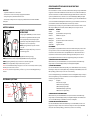
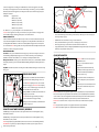
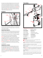
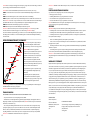
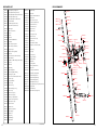
before attempting to un-jam the marker. Remove all paintballs and the loader from the feed neck. Have the barrel
removed from the receiver to allow the paintball(s) to exit. With enough force tension on the Cocking Knob, pull
back to release the Delrin bolt from the jammed position. Another method is to use a “Straight Shot Squeegee” or
the end of a wood dowel rod; push against the face of the Delrin bolt with enough force to release the jammed bolt.
Always clean the paint from the breach and barrel to enhance the performance of your marker. IMPORTANT: Never
look down the barrel of the marker when loaded or unloaded. Remove the attached Compressed Air Tank before
attempting to un-jam the Delrin Bolt. NOTE: Never use a metal rod or screwdriver as a tool to push on the Delrin
bolt, anything metal will scratch and damage the inside of the marker.
CUP SEAL REMOVAL
#STK001 #STP021
#ITP002
#REC021
#ITP001
#SCR007
#WRH006
#VRT001
ANTI CHOP EYES
#SCR004
#ITP003
#BLS002
#SCR008
#SCR001
#SPR002
#SCR001
#BLS021
#WRH006
#SCR002
#REG001
#TRF002
The Anti Chop Eyes help prevent the chopping of paint by not allowing the marker to fire until a paintball is properly
chambered in the breach. The Eyes transmit a beam across the inside of the breech. The circuit board is preset from
the factory and does not need to be adjusted or altered. (If the Eyes are ON and do not see each other when firing
your marker, you will have to clean the Eyes.)
CLEANING THE ANTI CHOP EYES
Using a squeegee or swab thru the breech should clean the Eyes enough for the Eyes to detect each other. Another
way is to use an aerosol can of air thru the breech to remove any paint or dirt. To thoroughly clean the Eyes using
the supplied Allen wrench remove both Eye Panel Screws (#SCR004) and Eye Panels (#BLS021). Once the Eye
Panel Screws & Eye Panels are removed, proceed with a soft pinch to remove the Eye Wire Harness (#WRH006)
from the receiver. Use a cloth or paper towel to remove any paint or dirt that is blocking the Eyes.
IMPORTANT: Cleaning the Eyes often will help reduce dirt, paint or oil residue that blocks the Eyes.
NOTE: Never attempt to rush the cleaning process or you can pinch the wires and cause the marker to malfunction
with the Eye Mode ON. Take precaution not to over tighten the Eye Panel Screws or this can lead to stripping
the head. NOTE: When the Eye Panels are removed the Ball Stopper(s) (#BLS002) may be attached to the Eye
Panels and can cause them to fall out. HELPFUL TIP: Please note how the parts are removed for easy reassembly.
IMPORTANT: Before removing both Eye Panels use a needle or dental pick thru the hole of the Eye Panel to
remove any dirt that can build up and block the Allen screw from loosing. It’s possible if the dirt is not removed you
can strip the Eye Panel Screw.
CHANGING THE BALL STOPPERS
Experiencing paint rolling through the barrel can be related to small diameter paintball(s) or the loss of a Ball
Stopper(s) (#BLS002). When removing Eye Panel Screws (#SCR004) and Eye Panels (#BLS021) the Ball
Stopper(s) will be accessible for cleaning or replacement. HELPFUL TIP: Please note how the parts are removed
for easy reassembly. IMPORTANT: Before removing both Eye Panels use a needle or dental pick thru the hole of
the Eye Panel to remove any dirt that can build up and block the Allen screw from loosing. It’s possible if the dirt is
not removed you can stripe the Eye Panel Screw. NOTE: Take precaution not to over tighten the Eye Panel Screws
or this can strip the head.
11
Part Names and Part Numbers describe in this selection:
Cup Seal (#ITP001)
Trigger Frame Screw (#SCR001)
Valve Spring (#SPR002)
M4x8 Head Screw (#SCR002)
Inline Regulator (#REG001)
Receiver (#REC021)
Trigger Frame (#TRF002) Valve Body (#ITP003)
Vertical Screw (#SCR008)
*9.6 Rechargeable Battery (#JE1015)
Eye Wire Harness (#WRH006)
*Velocity Adjuster & Spring Guide (#VTA021)
Valve Body Screw (#SCR007)
*Delrin Bolt (#VBT001)
Striker Plug (#STP021)
*Striker Spring (#SPR001) Top Cocking Knob (#STK001)
*Striker Bolt Mini (#STB001)
Valve Pin (#ITP002)
*Striker Buffer (#STF001)
Vertical Adapter w/Gauge (#VRT001) *parts not shown
STEP BY STEP
WARNING: Never at any time should you attempt to unscrew the Vertical Regulator while the
marker is pressurized. Doing so can cause serious injury or death.
HELPFUL TIP: The sign of a worn Cup Seal is the presence of Compressed Air leaking down the barrel.
STEP 1 Twist the Inline Regulator counter-clockwise to release off the Vertical Adapter w/Gauge. The
hose line will hold the Inline Regulator when it dangles from the C/A On/Off.
STEP 2 Remove all three M4x8 Screws on the left side of the Trigger Frame. The Grip Panels will allow
access to the Circuit Board.
STEP 3 Gently detach the Eye Wire Harness from the Circuit Board. This will allow maneuvering around
certain parts. HELPFUL TIP: Gently move aside the Rechargeable Battery out of the Trigger Frame to
view the Eye Wire Harness. Gently remove the Eye Wire Harness thru the coil set channel exiting thru
the top of the Trigger Frame.
STEP 4 Remove both Trigger Frame Screws. This will then allow the Trigger Frame to disconnect from
the Receiver. Pull upward on the Top Cocking Knob to allow the Delrin Bolt to release from the Striker
Bolt Mini. Once the Striker Plug has been removed the Striker Spring, Striker Buffer and Striker Bolt
Mini need to be removed out the rear of the Receiver.
12