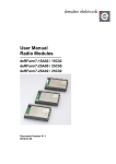
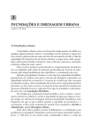
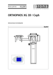
1
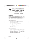
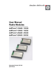
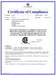
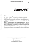
QROlle II - Users manual
Incl. CPU programming and rig control
Content
1 Introduction.................................................................................................................2
2 Front panel...................................................................................................................3
2.1 LCD Display information.....................................................................................3
2.1.1 Frequency......................................................................................................3
2.1.2 Settings display.............................................................................................3
2.2 Buttons and controls.............................................................................................3
2.2.1 Main functions (quick press!)- Left to right..................................................4
2.2.2 Sub functions - left to right...........................................................................4
2.2.3 Main dial.......................................................................................................5
2.3 Tune-feature.........................................................................................................5
2.4 Menu mode...........................................................................................................5
2.4.1 Menu items: ..................................................................................................5
3 Back panel ..................................................................................................................6
3.1 Pin out on the connectors.....................................................................................6
4 Serial interfacing to QROlle II....................................................................................7
4.1 RS232-port for software upload to CPU..............................................................7
4.1.1 Installation process - serial............................................................................7
4.2 RS232-port for control of QROlle.......................................................................9
4.3 Using the USB-interface for a PC Virtual COM port..........................................9
5 Transverter interfacing................................................................................................9
6 Appendix A: Hardware modification for Display mode...........................................10
Nov 24 2009 - Author: SM0JZT Tilman
QROlle II - Users manual, sw ver 4x
Page 1(10)
QROlle II - Users manual
1 Introduction
The QROlle II is a home-brew 6 band shortwave QRP-transceiver.
The bands covered are 17, 20, 30, 40, 80 and 160 meters. Transverter use is possible
for other bands.
The modes are CW and SSB with output power of 10W.
The rig is controlled by a CPU and can also be controlled remotely through a serial
RS232 and/or USB interface. The CPU is an ATMEL ARM processor with software
that can be updated on the board through JTAG or the serial interfaces.
The designer of the analogue part is SM6DJH Olof Holmstrand and for the digital part
SM5DEH Nils Söderman. Work has been under way starting around 2007 after the
closing down of the first QROlle–project.
The project is the result of close cooperation between SM0JZT Tilman D. Thulesius
and the designers.
SM4DHN Lars-Bertil Karlsson and SM4OUX Lars Olsson provide shipments of kits.
The Analogue part is on two separate boards (called A and B) that are sandwiched
together around an aluminium sheet that doubles as a cooling media for the voltage
regulator and RF output transistor. A separate board called C consists of the DDS
circuit and interfacing circuitry between the analogue and digital boards.
Finally the digital board (called D) is mounted behind the front panel and holds the
CPU, supporting circuitry, digital LCD display, various buttons and a knob for the
user interface.
All of the electronics mentioned above are described in separate documentation, so
only mentioned briefly here.
QROlle II - Users manual, sw ver 4x
Page 2(10)
2 Front panel
The front panel is the main users interface. The QROlle II is controlled by a
microprocessor that sits behind the front panel. The user interface is a LCD-display
and a number of buttons, all controlled by software. So the user interface may be
changed with the software.
2.1 LCD Display information
The display used is a 20 x 2 character backlit standard component. Information given
is presented, fully software controlled.
2.1.1 Frequency
Alternative
First row
Standard display
Split
RIT
A 7000.00 (rx/tx) A 7000.00 (rx)
A 7000.00
Second row B 7010.00
S 7010.00 (tx)
Rit -/+ .102Hz
The displayed frequency is given in the alternatives above.
The standard display show the set frequency for the VFO:s A and B. Here it is always
the VFO in the first row that is the one used for reception and transmission.
The software remembers the mode and filter used for each band and VFO. A nice
feature is that you can for example use the B-VFO for CW on the lower part of a band
and A-VFO for SSB. This way you can quickly move from SSB to CW-QSO:s in a
band.
When the rig is set in “Split mode” the frequency given in first row is for reception
and the one in second row for transmission.
When the rig is in “RIT mode” the offset (+ or -) is given in the second row.
2.1.2 Settings display
Up in the right hand corner S-meter level and power output is given in a bar graph.
In the right hand part of the second row status settings are given for:
• Filter used – Wide or Narrow
• Pre Amplifier – P on or off
• Mode setting – LSB, USB or CW
• Speech Compressor - C on or off
2.2 Buttons and controls
The front panel as 8 push buttons and one encoder dial with a push button function.
QROlle II - Users manual, sw ver 4x
Page 3(10)
To the right of the LCD display there is a dual colour LED to display reception and
transmission status:
Green for reception and yellowish for transmission
A red colour indicates a CPU error.
The push buttons, having dual functions, controls the software.
A quick press of a button will function given above the buttons.
A longer press, more than half a second, of a button will give the function given
below the buttons.
2.2.1 Main functions (quick press!)- Left to right
•
•
•
•
•
•
•
•
FLTR – Toggle of LF filter used. The one used is presented in display with
Wide or Narrow
PRE – Toggle the pre amplifier on and off. Status shown in display with a P
when on.
MD – Used to toggle between modes. Shown in display as LSB, USB or CW.
RIT – Toggles the RIT function on and off. Status and settings shown in in
the lower row of the display. Offset is changed with main dial.
A/B – Toggles between using the A or B frequencies in the VFO.
B DWN – selects next band down in round robin function.
STEP – Selects between step rates of VFO dial. A cursor below the 100Hz or
10Hz digit indicates the step rate.
BUP – Selects next band up in round robin function.
2.2.2 Sub functions - left to right
•
•
•
•
•
•
•
VOLT IN – Displays the input voltage to the rig during 10 seconds on the
first row of the display, to the right.
COMP – Toggles usage of the speech compressor. Status given in display
with a C if compressor is in use.
MENU – Opens the configuration menu of the rig. Functionality is described
in 2.4 below.
TF-SET – The frequency of the VFO selected for transmission in split mode
is set with this button activated and turning the main dial. When setting the
frequency the VFO is temporarily used for reception. This enables the operator
to listen in on the transmission frequency. Very handy way to fine-tune in split
mode.
SPLIT – When activating split mode, the frequency in the current VFO
setting is copied to the setting for transmission. The transmission frequency is
shown on the second row starting with an “S” for “Split”. See Function “TFSET” to set the transmission frequency.
RF PWR – This button, pressed, is used together with the main dial to set the
output power level from 1 to 10 watts. The bar graph to the right on first row
in the display indicates the level.
AF GAIN – This button, pressed, is used together with the main dial to set the
AF gain. The bar graph up on the right hand side on the display indicates the
level.
QROlle II - Users manual, sw ver 4x
Page 4(10)
•
BUG SPEED – Use this button, pressed, together with the main dial to set the
bug sped of the built-in bug. The speed is shown in B/Second up on the right
hand side in the display. Divide with 5 to get words/min!
2.2.3 Main dial
The main dial is used primarily to change the frequency of the rig. By pushing the
dial and at the same time turning it the frequency is changed in 10kHz increments. A
cursor below the 10kHz character indicates this.
The main dial is also used for changing various levels like RF Power, AF gain and
BUG speed. In menu mode the navigations and setting changes are done with the
main dial.
2.3 Tune-feature
When hitting the CW-key or bug in SSB-mode the transmitter is transmitting a tone
with a reduced output power of about 1Watt. This is a nice feature to use when tuning
your antenna with either an auto tuner or manual tuner.
2.4 Menu mode
In the menu mode, various settings not often changed can be varied.
Starting the menu mode is done by enabling the sub function “MENU” with the third
button from left, that is: press the button more than half a second.
Navigating trough the menu items are done rotating either the main dial or pressing
the buttons “pre” for up and “RIT” for down. When pressing “A/B” you are able to
change setting.
Settings are changed by rotating the main dial. Press the main dial to confirm a
setting.
2.4.1 Menu items:
•
•
•
•
•
•
•
Baudrate – Here you can change the baudrate on the RS232 CAT-interface.
The connector to use is the 3.5mm jack accessible from beneath the rig.
Suggested baudrate is 19200kbit/s. The rig is FT-450 compatible.
Bug polarity – Is used to reverse the polarity of the manipulator paddles if
you are left had operator or if the wiring of your manipulator is wrong.
Button Sound – Here you can disable (OFF) or set the sound length of the
“beep” sounding when hitting a key on the front panel.
CW Break-in Delay – Is used to change the CW break-in delay. Variable
setting in ms.
CW Training – This setting is used when you want to do CW training
without keying the transmitter output.
DDS Reference Freqv. – This allows for calibrating the rig display readout.
You set the accurately measured reference oscillator frequency here. See
building manual for detailed process.
Display mode – Here you can set display on, low or auto. The latter puts the
display in “low” after a period of inactivity. Get it back “on” by hitting a key
or tuning the dial. This function saves on battery and display lifetime. See
appendix for hardware modification needed.
QROlle II - Users manual, sw ver 4x
Page 5(10)
•
•
•
•
•
•
•
DVM value adjust – Used to calibrate the “VOLT IN” display.
Keying mode – Accukeyer, Iambic mode A or B, normal bug or straight key
can be selected. The key input connector for all options is on the back.
Program compiled – Shows the version and date of compilation for the
currently installed software.
Reset memory to QROlle factory default – Used to reset all memory
settings.
Smeter Calibration – Set value for S9, Also for S2
Smeter display – Sets the S-meter display mode to graphic or numerical
value.
Voltages – Displays measured voltages from the internal voltage regulators on
the CPU board (D-board) for 9, 5 and 3.3V.
3 Back panel
All the analogue connectors are on the back panel. The main reason is to eliminate
interference from the digital board. They are all on the back close to the analogue
boards.
3.1 Pin out on the connectors
From top left:
PTT: 3.5mm Connector used for a separate PTT-keyer.
MIC. 3.5mm. 3-pole. Tip to be connected to the microphone and middle ring for
PTT, lower ring for ground. You can connect the PTT inputs In parallel. Connect a
switching-diode to the PTT -wire if you use a microphone from a stereo-headphone
set not to disable the mic-signal when hitting the PTT.
Phone. 3.5mm 3-pole. To connect an external speaker/headphone. Plugging in a
connector will disable the built-in speaker. Tip and middle ring connected together in
parallel so a stereo headset can be used.
ON/OFF. On-off switch for the QROlle II
13.5V. Power connector 5.5mm with 2.5 mm pin, pin is positive. Use external fuse to
protect the power supply/rig. The rig has a diode built in to protect for polarity failure
(See schematics)
ANT: BNC connector for antenna
KEY: 3.5mm 3-pole. Here you can connect your manipulator or straight key. Straight
key to either tip or middle ring. Choose the type of keying function from the menu.
QROlle II - Users manual, sw ver 4x
Page 6(10)
ACC: 9 pole D-sub. Here you can connect accessories like a transverter. See the
schematics for pins available for transverter.
4 Serial interfacing to QROlle II
The QROlle has three serial interfaces to the outside world. There are two RS232
interfaces and one USB interface.
One of the RS232-interfaces is used to control the QROlle using CAT-commands for
remote control. The other can be used to download software to the QROlle.
The USB-interface is an alternative and faster interface for CAT-control and for onboard-programming.
4.1 RS232-port for software upload to CPU
If you want to install new software to
your QROlle you have to use the
serial RS232-interface.
The following is needed for the
software upload:
1. Suitable serial-cable. In the
picture to the right you can
see that a “audio-cable” from
a PC:s CD-ROM-drive has
been used. The red and white
wires have been connected to
a 9 pin D-sub-connector. TX
to pin 2, RX to pin 3 and
ground wire connected to pin 5 on the D-sub connector.
2. The Software “SAM-BA” installed in PC.
The installation file is named “AT91_ISP v1.12.exe” and can be downloaded
from the ATMEL homepage (http://www.atmel.com/).
3. The software file to upload to the QROlle SMART front
The name of the file is typically something like “main 7S017.bin”. Put the file
in a place on your PC:s hard drive where you can easily find it later on in the
installation process. Preferably on your PC:s “desktop”.
4.1.1 Installation process - serial
1. To install the software on to your Smart-Front CPU, you must put in “boot
loader-mode”. Power on the rig, press the “Erase button” on the board next to
the 3.5mm jack serial interface for about one second.
2. Connect the serial cable between the Smart front and your pc.
3. Restart your QROlle, you will now see a display with rectangular “characters”
written on the upper row.
4.
NOW, start the software SAM-BA
5.
A small window appears (See right), herein you must choose the following
items: “COM2”. (might be different in your PC) This is the serial interface to
beused for programming . And AT91SAM7X256-EK (256 in the end, is for
QROlle II - Users manual, sw ver 4x
Page 7(10)
the memory size in the CPU, can also be
128).
6.
Click “Connect” so
that the software sets
up communication to
the CPU and a new
window appears. (See
below) BEFORE you
hit the “Send File”
button you have to tell
the SAM-BA software
what file to send.
Open the map-icon to
the left of the “Send
File” button and
navigate to the file
(You probably have it
on your PC:s desktop.
7.
Now, you click the “Send File” button.
8.
The question “Do you want to
lock… “ is to be answered with
“No”.
9.
When the “(AT91-ISP v1.12) 1
%”-prompt is back you are to click the “Execute”-button to run the “Boot
from Flash (GPNVM2)” -script at CPU restart. Wait for “-I- GPNVM2 set”
to show at the prompt before closing the SAM-BA software.
10. If there are no error messages and you have followed the steps, the software
should now have been transferred to your QROlle ready for use. All you have
to do is to restart the QROlle, switch off and on. On the QROlle display
bottom line you will find the software version information.
QROlle II - Users manual, sw ver 4x
Page 8(10)
4.2 RS232-port for control of QROlle
To the right of the USB-port you have a
RS232 connector (3.5mm connector) that can
be used for remote control with an ordinary
RS232-interface. The baud rate of the
interface is set in the rig menu. Above the 3.5
connector there is a 4 pin connector-list that
provides same signals as in the 3.5 mm
connector.
Right behind the D-sub-connector the
3.5 mm connector that interfaces RS232
for remote controling the rig. Above you
see a 4 pin list with signals in parallel to
the 3.5mm connector.
4.3 Using the USB-interface for a PC Virtual COM port
The USB-interface can be used to control
the rig with for example Ham Radio
Deluxe installed on to a PC.
1.
A .inf-file needs to be “installed”
on the PC so that a virtual COMport is built. The file can be
downloaded from the homepage
www.qrolle.se and is named
“QROlle_atm6125
_virtualserial.inf”. Put it in a
known place on your PC for
future retrieval.
2. Install the USB-cable and when
being asked for the definition file,
point to the downloaded file and let the computer install it. Don’t worry about
the file not being certified, Just continue and soon you have the “QROlle
remote (virtual COM)” appearing.
Now Ham Radio Deluxe can be used to control QROlle. The COM4 interface is used
as an example.
5 Transverter interfacing
The QROlle is designed to be able to interface to an external transverter. All of the
interfacing is undertaken through a 9 pin D-sub connector (ACC) on the back of the
rig. Signal lines include T/R-switching and low level RF signal (1mW) from rig. The
IF used is 14Mhz so a suitable design of the transverter is needed. Look in the
schematics for pin details,
QROlle II - Users manual, sw ver 4x
Page 9(10)
6 Appendix A: Hardware
modification for Display mode
To use the ”Display mode” with a low setting you
may need to modify your D-board this way.
Solder a 4k7 resistor (wire or surface mounted)
between ground and the upper right pin on the
display connector (seen from back).
QROlle II - Users manual, sw ver 4x
Page 10(10)