1
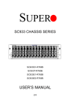
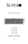
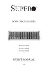
SUPER
®
BUZZER_ENB1
+
SAS933EL
BUZZER1
WWN
REV 1.12
B2
B1
B3
WWN
A2
A
R658
OVERHEATFAIL1
A1
FANFAIL1
5V_LED
C A
C A
R659
R1
PRI_BLINK
SEC_J0
SEC_BLINK
SEC_J1
PRI_J2
PRI_J1
PRI_J0
12V_LED
REMOTE_FAN_FAIL_SCOKET
C A
C
PRI_IPMI
R2
PRI_I2C
A3
FAN_ALERT_EN1
SEC_J2
SEC_I2C
SEC_IPMI
PRI_EXP
PRI_MODE4
BAR CODE
PRI_EEPROM
SEC_EEPROM
1
1
PRI_MODE5
SEC_MODE4
SEC_FLASH
PRI_FLASH
1
SEC_MODE5
FAN1
+5V
+12V
GND
GND
+5V
GND
GND
PWR3
+12V
+5V
GND
GND
PWR2
+12V
+5V
GND
GND
PWR1
+12V
FAN3
FAN2
PWR0
FAN4
BUZZER_ENB1
+
SAS933EL
BUZZER1
WWN
REV 1.12
WWN
A2
A1
A
R658
OVERHEATFAIL1
PRI_MODE4
PRI_J1
FANFAIL1
5V_LED
C A
C A
R659
R1
12V_LED
REMOTE_FAN_FAIL_SOCKET
C A
C
PRI_IPMI
R2
A3
PRI_I2C
2
20
PRI_ICE
19
1
PRI_UART
C516
1
1
PRI_SEP
BAR CODE
PRI_EEPROM
1
1
PRI_J0
PRI_EXP
FAN_ALERT_EN1
PRI_BLINK
PRI_J2
SEC_BLINK
C518
C520
R578
SEC_MODE4
PRI_FLASH
1
SEC_UART
1
SEC_SEP
SEC_MODE5
FAN1
+5V
GND
GND
+12V
PWR3
+5V
GND
GND
+12V
PWR2
+5V
GND
GND
+12V
PWR1
+5V
GND
GND
+12V
PWR0
FAN2
FAN3
SAS-933EL SERIES BACKPLANE
USER'S GUIDE
Rev. 1.0d
FAN4
SAS-933EL Backplane User's Guide
The information in this User’s Manual has been carefully reviewed and is believed to be accurate.
The vendor assumes no responsibility for any inaccuracies that may be contained in this document,
makes no commitment to update or to keep current the information in this manual, or to notify any
person or organization of the updates. Please Note: For the most up-to-date version of this
manual, please see our web site at www.supermicro.com.
Super Micro Computer, Inc. ("Supermicro") reserves the right to make changes to the product
described in this manual at any time and without notice. This product, including software and
documentation, is the property of Supermicro and/or its licensors, and is supplied only under a
license. Any use or reproduction of this product is not allowed, except as expressly permitted by
the terms of said license.
IN NO EVENT WILL SUPERMICRO BE LIABLE FOR DIRECT, INDIRECT, SPECIAL, INCIDENTAL,
SPECULATIVE OR CONSEQUENTIAL DAMAGES ARISING FROM THE USE OR INABILITY TO
USE THIS PRODUCT OR DOCUMENTATION, EVEN IF ADVISED OF THE POSSIBILITY OF
SUCH DAMAGES. IN PARTICULAR, SUPERMICRO SHALL NOT HAVE LIABILITY FOR ANY
HARDWARE, SOFTWARE, OR DATA STORED OR USED WITH THE PRODUCT, INCLUDING THE
COSTS OF REPAIRING, REPLACING, INTEGRATING, INSTALLING OR RECOVERING SUCH
HARDWARE, SOFTWARE, OR DATA.
Any disputes arising between manufacturer and customer shall be governed by the laws of Santa
Clara County in the State of California, USA. The State of California, County of Santa Clara shall
be the exclusive venue for the resolution of any such disputes. Super Micro's total liability for all
claims will not exceed the price paid for the hardware product.
California Best Management Practices Regulations for Perchlorate Materials: This Perchlorate
warning applies only to products containing CR (Manganese Dioxide) Lithium coin cells. “Perchlorate
Material-special handling may apply. See www.dtsc.ca.gov/hazardouswaste/perchlorate”
WARNING: Handling of lead solder materials used in this
product may expose you to lead, a chemical known to
the State of California to cause birth defects and other
reproductive harm.
Manual Revision 1.0d
Release Date: February 15, 2011
Unless you request and receive written permission from Super Micro Computer, Inc., you may not
copy any part of this document.
Information in this document is subject to change without notice. Other products and companies
referred to herein are trademarks or registered trademarks of their respective companies or mark
holders.
Copyright © 2011 by Super Micro Computer, Inc.
All rights reserved.
Printed in the United States of America
ii
Safety Information and Technical Specifications
Table of Contents
SAS-933EL SERIES BACKPLANE
Contacting Supermicro ........................................................................................v
Returning Merchandise for Service....................................................................vi
Chapter 1 Safety Guidelines
1-1
ESD Safety Guidelines ................................................................................... 1-1
1-2
General Safety Guidelines .............................................................................. 1-1
1-3
An Important Note to Users ............................................................................ 1-2
1-4
Introduction to the SAS-933EL Backplane...................................................... 1-2
Chapter 2 Connectors, Jumpers and LEDs
2-1
Front Connectors and Jumpers ...................................................................... 2-1
Front Connectors ............................................................................................ 2-1
2-2
Front Connector and Pin Definitions ............................................................... 2-2
2-3
Front Jumper Locations and Pin Definitions ................................................... 2-4
Explanation of Jumpers .................................................................................. 2-5
Front LED Indicators ....................................................................................... 2-6
2-4
Rear Connectors and LED Indicators ............................................................. 2-7
Chapter 3 Dual Port and Cascading Configurations
3-1
Single and Dual Port Expanders..................................................................... 3-1
Single Ports ..................................................................................................... 3-1
Dual Ports ....................................................................................................... 3-1
SAS-933EL1 Single Port Backplane ............................................................... 3-1
SAS-933EL2 Dual Port Backplane ................................................................. 3-1
3-2
Failover............................................................................................................ 3-2
Single Host Bus Adapter ................................................................................. 3-2
Single Host Bus Adapter Failover ................................................................... 3-2
3-3
Failover with RAID Cards and Multiple HBAs ................................................ 3-3
3-4
Cables and Chassis Power Card .................................................................... 3-4
Chassis Power Card ....................................................................................... 3-4
Connecting an Internal Host Bus Adapter to the Backplane ......................... 3-5
Supported Internal HBA to Backplane Cables ................................................ 3-6
Connecting an External Host Bus Adapter to the Backplane ........................ 3-8
Supported External HBA to Backplane Cable ................................................ 3-9
Connecting Multiple Backplanes in a Single Channel Environment ............. 3-10
Single HBA Conguration ............................................................................... 3-10
iii
SAS-933EL Backplane User's Guide
Single HBA Configuration Cables ..................................................................3-11
Connecting Multiple Backplanes in a Dual Channel Environment ............... 3-12
Dual HBA Conguration Cables...................................................................... 3-13
3-5
Supported Cascading Configurations ........................................................... 3-14
Server System with Single SAS HBA ........................................................... 3-15
Server System with Dual SAS HBA and Cascading Configuration .............. 3-16
Server System with Dual SAS HBA.............................................................. 3-17
Dual Cable Routing ....................................................................................... 3-18
External Cables ............................................................................................. 3-18
iv
Safety Information and Technical Specifications
Contacting Supermicro
Headquarters
Address:
Super Micro Computer, Inc.
980 Rock Ave.
San Jose, CA 95131 U.S.A.
Tel:
+1 (408) 503-8000
Fax:
+1 (408) 503-8008
Email:
[email protected] (General Information)
[email protected] (Technical Support)
Web Site:
www.supermicro.com
Europe
Address:
Super Micro Computer B.V.
Het Sterrenbeeld 28, 5215 ML
's-Hertogenbosch, The Netherlands
Tel:
+31 (0) 73-6400390
Fax:
+31 (0) 73-6416525
Email:
[email protected] (General Information)
[email protected] (Technical Support)
[email protected] (Customer Support)
Asia-Pacific
Address:
Super Micro Computer, Inc.
4F, No. 232-1, Liancheng Rd.
Chung-Ho 235, Taipei County
Taiwan, R.O.C.
Tel:
+886-(2) 8226-3990
Fax:
+886-(2) 8226-3991
Web Site:
www.supermicro.com.tw
Technical Support:
Email:
[email protected]
Tel:
886-2-8226-1900
v
SAS-933EL Backplane User's Guide
Returning Merchandise for Service
A receipt or copy of your invoice marked with the date of purchase is required before any warranty service will be rendered. You can obtain service by calling your
vendor for a Returned Merchandise Authorization (RMA) number. When returning
to the manufacturer, the RMA number should be prominently displayed on the
outside of the shipping carton, and mailed prepaid or hand-carried. Shipping and
handling charges will be applied for all orders that must be mailed when service
is complete.
For faster service, RMA authorizations may be requested online (http://www.
supermicro.com/support/rma/).
Whenever possible, repack the backplane in the original Supermicro box, using the
original packaging materials. If these are no longer available, be sure to pack the
backplane in an anti-static bag and inside the box. Make sure that there is enough
packaging material surrounding the backplane so that it does not become damaged
during shipping.
This warranty only covers normal consumer use and does not cover damages incurred in shipping or from failure due to the alteration, misuse, abuse or improper
maintenance of products.
During the warranty period, contact your distributor first for any product problems.
vi
Safety Information and Technical Specifications
Chapter 1
Safety Guidelines
To avoid personal injury and property damage, carefully follow all the safety steps
listed below when accessing your system or handling the components.
1-1
ESD Safety Guidelines
Electrostatic Discharge (ESD) can damage electronic components. To prevent damage to your system, it is important to handle it very carefully. The following measures
are generally sufficient to protect your equipment from ESD.
•
Use a grounded wrist strap designed to prevent static discharge.
•
Touch a grounded metal object before removing a component from the antistatic
bag.
•
Handle the backplane by its edges only; do not touch its components, peripheral
chips, memory modules or gold contacts.
•
When handling chips or modules, avoid touching their pins.
•
Put the card and peripherals back into their antistatic bags when not in use.
1-2
•
•
General Safety Guidelines
Always disconnect power cables before installing or removing any components
from the computer, including the backplane.
Disconnect the power cable before installing or removing any cables from the
backplane.
•
Make sure that the backplane is securely and properly installed on the motherboard to prevent damage to the system due to power shortage.
1-1
SAS-933EL Backplane User's Guide
1-3
•
An Important Note to Users
All images and layouts shown in this user's guide are based upon the latest PCB
Revision available at the time of publishing. The card you have received may or
may not look exactly the same as the graphics shown in this manual.
1-4
Introduction to the SAS-933EL Backplane
The SAS-933EL backplane has been designed to utilize the most up-to-date technology available, providing your system with reliable, high-quality performance.
This manual reflects SAS-933EL Revision 1.12 the most current release available at
the time of publication. Always refer to the Supermicro Web site at www.supermicro.
com for the latest updates, compatible parts and supported configurations.
1-2
Safety Information and Technical Specifications
Chapter 2
Connectors, Jumpers and LEDs
2-1
Front Connectors and Jumpers
1
2
BUZZER_ENB1
+
SAS933EL
BUZZER1
WWN
REV 1.12
B1
B3
WWN
A2
SEC_J0
SEC_J1
SEC_BLINK
PRI_J2
FANFAIL1
5V_LED
C A
C A
R659
R1
12V_LED
REMOTE_FAN_FAIL_SCOKET
C A
C
PRI_IPMI
R2
PRI_I2C
A3
PRI_J1
PRI_J0
PRI_EXP
SEC_EEPROM
1
1
A
R658
OVERHEATFAIL1
A1
PRI_BLINK
B2
FAN_ALERT_EN1
SEC_J2
BAR CODE
PRI_EEPROM
1
SEC_I2C
SEC_IPMI
PRI_MODE4
PRI_MODE5
SEC_MODE4
SEC_FLASH
PRI_FLASH
1
SEC_MODE5
12
6
FAN1
+5V
+12V
GND
GND
+5V
GND
+12V
GND
PWR3
+5V
GND
GND
+12V
PWR2
+5V
GND
GND
4
+12V
PWR1
PWR0
9
10
11
3
5
FAN2
7
8
3
2
5
FAN3
FAN4
6
6
6
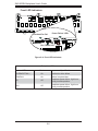
Figure 2-1: SAS-933EL2 Backplane
Front Connectors
BUZZER_ENB1
+
BUZZER_ENB1
SAS933EL
+
B2
SAS933EL
BUZZER1
WWN
REV 1.12
SEC_J2
SEC_I2C
SEC_IPMI
B1
SEC_J0
SEC_BLINK
B3
WWN
A2
PRI_J2
C516
C518
FAN_ALERT_EN1
1
1
PRI_SEP
PRI_I2C
12V_LED
REMOTE_FAN_FAIL_SOCKET
C A
C
PRI_IPMI
R2
PRI_I2C
A3
BAR CODE
2
20
PRI_ICE
19
1
BAR CODE
PRI_EEPROM
1
1
FANFAIL1
5V_LED
C A
C A
R659
R1
PRI_J1
PRI_J0
PRI_EXP
8. SAS connectors: PRI_A1
PRI_UART
SEC_MODE4
12V_LED
REMOTE_FAN_FAIL_SCOKET
C A
C
PRI_IPMI
R2
A3
A
R658
OVERHEATFAIL1
A1
PRI_EEPROM
SEC_EEPROM
PRI_MODE4
PRI_MODE5
PRI_EXP
PRI_BLINK
PRI_J2
SEC_BLINK
1
FANFAIL1
5V_LED
C A
C A
R659
R1
PRI_J1
PRI_J0
WWN
A2
PRI_MODE4
1
A
R658
OVERHEATFAIL1
A1
7. SAS connectors: PRI_A3
PRI_BLINK
SEC_J1
WWN
REV 1.12
FAN_ALERT_EN1
1. Primary and secondary I2C connectors (optional)
BUZZER1
SEC_FLASH
PRI_FLASH
1
R578
SEC_MODE4
C520
2. Primary and secondary flash chip
9. SAS connectors: PRI_A2
SEC_MODE5
1
SEC_UART
1
SEC_SEP
SEC_MODE5
3. Primary and secondary expander chip
FAN1
10. SAS connectors: SEC_B3 (not available in EL1 single port backplane)
4. Power connectors: PWR0, PWR1,
PWR2, and PWR3
+5V
+12V
GND
GND
+5V
GND
GND
+12V
+5V
GND
GND
+12V
+5V
GND
GND
PRI_FLASH
+12V
FAN1
5. EPP connectors: J15 and J16
11. SAS connectors: SEC_B1 (not available in EL1 single port backplane)
6. Fan connectors: Fan1, Fan2, Fan3,
and Fan4
12. SAS connectors: SEC_B2 (not available in EL1 single port backplane)
+5V PWR3 GND
+5V PWR2 GND
+12V
GND
GND
PWR3
+5VPWR1 GND
+12V
GND
PWR2
+5VPWR0 GND
+12V
GND
PWR1
FAN3
FAN2
+12V
FAN4
FAN3
FAN2
PWR0
FAN4
1
BUZZER_ENB1
+
SAS933EL
BUZZER1
WWN
REV 1.12
WWN
A2
A1
A
R658
OVERHEATFAIL1
FANFAIL1
5V_LED
C A
C A
R659
R1
FAN_ALERT_EN1
PRI_EXP
PRI_I2C
2
20
PRI_ICE
19
1
PRI_UART
C516
1
1
PRI_SEP
BAR CODE
PRI_EEPROM
1
1
PRI_J1
PRI_J0
12V_LED
REMOTE_FAN_FAIL_SOCKET
C A
C
PRI_IPMI
R2
A3
PRI_BLINK
PRI_J2
SEC_BLINK
PRI_MODE4
C518
C520
R578
SEC_MODE4
PRI_FLASH
1
SEC_UART
1
SEC_SEP
9
SEC_MODE5
3
6
FAN1
+5V
GND
GND
+12V
PWR3
+5V
GND
GND
+12V
PWR2
+5V
GND
GND
+12V
PWR1
+5V
GND
GND
+12V
PWR0
4
8
3
FAN3
FAN2
6
6
Figure 2-2: SAS-933EL1 Backplane
2-1
7
2
5
FAN4
6
SAS-933EL Backplane User's Guide
2-2
Front Connector and Pin Definitions
1. Primary and Secondary I2C Connectors
I2C Connector
Pin Definitions
The I2C connectors are used to monitor the
power supply and to control the fans. See
Pin#
Definition
the table on the right for pin definitions. There
are two connectors, one primary and one
1
Data
2
Ground
3
Clock
4
No Connection
secondary.
These connectors are optional and should only
be used by qualified technicians.
2. Primary and Secondary Flash Chips
The primary and secondary flash chips enhance the backplane memory.
3. Primary and Secondary Expander Chips
This primary and secondary expander chips
allow the backplane to support dual ports,
cascading, and failover.
4. Backplane Main Power Connectors
The 4-pin connectors, designated PWR0,
PWR1, PWR2, and PWR3, provide power to
the backplane. See the table on the right for
pin definitions.
Backplane
Main Power
4-Pin Connector
(PWR0, PWR1, PWR2,
and PWR3)
Pin#
1
2 and 3
4
5. EPP Ports
The EPP ports are used for manufacturer
diagnostic purposes only.
2-2
Definition
+12V
Ground
+5V
Safety Information and Technical Specifications
6. Fan Connectors
The 3-pin connectors, designated Fan1, Fan2,
Fan3, and Fan4, provide power to the system
Fan Connectors
(Fan1, Fan2, Fan3,
and Fan4)
Pin#
Definition
fans. See the table on the right for pin defini-
1
Ground
tions.
2
+12V
3
Tachometer
7 - 12. SAS Ports
Note that the primary and secondary sets of
SAS ports are in different order. From right to
left the ports are Primary A3, A1, and A2 and
Secondary B3, B1, and B2.
2-3
2-3
Front Jumper Locations and Pin Definitions
SAS933EL
WWN
B3
REV
EV 1.12
B1
WWN
B1
A2
B3
A2
PRI_BLINK
SEC_J2
B2
SEC_J0
SEC_J1
SEC_BLINK
PRI_J2
SEC_J0
SEC_J1
PRI_J2
PRI_J0
PRI_EXP
PRI_BLINK
SEC_BLINK
PRI_EEPROM
PRI_EEPR
SEC_EEPROM
SEC_E
BUZZER_ENB1
+
SAS933EL
BUZZER1
WWN
REV 1.12
B1
B3
WWN
A2
A
R658
OVERHEATFAIL1
A1
FANFAIL1
5V_LED
C A
C A
R659
R1
SEC_J0
SEC_J1
SEC_BLINK
PRI_J2
PRI_J1
PRI_J0
12V_LED
REMOTE_FAN_FAIL_SCOKET
C A
C
PRI_IPMI
R2
PRI_I2C
A3
PRI_BLINK
B2
FAN_ALERT_EN1
SEC_J2
SEC_I2C
SEC_IPMI
SEC_FLASH
PRI_EXP
PRI_MODE4
BAR CODE
PRI_EEPROM
SEC_EEPROM
1
1
PRI_MODE5
SEC_MODE4
SEC_FLASH
PRI_FLASH
1
SEC_MODE5
FAN1
+5V
+12V
GND
GND
+5V
GND
GND
PWR3
+12V
+5V
GND
GND
PWR2
+12V
+5V
GND
GND
PWR1
+12V
FAN3
FAN2
PWR0
FAN4
Buzzer Enable
Remote_Fan_Fail_Socket
BUZZER_ENB1
+
BUZZER1
A1
A
R658
OVERHEATFAIL1
12V_LED
REMOTE_FAN_FAIL_SCOKET
C A
C
PRI_IPMI
R2
PRI_J1
BUZZER_ENB1
+
PRI_MODE4
BUZZER1
SAS933EL
WWN
REV 1.12
SEC_J2
WWN
A2
A1
A
R658
OVERHEATFAIL1
FANFAIL1
5V_LED
C A
C A
R659
R1
12V_LED
REMOTE_FAN_FAIL_SOCKET
C A
C
PRI_IPMI
R2
+12V
PRI_MODE4
PRI_
Mode5
1
1
PRI_SEP
SEC_MODE4
FAN2
PRI_Mode4
1
C516
1
1
20
19
1
BAR CODE
1
FAN3
PRI_FLASH
PRI_MODE5
SEC_UART
FAN2
1
SEC_SEP
SEC_MODE5
Fan Alert Enable1
SEC_
Mode4
SEC_MODE4
SEC_FLASH
1
FAN1
+5V
2
PRI_ICE
C518
R578
PWR0
BAR CODE
PRI_EEPROM
1
PRI_UART
PRI_J1
PRI_J0
PRI_EXP
B2
SEC_EEPROM
GND
FAN_ALERT_EN1
GND
GND
GND
+12V
PWR3
+5V
GND
GND
+12V
+5V
GND
GND
PWR2
+12V
+5V
GND
PWR1
SEC_
Mode5
GND
PRI_FLASH
+12V
SEC_MODE5
FAN3
FAN2
PWR0
FAN4
Figure 2-3: Front Jumpers
Socket Settings
Socket
Socket Setting
REMOTE_FAN_FAIL_
SOCKET
Notes
Front panel fan fail indicator
(Optional)
Connected
FAN1
+5V
GND
GND
+12V
PWR3
FAN3
+5V
GND
GND
2-4
+12V
PWR2
+5V
GND
GND
+12V
+5V
REV 1.12
PRI_I2C
A3
PRI_BLINK
PRI_J2
SEC_BLINK
+5V
SAS933EL
PRI_I2C
A3
FAN_ALERT_EN1
SEC_I2C
SEC_IPMI
PRI_J0
FANFAIL1
5V_LED
V_LED
C A
C A
R659
R1
PRI_EXP
C520
WR1
SAS-933EL Backplane User's Guide
GND
GND
PWR1
+12V
PWR0
FAN4
A1
Safety Information and Technical Specifications
General Jumper Settings
Jumper
Jumper Settings
Note
PRI_MODE4
1-2
Factory setting
Do not change
PRI_MODE5
2-3
Factory setting
Do not change
PRI_BLINK
Open
Factory setting
Do not change
SEC_MODE4
1-2
Factory setting
Do not change
SEC_MODE5
2-3
Factory setting
Do not change
SEC_BLINK
Open
Factory setting
Do not change
BUZZER_ENB
Open: Disable
Closed: Enable
Buzzer enable*
FAN_ALERT_ENI
Open: Disable
Closed: Enable
Fan alert enable
Explanation of Jumpers
To modify the operation of the backplane,
jumpers can be used to choose between
optional settings. Jumpers create shorts
between two pins to change the function
of the connector. Pin 1 is identified with
a square solder pad on the printed circuit
board. Note: On two pin jumpers, "Closed"
means the jumper is on and "Open" means
the jumper is off the pins.
3
2
1
3
2
1
Connector
Pins
Jumper
Setting
*The buzzer sound indicates that a condition requiring immediate attention has
occurred.
The buzzer alarm is triggered by the following conditions:
1. Hard drive failure
2. Fan failure
3. System temperature over 45º Celsius.
2-5
SAS-933EL Backplane User's Guide
Front LED Indicators
BUZZER_ENB1
+
SAS933EL
BUZZER1
WWN
REV 1.12
B2
B1
B3
WWN
A2
A
R658
OVERHEATFAIL1
A1
FANFAIL1
5V_LED
C A
C A
R659
R1
PRI_BLINK
SEC_J0
SEC_J1
SEC_BLINK
PRI_J2
PRI_J1
PRI_J0
12V_LED
REMOTE_FAN_FAIL_SCOKET
C A
C
PRI_IPMI
R2
PRI_I2C
A3
FAN_ALERT_EN1
SEC_J2
SEC_I2C
SEC_IPMI
PRI_EXP
PRI_MODE4
BAR CODE
PRI_EEPROM
SEC_EEPROM
1
1
PRI_MODE5
SEC_MODE4
SEC_FLASH
PRI_FLASH
1
SEC_MODE5
FAN1
+5V
+12V
GND
GND
+5V
GND
GND
+12V
PWR3
+5V
GND
GND
PWR2
+12V
+5V
GND
GND
PWR1
+12V
FAN3
FAN2
PWR0
Overheat/Fan Fail
A1
Power Failure LEDs
FANFAIL1
5V_LED
C A
C A
R659
R1
A
R658
OVERHEATFAIL1
Fan Failure LED
12V_LED
REMOTE_FAN_FAIL_SCOKET
REMOTE_FAN_FA
C A
C
PRI_IPMI
PR
R2
A3
+
SAS933EL
BUZZER1
WWN
REV 1.12
WWN
A2
PRI_BLINK
PRI_J2
SEC_BLINK
PRI_UART
C516
PRI_EEPROM
1
1
1
1
PRI_SEP
C518
C520
R578
SEC_MODE4
1
SEC_UART
1
SEC_SEP
SEC_MODE5
Figure 2-4: Front LED Indicators
FAN1
+5V
GND
GND
+12V
+5V
GND
PWR3
GND
+12V
PWR2
+5V
GND
GND
+12V
PWR1
+5V
GND
GND
A
R658
OVERHEATFAIL1
A1
PRI_J1
PRI_J0
PRI_EXP
+12V
FAN3
FAN2
PWR0
FANFAIL1
5V_LED
C A
C A
R659
R1
12V_LED
REMOTE_FAN_FAIL_SOCKET
C A
C
PRI_IPMI
R2
A3
FAN_ALERT_EN1
PRI_MODE4
PRI_J1
FAN_ALERT_EN1
FAN_AL
BUZZER_ENB1
PRI_J0
FAN4
PRI_I2C
2
20
PRI_ICE
19
1
BAR CODE
PRI_FLASH
BAR CODE
FAN4
Backplane LEDs
LED
State
Specification
OVERHEATFAIL1
On
Overheat or drive failure
FANFAIL1
On
Failure in system fans
5V
Off
Backplane power failure. Light is on
during normal operation.
Off
Backplane power failure. Light is on
during normal operation.
PRI_FLASH
12V
2-6
PRI_I2C
Safety Information and Technical Specifications
2-4
Rear Connectors and LED Indicators
SAS #0
#0
FAIL1
PRI_SRAM2
CA
C
ACT1
J1
CA
C ACT2
#2
SAS #2
FAIL3
A
CA
C
ACT3
J3
#3
FAIL4
SAS #3
A
CA
C
ACT4
J4
#4
FAIL#4
ACT#4
SAS #1
A
J2
FAIL#3
ACT#3
PRI_SRAM1
#1
FAIL2
FAIL#2
ACT#2
J0
A
FAIL#1
ACT#1
FAIL5
SAS #4
A
CA
C
ACT5
SAS #6
FAIL6
SAS #5
#6
J5
#5
FAIL#5
ACT#5
A
CA
C
ACT6
FAIL#6
ACT#6
J6
FAIL7
A
CA
C
ACT7
FAIL#7
ACT#7
J7
#7
FAIL8
SAS #7
C75
A
CA
C
ACT8
FAIL#8
ACT#8
J8
#8
FAIL9
SAS #8
C77
A
CA
C ACT9
FAIL#9
ACT#9
J9
#9
FAIL10
SAS #9
A
CA
C
ACT10
FAIL#10
ACT#10
J10
#10
FAIL11
SAS #10
A
CA
C ACT11
J11
SAS #11
SEC_SRAM1
A
CA
C
ACT12
J12
SAS #12
#13
SAS #13
#14
SAS #14
A
#12
FAIL13
FAIL#12
ACT#12
SEC_SRAM2
FAIL12
#11
FAIL#11
ACT#11
CA
C ACT13
J13
FAIL14
FAIL#13
ACT#13
A
CA
C
ACT14
FAIL#14
ACT#14
J14
FAIL15
A
CA
C
ACT15
FAIL#15
ACT#15
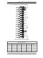
Figure 2-5: Rear Connectors and LEDs
Rear SAS Connectors
Connector
SAS Drive
Connector
SAS Drive
Connector
SAS #0
SAS HDD #0
SAS #5
SAS HDD #5
SAS #10
SAS HDD #10
SAS #1
SAS HDD #1
SAS #6
SAS HDD #6
SAS #11
SAS HDD #11
SAS #2
SAS HDD #2
SAS #7
SAS HDD #7
SAS #12
SAS HDD #12
SAS #3
SAS HDD #3
SAS #8
SAS HDD #8
SAS #13
SAS HDD #13
SAS #4
SAS HDD #4
SAS #9
SAS HDD #9
SAS #14
SAS HDD #14
2-7
SAS Drive
SAS-933EL Backplane User's Guide
Rear LED Indicators
Rear LED
Hard Drive Activity
Failure LED
SAS #0
ACT #1
FAIL #1
SAS #1
ACT #2
FAIL #2
SAS #2
ACT #3
FAIL #3
SAS #3
ACT #4
FAIL #4
SAS #4
ACT #5
FAIL #5
SAS #5
ACT #6
FAIL #6
SAS #6
ACT #7
FAIL #7
SAS #7
ACT #8
FAIL #8
SAS #8
ACT #9
FAIL #9
SAS #9
ACT #10
FAIL #10
SAS #10
ACT #11
FAIL #11
SAS #11
ACT #12
FAIL #12
SAS #12
ACT #13
FAIL #13
SAS #13
ACT #14
FAIL #14
SAS #14
ACT #15
FAIL #15
2-8
Safety Information and Technical Specifications
Chapter 3
Dual Port and Cascading Configurations
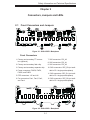
3-1
Single and Dual Port Expanders
Single Ports
BUZZER_ENB1
+
SAS933EL
BUZZER1
WWN
REV 1.12
B1
B3
WWN
A2
A
R658
OVERHEATFAIL1
A1
FANFAIL1
5V_LED
C A
C A
R659
R1
12V_LED
REMOTE_FAN_FAIL_SCOKET
C A
C
PRI_IPMI
R2
SEC_J0
SEC_J1
SEC_BLINK
PRI_J2
PRI_J1
PRI_J0
PRI_I2C
A3
PRI_BLINK
B2
FAN_ALERT_EN1
SEC_J2
SEC_I2C
SEC_IPMI
PRI_EXP
PRI_MODE4
PRI_MODE5
BAR CODE
PRI_EEPROM
SEC_EEPROM
1
1
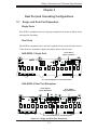
SAS-933EL1 backplanes have a single port expander that access all fifteen drives
SEC_MODE4
SEC_FLASH
PRI_FLASH
1
and supports cascading.
SEC_MODE5
Dual Ports
FAN1
+5V
+12V
GND
GND
+5V
GND
GND
PWR3
+12V
+5V
GND
GND
PWR2
+12V
+5V
GND
GND
PWR1
+12V
FAN3
FAN2
PWR0
FAN4
SAS-933EL2 backplanes have dual port expanders that access all fifteen drives.
These dual port expanders support cascading, failover, and recovery.
From HBA or
higher backplane
SAS-933EL1 Single Port
BUZZER_ENB1
+
SAS933EL
BUZZER1
WWN
REV 1.12
WWN
A2
A
R658
OVERHEATFAIL1
A1
FANFAIL1
5V_LED
C A
C A
R659
R1
12V_LED
REMOTE_FAN_FAIL_SOCKET
C A
C
PRI_IPMI
R2
PRI_EXP
C516
1
1
1
PRI_SEP
C518
20
19
1
A3
BAR CODE
C520
R578
SEC_MODE4
2
PRI_ICE
A1
PRI_EEPROM
A2
PRI_UART
1
FAN_ALERT_EN1
PRI_MODE4
PRI_J1
PRI_J0
PRI_I2C
A3
PRI_BLINK
PRI_J2
SEC_BLINK
PRI_FLASH
1
SEC_UART
1
SEC_SEP
SEC_MODE5
FAN1
+5V
GND
GND
+12V
+5V
GND
GND
PWR3
+12V
+5V
GND
GND
PWR2
+12V
+5V
GND
GND
+12V
PWR1
FAN3
FAN2
PWR0
FAN4
To Lower Backplane in Cascaded System
SAS-933EL2 Dual Port Backplane
From HBA or
Higher Backplane
From HBA or
Higher Backplane
A2
B3
BUZZER_ENB1
+
SAS933EL
BUZZER1
PRI_MODE4
B2
SEC_MODE4
SEC_J1
WWN
A2
A
R658
OVERHEATFAIL1
A1
PRI_J2
FANFAIL1
5V_LED
C A
C A
R659
R1
PRI_J1
PRI_J0
PRI_EXP
B1
12V_LED
REMOTE_FAN_FAIL_SCOKET
C A
C
PRI_IPMI
R2
A3
PRI_I2C
A3
A1
PRI_EEPROM
PRI_MODE5
B3
PRI_BLINK
SEC_J0
SEC_BLINK
SEC_EEPROM
B2
1
1
B1
FAN_ALERT_EN1
SEC_J2
SEC_I2C
SEC_IPMI
WWN
REV 1.12
BAR CODE
SEC_FLASH
PRI_FLASH
1
SEC_MODE5
FAN1
+5V
GND
GND
+12V
+5V
PWR3
GND
GND
+12V
PWR2
+5V
GND
GND
+12V
PWR1
+5V
GND
GND
+12V
FAN3
FAN2
PWR0
FAN4
To Lower Backplane in cascaded system
Figure 3-1: Single and Dual Port Backplanes
3-1
BUZZER_ENB1
+
BUZZER1
SAS933EL
WWN
REV 1.12
A2
WWN
A1
A
R658
OVERHEATFAIL1
PRI_J2
PRI_J0
PRI_EXP
PRI_J1
FANFAIL1
5V_LED
C A
C A
R659
R1
12V_LED
REMOTE_FAN_FAIL_SOCKET
C A
C
PRI_IPMI
R2
A3
FAN_AL
PRI_BLINK
SEC_BLINK
2
PRI_I2C
SAS-933EL Backplane User's Guide
3-2
Failover
The SAS-933EL2 backplane has two expanders which allow effective failover and
recovery.
Single Host Bus Adapter
SAS HBA
In a single host bus configuration, the
backplane connects to one Host Bus
Adapter (HBA).
B1
SEC_J2
B2
SEC_J0
B3
SEC_J1
A2
PRI_J1
Port A
Expander 1
Port B
Expander 2
Single Host Bus Adapter
Failover
A3
A1
PRI_J2
SAS HBA
If the expander or data path in Port
A fails, the system will automatically
switch over to Port B.
B1
SEC_J2
B2
SEC_J0
Port B
Expander 2
Figure 3-2: Failover with a Single HBA
3-2
B3
SEC_J1
A2
PRI_J2
A3
A1
PRI_J1
Port A
Expander 1
Safety Information and Technical Specifications
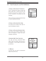
3-3
Failover with RAID Cards and Multiple HBAs
The SAS-933EL backplane may be configured for failover with multiple HBAs using
either RAID controllers or HBAs to acheive failover protection.
RAID Controllers: If RAID controllers are used, then the failover is accomplished
through port failover on the same RAID card.
HBAs: If multiple HBAs are used to achieve failover protection and load balancing,
Linux MPIO software must be installed and correctly configured to perform the
load balancing and failover tasks.
Dual Host Bus Adapter
SAS HBA
In a dual host bus configuration, the
backplane connects to two Host Bus
Adapters.
SAS HBA
B1
SEC_J2
B2
SEC_J0
B3
SEC_J1
A2
PRI_J1
Port B
Expander 2
Dual Host Bus Adapter
Failover
A3
A1
PRI_J2
Port A
Expander 1
SAS HBA
If the expander or data path in Port A
fails, the system will automatically fail
over to Port B. This maintains a full
connection to all drives.
SAS HBA
B1
SEC_J2
B2
SEC_J0
Port B
Expander 2
B3
SEC_J1
A2
PRI_J2
A3
A1
PRI_J1
Port A
Expander 1
Figure 3-3: Failover with Dual HBAs
!
IMPORTANT: For RAID controllers, redundancy is achieved
through port failover. For multiple HBAs MPIO software is
required to achieve failover protection.
3-3
SAS-933EL Backplane User's Guide
3-4
Cables and Chassis Power Card
Chassis Power Card
In a cascaded configuration, the first chassis includes a motherboard and, at least
one, HBA. Other servers in this enclosed system, include a power card. This section
describes the supported power card for the SAS-933 backlplane system.
A
A
A
JBPWR2 REV 1.00
Figure 3-4: Power Card
Power Card
Part Number
Part Type
CSE-PTJBOD-CB1
Power Card
3-4
Where Used
Allows the chassis to be in a
JBOD (Just a Bunch of Drives)
system.
Safety Information and Technical Specifications
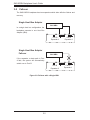
Connecting an Internal Host Bus Adapter to the
Backplane
The following section lists the most common cables used to connect the HBA to
the backplane.
B1
SEC_J2
B2
B3
SEC_J0
A3
A1
A2
SEC_J1
PRI_J1
PRI_J2
HBA
Single Internal Host Bus Adapter
B1
SEC_J2
B2
SEC_J0
B3
SEC_J1
A2
PRI_J2
A3
A1
PRI_J1
HBA
HBA
Dual Internal Host Bus Adapter
Figure 3-5: Single and Dual HBAs
IMPORTANT: See Section 3-3 of this manual, Failover with RAID Cards and Multiple
HBAs for important information on supported configurations.
3-5
SAS-933EL Backplane User's Guide
Supported Internal HBA to Backplane Cables
Use the following listed cables to create connections between the internal HBA and
backplane. The cables required depend on the HBA connector.
Figure 3-6: iPass to 4-lane Cable (CBL-0117)
Cable Name: iPass to 4-Lane
Part #: CBL-0117
Length: 46 cm (18 inches)
Description: This cable has one SFF-8484 (32-pin) connector on one end and iPass
(SFF-8087/Mini-SAS) connector (36-pin) at the other. This cable connects from the
HBA to the SAS-933EL backplane.
3-6
Safety Information and Technical Specifications
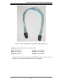
Figure 3-7: iPass (Mini-SAS) to iPass (Mini-SAS) (CBL-0110L-2)
Cable Name: iPass (Mini-SAS) to iPass (Mini-SAS)
Part #: CBL-0108L-02
Length: 39 cm (15 inches)
Part #: CBL-0109L-02
Length: 22 cm (9 inches)
Part #: CBL-0110L-02
Length: 18 cm (7 inches)
Description: This cable has an iPass (SFF-8087/Mini-SAS) connector (36-pin) at
each end. It connects from the HBA to the 933 EL backplane.
3-7
SAS-933EL Backplane User's Guide
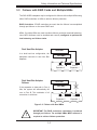
Connecting an External Host Bus Adapter to the
Backplane
This backplane supports external Host Bus Adapters. In this configuration, the HBA
and the backplane are in different physical chassis. This allows a JBOD (Just a
Bunch Of Drives) configuration from an existing system.
B1
SEC_J2
HBA
B2
B3
SEC_J0
A3
A1
A2
SEC_J1
PRI_J1
PRI_J2
Power Card
Single External Host Bus Adapter
CBL-0200L
External HBA Cable
B1
SEC_J2
B2
SEC_J0
B3
SEC_J1
A2
PRI_J2
A3
A1
PRI_J1
HBA
HBA
Power Card
Dual External Host Bus Adapter
CBL-0200L
External HBA Cables
Figure 3-8: Connecting an External HBA
IMPORTANT: See Section 3-3 of this manual, Failover with RAID Cards and Multiple
HBAs for important information on supported configurations.
3-8
Safety Information and Technical Specifications
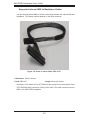
Supported External HBA to Backplane Cable
Use the following cable if your external HBA has an InfiniBand connector.
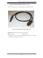
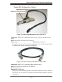
Figure 3-9: SAS InfiniBand to Mini-SAS (CBL-0200L)
Cable Name: SAS InfiniBand to Mini-SAS X4 1M cable, PBF
Part #: CBL-0200L
Length: 1 meter
Description: This cable has an InfiniBand connector (SFF-8470) on one end and
an SFF-8088-1X (26-pins) at the other end.
3-9
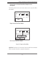
SAS-933EL Backplane User's Guide
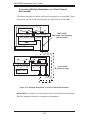
Connecting Multiple Backplanes in a Single Channel
Environment
This section describes the cables used when cascading from a single HBA. These
connections use CBL-0167L internal cables and CBL-0166L external cables.
Single HBA Conguration
B1
SEC_J2
B2
SEC_J0
B3
SEC_J1
A2
A3
A1
PRI_J1
PRI_J2
Port A Expander 1
Port B Expander 2
CBL-0167L
with Single Port Assembly
(Internal cable)
HBA
B1
SEC_J2
B2
SEC_J0
Port B Expander 2
B3
SEC_J1
A2
PRI_J2
A3
A1
PRI_J1
Port A Expander 1
CBL-0166L
(External cable)
Power Card
Figure 3-10: Multiple Backplanes in a Single Channel Environment
3-10
Safety Information and Technical Specifications
Single HBA Configuration Cables
Single Port Cable Assembly
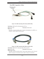
Figure 3-11: SAS Internal Backplane Cable (CBL-0167L)
Cable Name: SAS EL2/EL1 Backplane Cable (Internal) w/ 2-port Cascading Cable,
68 cm
Part #: CBL-0167L (SFF-8087 to SFF-8088 x1)
Ports: Single
Placement: Internal cable
Description: Internal cable. Connects the backplane to the Host Bus Adapter (HBA)
or external port. Used in single port environments.
Figure 3-12: SAS Cascading Cable External (CBL-0166L)
Cable Name: SAS EL2/EL1 Cascading Cable (External), 68 cm
Part #: CBL-0166L (SFF-8088 1x to SFF-8088 x1)
Ports: Single or Dual
Placement: External cable
Description: External cascading cable. Connects ports between servers. With most
connectors, use one cable for single port connections and two cables for dual port
connections.
3-11
SAS-933EL Backplane User's Guide
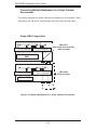
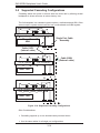
Connecting Multiple Backplanes in a Dual Channel
Environment
This section describes the cables used when cascading from a single HBA. These
connections use CBL-0168L internal cables and CBL-0166L external cables.
B1
SEC_J2
B2
SEC_J0
B3
SEC_J1
Port B Expander 2
A3
A1
A2
PRI_J1
PRI_J2
Port A Expander 1
Cable 0168L
with Single Port Assembly
(Internal cable)
HBA
HBA
B1
SEC_J2
B2
SEC_J0
Port B Expander 2
B3
SEC_J1
A2
PRI_J2
A3
A1
PRI_J1
Port A Expander 1
Cable 0166L
(External cable)
Power Card
Figure 3-13: Multiple Backplanes in a Dual Channel Environment
IMPORTANT: See Section 3-3 of this manual, Failover with RAID Cards and Multiple
HBAs for important information on supported configurations.
3-12
Safety Information and Technical Specifications
Dual HBA Conguration Cables
Dual Port Cable
Assembly
Figure 3-14: SAS Cascading Cable Internal (CBL-0168L)
Cable Name: SAS Dual Port Cable Assembly, 68/76 cm
Part #: CBL-0168L
Ports: Dual
Placement: Internal cable
Description: Internal cascading cable. Connects the backplane to the HBA or external port. Used in dual port environments.
Figure 3-15: SAS Cascading Cable External (CBL-0166L)
Cable Name: SAS EL2/EL1 Cascading Cable (External), 68 cm
Part #: CBL-0166L
Placement: External cable
Ports: Single or Dual
Description: External cascading cable. Connects ports between servers. Use one
cable for single port connections and two cables for dual port connections.
3-13
SAS-933EL Backplane User's Guide
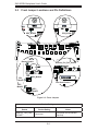
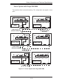
3-5
Supported Cascading Configurations
Cascading allows the system to access data at a faster rate by allowing several
backplanes to share resources to reduce latency time.
The first backplane in a cascaded system requires a motherboard and HBA. Other
servers require a power control card, but not a motherboard and HBA together.
B1
SEC_J2
B2
B3
SEC_J0
A3
A1
A2
SEC_J1
PRI_J1
PRI_J2
Port B Expander 2
Port A Expander 1
Single Port Cable
Assembly
HBA
Cable 0167L
(Internal cable)
B1
SEC_J2
B2
B3
SEC_J0
A3
A1
A2
SEC_J1
PRI_J1
PRI_J2
Port B Expander 2
Port A Expander 1
Cable 0166L
(External cable)
Power Card
B1
SEC_J2
B2
SEC_J0
B3
SEC_J1
A2
PRI_J2
Port B Expander 2
A3
A1
PRI_J1
Port A Expander 1
Power Card
Figure 3-16: Supported Cascading Configurations
Other Considerations:
•
Cascading supports up to one hundred twenty-two hard drives
•
Use the same cables for all single port configurations
3-14
Safety Information and Technical Specifications
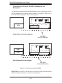
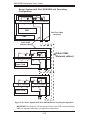
Server System with Single SAS HBA
The exanders allow horizontal branching. This configuration also applies to dual
ports.
B1
B3
B1
A3
A1
A2
SEC_J2
SEC_J2
B2
SEC_J0
SEC_J1
B2
PRI_J1
PRI_J2
B3
SEC_J0
PRI_J1
PRI_J2
Port A Expander 1
Port A Expander 1
Power Card
HBA
Cable 0167L
(Internal cable)
Single Port Cable
Assembly
B1
SEC_J2
B1
SEC_J2
A3
A1
A2
SEC_J1
B2
SEC_J0
B3
SEC_J1
A2
B2
B3
SEC_J0
A3
A1
A2
SEC_J1
PRI_J1
PRI_J2
A3
A1
PRI_J1
PRI_J2
Port A Expander 1
Port A Expander 1
Power Card
Power Card
Cable 0166L
(External cable)
B1
SEC_J2
B1
SEC_J2
B2
SEC_J0
B3
SEC_J1
A2
PRI_J2
B2
SEC_J0
B3
SEC_J1
A2
PRI_J2
A3
A1
PRI_J1
A3
A1
PRI_J1
Port A Expander 1
Port A Expander 1
Power Card
Power Card
Figure 3-17: Server System with Single SAS HBA
3-15
SAS-933EL Backplane User's Guide
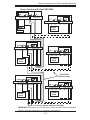
Server System with Dual SAS HBA and Cascading
Configuration
B1
SEC_J2
B2
B3
SEC_J0
SEC_J1
A3
A1
A2
PRI_J1
PRI_J2
Port A Expander 1
Port B Expander 2
HBA
Dual Port Cable
Assembly
HBA
Cable 0168L
(internal cable)
B1
SEC_J2
B2
B3
SEC_J0
A3
A1
A2
SEC_J1
PRI_J1
PRI_J2
Port B Expander 2
Port A Expander 1
Cable 0166L
(External cables)
Power Card
B1
SEC_J2
B2
SEC_J0
Port B Expander 2
B3
SEC_J1
A2
PRI_J2
A3
A1
PRI_J1
Port A Expander 1
Power Card
Figure 3-18: Server System with Dual SAS HBA and Cascading Configuration
IMPORTANT: See Section 3-3 of this manual, Failover with RAID Cards and Multiple
HBAs for important information on supported configurations.
3-16
Safety Information and Technical Specifications
Server System with Dual SAS HBA
B1
SEC_J2
B2
SEC_J0
B3
SEC_J1
A3
A1
A2
PRI_J1
PRI_J2
Port B Ex. 2
Port A Ex. 1
B1
SEC_J2
B2
B3
SEC_J0
PRI_J1
PRI_J2
Port A Ex. 1
Port B Ex. 2
HBA
A3
A1
A2
SEC_J1
Power
Card
HBA
B1
SEC_J2
B2
SEC_J0
B3
SEC_J1
A2
A3
A1
PRI_J1
PRI_J2
Port B Ex. 2
Port A Ex. 1
B1
SEC_J2
B2
SEC_J0
B3
SEC_J1
A2
A3
A1
PRI_J1
PRI_J2
Port A Ex. 1
Port B Ex. 2
Power
Card
Power
Card
Cable 0166L
(external cable)
B1
SEC_J2
B2
SEC_J0
Port B Ex. 2
B3
SEC_J1
A2
PRI_J2
A3
A1
PRI_J1
Port A Ex. 1
B1
SEC_J2
B2
SEC_J0
Port B Ex. 2
B3
SEC_J1
A2
PRI_J2
A3
A1
PRI_J1
Port A Ex. 1
Power
Card
Power
Card
Figure 3-19: Server System with Dual SAS HBA
IMPORTANT: See Section 3-3 of this manual, Failover with RAID Cards and Multiple
HBAs for important information on supported configurations.
3-17
SAS-933EL Backplane User's Guide
Dual Cable Routing
External Cables
In the previous diagrams external
cables are represented with two different line patterns. These cables are both
CBL-0166L external cables. Different
lines help the user determine cable
routing.
3-18
CBL-0166L
(external cable)
Safety Information and Technical Specifications
Notes
3-19
SAS-933EL Backplane User's Guide
Disclaimer (cont.)
The products sold by Supermicro are not intended for and will not be used in life support systems, medical equipment, nuclear facilities or systems, aircraft, aircraft devices,
aircraft/emergency communication devices or other critical systems whose failure to perform be reasonably expected to result in significant injury or loss of life or catastrophic
property damage. Accordingly, Supermicro disclaims any and all liability, and should
buyer use or sell such products for use in such ultra-hazardous applications, it does so
entirely at its own risk. Furthermore, buyer agrees to fully indemnify, defend and hold
Supermicro harmless for and against any and all claims, demands, actions, litigation,
and proceedings of any kind arising out of or related to such ultra-hazardous use or
sale.
3-20


![KeyView [4823353_1.wpd]](http://vs1.manualzilla.com/store/data/005667242_1-589c8deb81b55e7c0d34a0d078158765-150x150.png)