1
5971-2668 Small.fm Page 1 Wednesday, September 22, 2004 2:20 PM
Errata
This manual may contain references to HP or Hewlett-Packard. Please note that Hewlett-Packard's former test
and measurement, semiconductor products and chemical analysis businesses are now part of Agilent
Technologies. To reduce potential confusion, the only change to product numbers and names has been in the
company name prefix: where a product number/name was HP XXXX the current name/number is now Agilent
XXXX. For example, model number HP8648 is now model number Agilent 8648.
Ce manuel peut contenir des références à <<HP>> ou <<Hewlett-Packard.>> Veuillez noter que les produits de
test et mesure, de semi-conducteur et d'analyse chimique qui avaient fait partie de la société Hewlett-Packard
sont maintenent une partie de la société Agilent Technologies. Pour reduire la confusion potentielle, le seul
changement aux noms de reference a été dans le préfixe de nom de société : là où un nom de référence était HP
XXXX, le nouveau nom de référence est maintenant Agilent XXXX. Par example, le HP 8648 s'appelle
maintenent Agilent 8648.
Diese Gebrauchsanweiseung kann Bezug nehmen auf die Namen HP oder Hewlett-Packard. Bitte beachten Sie,
dass ehemalige Betriebsbereiche von Hewlett-Packard wie HP-Halbleiterprodukte, HP-chemische Analysen
oder HP-Test- und Messwesen nun zu der Firma Agilent Technology gehören. Um Verwirrung zu vermeiden
wurde lediglich bei Produktname und - Nummer der vo laufende Firmenname geändert: Produkte mit dem
Namen/Nummer HP XXXX lauten nun mehr Agilent XXXX. Z.B, das Modell HP 8648 heißt nun Agilent 8648.
Questo manuale potrebbe contenere riferimenti ad HP o Hewlett-Packard. Si noti che le attività precedentemente
gestite da Hewlett-Packard nel campo di Test & Misura, Semiconduttori, ed Analisi Chimica sono ora diventate
parte di Agilent Technologies. Al fine di ridurre il rischio di confusione, l'unica modifica effettuata sui numeri di
prodotto e sui nomi ha riguardato il prefisso con il nome dell'azienda : dove precedentemente compariva "HP
XXXX" compare ora "Agilent XXXX". Ad esempio: il modello HP8648 è ora indicato come Agilent 8648.
Este manual puede hacer referencias a HP o Hewlett Packard. Las organizaciones de Prueba y Medición (Test
and Measurement), Semiconductores (Semiconductor Products) y Análisis Químico (Chemical Analysis) que
pertenecían a Hewlett Packard, ahora forman parte de Agilent Technologies. Para reducir una potencial
confusión, el único cambio en el número de producto y nombre, es el prefijo de la compañía: Si el producto solía
ser HP XXXX, ahora pasa a ser Agilent XXXX. Por ejemplo, el modelo HP8648 es ahora Agilent 8648.
Document Part Number 5971-2668
Printed in the UK September 2004
A
マニュアル・チェンジ
変更
本文中の「HP(YHP)」、または「(横河)ヒューレット・パッカード株式会社」とい
う語句を、「Agilent」、または「アジレント・テクノロジー株式会社」と変更して
ください。
ヒューレット・パッカード社の電子計測、半導体製品、化学分析ビジネス部門は分
離独立し、アジレント・テクノロジー社となりました。
社名変更に伴うお客様の混乱を避けるため、製品番号の接頭部のみ変更しておりま
す。
(例: 旧製品名 HP 4294A は、現在 Agilent 4294A として販売いたしておりま
す。)
User’s Guide
V8486A Power Sensor
Serial Number Prefix:
US3901
Part Number: 08486-90131
Printed in USA
Print Date: June 2001
Supersedes: January 1999
© Copyright 1999, 2001
Agilent Technologies, Inc.
1. V8486A Power Sensor
General Information . . . . . . . . . . . . . . . . . . . . . . . . . . . . . . . . . . . . . . . . . . . . . . . . . . . . . 3
Warranty . . . . . . . . . . . . . . . . . . . . . . . . . . . . . . . . . . . . . . . . . . . . . . . . . . . . . . . . . . . . 3
Description . . . . . . . . . . . . . . . . . . . . . . . . . . . . . . . . . . . . . . . . . . . . . . . . . . . . . . . . . . . 3
Accessories . . . . . . . . . . . . . . . . . . . . . . . . . . . . . . . . . . . . . . . . . . . . . . . . . . . . . . . . . . . 4
Specifications . . . . . . . . . . . . . . . . . . . . . . . . . . . . . . . . . . . . . . . . . . . . . . . . . . . . . . . . . 5
Calibration Factor (CF) . . . . . . . . . . . . . . . . . . . . . . . . . . . . . . . . . . . . . . . . . . . . . . . . . 6
Installation . . . . . . . . . . . . . . . . . . . . . . . . . . . . . . . . . . . . . . . . . . . . . . . . . . . . . . . . . . . . 8
Initial Inspection . . . . . . . . . . . . . . . . . . . . . . . . . . . . . . . . . . . . . . . . . . . . . . . . . . . . . . 8
Storage and Shipment . . . . . . . . . . . . . . . . . . . . . . . . . . . . . . . . . . . . . . . . . . . . . . . . . . 9
Operation . . . . . . . . . . . . . . . . . . . . . . . . . . . . . . . . . . . . . . . . . . . . . . . . . . . . . . . . . . . . . 10
Operating Environment . . . . . . . . . . . . . . . . . . . . . . . . . . . . . . . . . . . . . . . . . . . . . . . 10
Operating Precautions . . . . . . . . . . . . . . . . . . . . . . . . . . . . . . . . . . . . . . . . . . . . . . . . . 10
Power Meter Calibrations . . . . . . . . . . . . . . . . . . . . . . . . . . . . . . . . . . . . . . . . . . . . . . 12
Power Measurements . . . . . . . . . . . . . . . . . . . . . . . . . . . . . . . . . . . . . . . . . . . . . . . . . 12
Operating Instructions . . . . . . . . . . . . . . . . . . . . . . . . . . . . . . . . . . . . . . . . . . . . . . . . 14
Modulation Effects . . . . . . . . . . . . . . . . . . . . . . . . . . . . . . . . . . . . . . . . . . . . . . . . . . . . 14
Linearity Correction . . . . . . . . . . . . . . . . . . . . . . . . . . . . . . . . . . . . . . . . . . . . . . . . . . . 15
Performance Tests . . . . . . . . . . . . . . . . . . . . . . . . . . . . . . . . . . . . . . . . . . . . . . . . . . . . . . 16
Replaceable Parts . . . . . . . . . . . . . . . . . . . . . . . . . . . . . . . . . . . . . . . . . . . . . . . . . . . . . . 17
Repair and Adjustments . . . . . . . . . . . . . . . . . . . . . . . . . . . . . . . . . . . . . . . . . . . . . . . 17
Warranty. . . . . . . . . . . . . . . . . . . . . . . . . . . . . . . . . . . . . . . . . . . . . . . . . . . . . . . . . . . . . . 19
3
1
V8486A Power Sensor
1
V8486A Power Sensor
User’s Guide
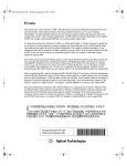
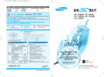
Figure 1-1
V8486A Power Sensor with Accessories and Hardware
2
Chapter 1
V8486A Power Sensor
User’s Guide
General Information
This Operating Manual contains information about initial inspection and
operation of the V8486A Power Sensor.
Warranty
The Power Sensor is warranted and certified as indicated on the last
page of this manual. Do not open the Power Sensor. Any attempt to
disassemble the Power Sensor will void warranty.
Description
The V8486A is a diode-based power sensor. It measures power levels in a
range from −30 dBm to +20 dBm. (Specifications for the Power Sensor
are in Table 1-1.) The V8486A measures at frequencies from 50 GHz to
75 GHz.
The power is determined from the ac voltage developed across the
waveguide termination from the microwave source. The diodes convert
this ac voltage to dc. The dc voltage produced is proportional to the
square of the ac voltage. The dc voltage thus generated is a very low-level
voltage and requires amplification before it can be transferred via the
sensor cable to the power meter.
The amplification is provided by an input amplifier assembly which
consists of a chopper (sampling gate) and an input amplifier. The dc
voltage is routed to the chopper circuit which converts the low-level dc
voltage to an ac voltage. The chopper is driven by a square wave
generated by the power meter. The result is an ac output signal
proportional to the dc input. The ac signal is then amplified by the input
amplifier. The relatively high-level ac signal output can now be routed by
standard cables.
Chapter 1
3
V8486A Power Sensor
User’s Guide
NOTE
The V8486A Power Sensor is compatible with the following power
meters:
435B
E1416A
436A
E4418A/B
437B
E4419A/B
438A
70100A
To obtain optimum accuracy for power measurements above +10 dBm,
when used with the E4418A and E4419A power meters, a firmware
upgrade will be required. Refer to your E4418A and E4419A power
meter’s user’s guide for instructions on how to obtain the revision of the
firmware currently installed in the unit. The firmware revision required
is A1.03.00 (or above) for the E4418A and A2.03.00 (or above) for the
E4419A. Contact your local Agilent Technologies Sales and Service Office
for more information.
In application, the Power Sensor is connected between a microwave
source and a compatible power meter. The Power Sensor provides a
matched load for the microwave source for very low SWR. The power
meter indicates the power dissipated in the load in µW, mW or in dBm.
CAUTION
Do not disassemble the Power Sensor. The Power Sensor is extremely
static-sensitive and can be easily damaged.
Accessories
Included is a hex ball driver plus the waveguide mounting screws. Refer
to Figure 1-1 for a visual check of what should be included with your
power sensor.
4
Chapter 1
V8486A Power Sensor
User’s Guide
Specifications
The specifications listed in Table 1-1 are the performance standards or
limits against which the Power Sensor may be tested.
Table 1-1
Specifications
Characteristics and
Conditions
Limits
Comments
Frequency Range
50 to 75 GHz
Power Range
1 µW to 100 mW (−30 dBm to +20
dBm)
Nominal Impedance
N/A
Waveguide impedance varies
with frequency.
50 MHz Calibration Port
Type N (Male)
50Ω nominal impedance
Waveguide Flange
UG-385/U Flange (Modified)
EIA WR-15
Connectors
Maximum Standing Wave
Ratio (SWR) and Reflection
Coefficient (Rho)
SWR Rho
V8486A
1.06 0.029
When mated to UG-385/U
flange.
Maximum Power
200 mW (average), 40 W (peak) 2
Any port
Worst Case Power Linearity
10 mW to 100 mW (+10 dBm to
+20 dBm) ± 2% for EPM power
meters; +1%, -3% for all other
power meters.
< ± 1% deviation except for
those power ranges noted.
Operating Temperature
Range
0 to 55ºC
Net Weight
0.4 kg
Dimensions
Width: 38 mm Length: 199 mm
Height: 60 mm
1
1. Reflection coefficient (Rho or ρ) relates to SWR according to the following formula:
1 + ρ )SWR = (---------------(1 – ρ)
2. 10 micro-second pulse, 0.5% duty cycle or equivalent such that 200 mW maximum average
power and 40W peak power are not exceeded.
Chapter 1
5
V8486A Power Sensor
User’s Guide
Calibration Factor (CF)
The CAL FACTOR compensates for the frequency response of the sensor.
CAL FACTOR data is provided on a label attached to the sensor cover.
Uncertainties of the CAL FACTOR data are listed in Table 1-2. ISO
expanded uncertainties are calculated based on an NIST-traceable
transfer standard and an analysis of factory test system uncertainties.
To use CAL FACTOR data during power measurements, see "Power
Measurements" in this manual.
Table 1-2
Calibration Factor Uncertainty at 1 mW (0 dBm)
6
Frequency (GHz)
ISO Expanded Uncertainty %1
(coverage factor k=2)
50
4.8
51
6.1
52
5.9
53
5.9
54
5.9
55
4.6
56
6.1
57
6.1
58
6.2
59
6.2
60
4.7
61
6.2
62
6.1
63
6
64
6
65
4.5
66
6.6
67
6.7
68
6.7
69
6.6
70
4.4
Chapter 1
V8486A Power Sensor
User’s Guide
Frequency (GHz)
ISO Expanded Uncertainty %1
(coverage factor k=2)
71
6.7
72
6.8
73
7.0
74
7.3
75
5.1
1.
Refer to Application Note 64-1A: literature number 5965-6630E,
“Fundamentals of RF and Microwave Power Measurements” for more
information regarding ISO expanded uncertainty.
Chapter 1
7
V8486A Power Sensor
User’s Guide
Installation
Initial Inspection
Inspect the shipping container for damage. If the shipping container or
packaging material is damaged, it should be kept until the contents of
the shipment have been checked mechanically and electrically. If there is
mechanical damage or if the instrument does not pass the performance
tests, notify the nearest Agilent Technologies office. Keep the damaged
shipping materials (if any) for inspection by the carrier and a Agilent
Technologies representative.
Interconnections
The V8486A Power Sensor has two inputs: a Type-N connector and a
waveguide flange. During calibration, the Type-N connector is connected
to the calibration port of the power meter. During measurement, the
waveguide flange is connected to the device under test.
CAUTION
Connect the Power Sensor by turning only the nut on the Type-N
connector. Damage can occur if torque is applied to the Power Sensor
body.
The waveguide flanges can be damaged if the flange screws are
over-tightened. Do not fully tighten one flange screw without tightening
the one opposite. First insert screws and tighten until finger tight. If you
are using the hex ball driver, hold the driver between thumb and
forefinger while incrementally tightening screws opposite each other
until reaching a maximum torque of 0.42 N x m.
Use the protective packaging provided with the power sensor to protect it
from dirt and mechanical damage whenever it is not in use. Any burrs,
dents or dirt on the flange or waveguide surface will increase the SWR
and change the Cal Factor.
Refer to the power meter operating and service manual for
interconnecting instructions.
8
Chapter 1
V8486A Power Sensor
User’s Guide
Storage and Shipment
Environment
The instruments should be stored in a clean, dry environment. The
following limitations apply to both storage and shipment:
Temperature. . . . . . . . . . . . . . . . . . . . . . . . . . . . . . . . . −40 to +75°C
Relative Humidity. . . . . . . . . . . . . . . . . . . . . . . . . . . . . <95% @ 40°C
Altitude. . . . . . . . . . . . . . . . . . . . . . . . . . . . . . . . . . . .< 7,600 meters
Original Packaging
Containers and materials identical to those used in factory packaging
are available through Agilent Technologies offices. If the instrument is
being returned to Agilent Technologies for servicing, attach a tag
indicating the type of service required, return address, model number,
and serial number. Also, mark the container FRAGILE to assure careful
handling. In any correspondence, refer to the instrument by model
number and serial number.
Chapter 1
9
V8486A Power Sensor
User’s Guide
Operation
WARNING
BEFORE CONNECTING THE POWER SENSOR TO OTHER
INSTRUMENTS ensure that all instruments are connected to the
protective (earth) ground. Any interruption of the protective
earth grounding will cause a potential shock hazard that could
result in personal injury.
Operating Environment
The operating environment for the Power Sensors should be within the
following limits:
Temperature. . . . . . . . . . . . . . . . . . . . . . . . . . . . . . . . . . . 0 to +55°C
Relative Humidity
. . . . . . . . . . . . . . . . . . . . . . . . . . . . . . . . . .< 95%
Altitude. . . . . . . . . . . . . . . . . . . . . . . . . . . . . . . . . . .
< 4550 meters
Operating Precautions
CAUTION
If the following energy and power levels are exceeded, the power meter
system may be damaged.
❏ Maximum Average Power: 200 mW
❏ Maximum Peak Power: 40 W 1
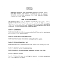
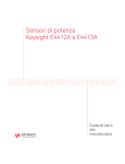
The power sensor has a precision machined V-band waveguide interface.
The size and position of the aperture, the alignment holes and pins, and
the flatness of the mating faces are all very tightly controlled. Refer to
Figure 1-2.
In order to get the best possible measurement results the mating part
must be of similar quality. Connection to a V-band waveguide component
in which the interface dimensions are not accurately controlled can lead
to increased SWR, inaccurate Cal Factor correction, and/or repeatability
1. 10 micro-second pulse, 0.5% duty cycle or equivalent such that
200 mW maximum average power and 40W peak power are not exceeded.
10
Chapter 1
V8486A Power Sensor
User’s Guide
problems. In addition, connections to a well-manufactured but dirty part
can lead to any of the above measurement problems. Conversely, always
insuring connections to parts with clean, high-quality waveguide
interfaces will lead to accurate power measurements over the life of the
product.
CAUTION
Connection to a V-band waveguide component with a dirty, or damaged
flange (e.g. loose particulates, raised metal burrs or bent alignment pins)
can damage the precision interface of the power sensor. Always inspect
and clean the mating part prior to connection.
Figure 1-2
Precision V-band Interface on Front of Power Sensor
Use the protective packaging provided with the sensor to protect the
waveguide connector from dirt and mechanical damage whenever it is
not in use. Any burn, dents or dirt on the flange or waveguide surface
will increase the SWR and change the Cal Factor.
The Type-N connector plastic bead deteriorates when contacted by any
chlorinated or aromatic hydrocarbons such as acetone, trichlorethylene,
carbon tetrachloride, benzene, etc. Clean the connector face with a cotton
swab saturated in isopropyl alcohol.
Chapter 1
11
V8486A Power Sensor
User’s Guide
Power Meter Calibrations
The procedure for calibration may be different for each compatible power
meter. Follow the calibration directions given in your power meter
manual.
Power Measurements
To correct for varying responses at different frequencies a cal factor chart
is included on the Power Sensors. To use the cal factor at the frequency of
interest, adjust the power meter’s CAL FACTOR control according to the
instructions in the power meter’s operating and service manual. This
will automatically correct the power readings.
If you are using a 435B or 436A, the minimum cal factor setting is 85%
and the maximum is 100%. If the cal factor setting for your frequency of
interest is below the meter’s minimum or above the meter’s maximum,
set the cal factor control to 100%, and divide the reading in watts units
by the decimal equivalent of the cal factor. For example, if the cal factor
is 75%, divide the reading by 0.75. (This will result in a larger value of
power than that displayed by the meter.)
If the cal factor is 104%, divide the reading by 1.04. (This will result in a
smaller value of power than that displayed by the meter.)
If reading in dBm, use the chart in Table 1-3 to convert the cal factor to
dB and add this value to the reading. Interpolate for values between
those shown. As above, the cal factor control should be set to 100%. If the
cal factor is 75%, add 1.25 dB to the displayed value. On the other hand,
if the cal factor is 104% subtract 0.17 dB from the displayed reading.
12
Chapter 1
V8486A Power Sensor
User’s Guide
The above procedure has eliminated some mathematical steps; the
following formula may be of some use:
NOTE
Correct dBm = Reading dBm − 10 × Log10 {Cal Factor (decimal)}.
Table 1-3
Cal Factor
Cal
Factor
dB
Cal
Factor
dB
Cal
Factor
dB
70%
1.549
85%
0.706
115%
-0.607
71%
1.487
101%
−0.043
116%
−0.645
72%
1.427
102%
−0.086
117%
−0.682
73%
1.367
103%
−0.128
118%
−0.719
74%
1.308
104%
−0.170
119%
−0.755
75%
1.249
105%
−0.212
120%
-0.792
76%
1.192
106%
−0.253
121%
−0.828
77%
1.134
107%
−0.294
122%
−0.864
78%
1.079
108%
−0.334
123%
−0.899
79%
1.024
109%
−0.374
124%
−0.934
80%
0.969
110%
−0.414
125%
−0.969
81%
0.915
111%
−0.453
126%
−1.004
82%
0.862
112%
−0.492
127%
−1.038
83%
0.809
113%
−0.531
128%
−1.072
84%
0.757
114%
−0.569
129%
−1.106
130%
−1.139
Chapter 1
13
V8486A Power Sensor
User’s Guide
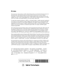
Figure 1-3
Typical Influence of Temperature on Sensitivity
The sensitivity of the power sensor is influenced by ambient
temperature. The sensor should be calibrated at the temperature of
operation to obtain the most accurate results. Typical temperature
sensitivity variations are shown in Figure 1-3.
Operating Instructions
To operate the Power Sensor, refer to the operating instructions in of the
power meter operating and service manual.
NOTE
If having an open RF connection on your system is a concern, terminate
the sensor Type-N calibration port with a 50Ω load.
Modulation Effects
When measuring microwave sources that are modulated at the chopper
frequency (nominally 220 Hz for the 43X family and 217 Hz for the
E4418A/B and E4419A/B), or at the first or second harmonic or
submultiples of the chopper frequency, beat notes will occur. Unless the
modulation rate is exactly the chopper frequency, they can usually be
eliminated by averaging since the amplitudes are centered on the actual
power. These frequencies may also be avoided by changing the
modulation frequency slightly, if possible.
If you are using an 437B, E4418A/B or E4419A/B Power Meter, a filter
setting of 128 will minimize most beat note interference. To minimize
beat note interference using a 438A Power Meter select a filter number of
at least 7.
14
Chapter 1
V8486A Power Sensor
User’s Guide
Linearity Correction
For most 8480 series power sensors the correct (A type or D type)
linearity correction table is automatically selected. However, when you
use the V8486A power sensor with EPM power meters, you must
override the automatic selection and select the D-type correction. This
procedure provides optimum accuracy when making power
measurements >+10dBm. Subsequent connection of another
A-type sensor will result in a warning message stating the “Linearity
Override May be Required”.
To select the linearity type to be applied:
E4418B
Press [System Inputs], Tables, Linearity ATyp DTyp.
E4419B
Press [System Inputs], Tables, A Linearity ATyp DTyp or B Linearity
ATyp DTyp.
NOTE
For use with the E4418A and E4419A power meters, a firmware upgrade
will be required. Refer to your E4418A and E4419A power meter’s user’s
guide for instructions on how to obtain the revision of the firmware
currently installed in the unit. The firmware revision required is
A1.03.00 (or above) for the E4418A and A2.03.00 (or above) for the
E4419A. Contact your local Agilent Technologies Sales and Service Office
for further information.
Chapter 1
15
V8486A Power Sensor
User’s Guide
Performance Tests
This section does not establish SWR test procedures since there are
several test methods and different equipment available for testing the
SWR or reflection coefficient. Therefore, the actual accuracy of the test
equipment, all source match corrections, and all harmonics must be
accounted for when measuring against instrument specifications to
determine a pass or fail condition.
To measure the SWR across the waveguide band, use a directional
coupler and detector selected for the band of interest. The directional
coupler should have a directivity greater than 36 dB, such as the
V752C/D. The detector should have greater than 0.4 mV/µW sensitivity
and should be calibrated with a rotary vane attenuator with an accuracy
of 2%. Incident power should be less than +20 dBm. A convenient source
is a frequency multiplier driven by an 8360 B-Series swept signal
generator.
To check the calibration factor, the Power Sensor should be compared
with another recently calibrated power sensor. The source should be
leveled with a reference coupler that has low SWR and high directivity to
monitor or level the incident power.
For calibration factor and error analysis we suggest Application Note
64-1A: literature number 5965-6630E, "Fundamentals of RF and
Microwave Power Measurements".
16
Chapter 1
V8486A Power Sensor
User’s Guide
Replaceable Parts
The part numbers of the hex ball driver and the hardware are listed in
Figure 1. In addition, the following protective parts are replaceable:
Table 1-4
Replaceable Parts
Part Number
1401-0214
08486-40103
Description
Usage
protective cap
Type-N connector
protective cover
V-band waveguide flange
There are no other replaceable parts for this product.
A listing of Agilent Technologies sales and service offices is located at the
end of this manual.
Repair and Adjustments
Do not attempt to repair or adjust the Power Sensor. Due to the extreme
static sensitivity of the Power Sensor, customer repair is not
recommended. If your Power Sensor should fail or need calibration,
return it to Agilent Technologies.
CAUTION
Do not disassemble the Power Sensor. The Power Sensor is extremely
static sensitive and can be easily damaged. If the Power Sensor shows
evidence of attempted customer repair, the warranty may be voided.
Chapter 1
17
V8486A Power Sensor
User’s Guide
By internet, phone, or fax, get assistance with all your test and measurement needs.
Table 1-5
Contacting Agilent
Online assistance: www.agilent.com/find/assist
United States
(tel) 1 800 829 4444
Latin America
(tel) (305) 269 7500
(fax) (305) 269 7599
Canada
(tel) 1 877 894
4414
(fax) (905)
282-6495
New Zealand
(tel) 0 800 738 378
(fax) (+64) 4 495 8950
Japan
(tel) (+81) 426 56 7832
(fax) (+81) 426 56
7840
Australia
(tel) 1 800 629 485
(fax) (+61) 3 9210
5947
Europe
(tel) (+31) 20 547
2323
(fax) (+31) 20 547
2390
Asia Call Center Numbers
Country
Phone Number
Fax Number
Singapore
1-800-375-8100
(65) 836-0252
Malaysia
1-800-828-848
1-800-801664
Philippines
(632) 8426802
1-800-16510170 (PLDT
Subscriber Only)
(632) 8426809
1-800-16510288 (PLDT
Subscriber Only)
Thailand
(088) 226-008 (outside
Bangkok)
(662) 661-3999 (within
Bangkok)
(66) 1-661-3714
Hong Kong
800-930-871
(852) 2506 9233
Taiwan
0800-047-866
(886) 2 25456723
People’s
Republic of
China
800-810-0189 (preferred)
10800-650-0021
10800-650-0121
India
1-600-11-2929
000-800-650-1101
18
Chapter 1
V8486A Power Sensor
User’s Guide
Warranty
This Agilent Technologies instrument product is warranted against
defects in material and workmanship for a period of 1 year from date of
shipment. During the warranty period, Agilent Technologies will, at its
option, either repair or replace products which prove to be defective.
For warranty service or repair, this product must be returned to a service
facility designated by Agilent Technologies. Buyer shall prepay shipping
charges to Agilent Technologies and Agilent Technologies shall pay
shipping charges to return the product to Buyer. However, Buyer shall
pay all shipping charges, duties, and taxes for products returned to
Agilent Technologies from another country.
Agilent Technologies warrants that its software and firmware designated
by Agilent Technologies for use with an instrument will execute its
programming instructions when properly installed on that instrument.
Agilent Technologies does not warrant that the operation of the
instrument, or software, or firmware will be uninterrupted or error-free.
Limitation of Warranty
The foregoing warranty shall not apply to defects resulting from
improper or inadequate maintenance by Buyer, Buyer-supplied software
or interfacing, unauthorized modification or misuse, operation outside of
the environmental specifications for the product, or improper site
preparation or maintenance.
NO OTHER WARRANTY IS EXPRESSED OR IMPLIED. AGILENT
TECHNOLOGIES SPECIFICALLY DISCLAIMS THE IMPLIED
WARRANTIES OF MERCHANTABILITY AND FITNESS FOR A
PARTICULAR PURPOSE.
Exclusive Remedies
THE REMEDIES PROVIDED HEREIN ARE BUYER’S SOLE AND
EXCLUSIVE REMEDIES. AGILENT TECHNOLOGIES SHALL NOT
BE LIABLE FOR ANY DIRECT, INDIRECT, SPECIAL, INCIDENTAL,
OR CONSEQUENTIAL DAMAGES, WHETHER BASED ON
CONTRACT, TORT, OR ANY OTHER LEGAL THEORY.
Chapter 1
19
Index
A
adjustments, 17
C
cal factor, 13
calibration factor, 6
calibration factor uncertainty, 6
calibrations
power meter, 12
CF, 6
connections, 8
connectors, 5
D
dimensions, 5
F
frequency range, 5
O
operating
environment, 10
precautions, 10
temperature range, 5
operating environment, 10
operating precautions, 10
operating temperature range, 5
V
V-band interface, 11
W
warranty, 3, 19
worst case power linearity, 5
P
packaging, 9
performance tests, 16
power
maximum, 5
worst case linearity, 5
power measurements, 12
power meter calibrations, 12
power range, 5
R
repair, 17
replaceable parts, 17
Rho, 5
I
interface
V-band, 11
L
linearity correction, 15
S
specifications, 5
standing wave ratio, 5
storage, 9
M
marker, 4
maximum power, 5
measurements
power, 12
modulation effects, 14
T
temperature
operating range, 5
tests
performance, 16
N
net weight, 5
nominal impedance, 5
U
uncertainty
calibration factor, 6
20
Index