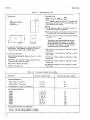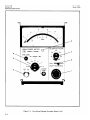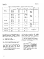
1
Errata This manual may contain references to HP or Hewlett-Packard. Please note that Hewlett-Packard's former test and measurement, semiconductor products and chemical analysis businesses are now part of Agilent Technologies. To reduce potential confusion, the only change to product numbers and names has been in the company name prefix: where a product number/name was HP XXXX the current name/number is now Agilent XXXX. For example, model number HP8648 is now model number Agilent 8648. Ce manuel peut contenir des références à <<HP>> ou <<Hewlett-Packard.>> Veuillez noter que les produits de test et mesure, de semi-conducteur et d'analyse chimique qui avaient fait partie de la société Hewlett-Packard sont maintenent une partie de la société Agilent Technologies. Pour reduire la confusion potentielle, le seul changement aux noms de reference a été dans le préfixe de nom de société : là où un nom de référence était HP XXXX, le nouveau nom de référence est maintenant Agilent XXXX. Par example, le HP 8648 s'appelle maintenent Agilent 8648. Diese Gebrauchsanweiseung kann Bezug nehmen auf die Namen HP oder Hewlett-Packard. Bitte beachten Sie, dass ehemalige Betriebsbereiche von Hewlett-Packard wie HP-Halbleiterprodukte, HP-chemische Analysen oder HP-Test- und Messwesen nun zu der Firma Agilent Technology gehören. Um Verwirrung zu vermeiden wurde lediglich bei Produktname und - Nummer der vo laufende Firmenname geändert: Produkte mit dem Namen/Nummer HP XXXX lauten nun mehr Agilent XXXX. Z.B, das Modell HP 8648 heißt nun Agilent 8648. Questo manuale potrebbe contenere riferimenti ad HP o Hewlett-Packard. Si noti che le attività precedentemente gestite da Hewlett-Packard nel campo di Test & Misura, Semiconduttori, ed Analisi Chimica sono ora diventate parte di Agilent Technologies. Al fine di ridurre il rischio di confusione, l'unica modifica effettuata sui numeri di prodotto e sui nomi ha riguardato il prefisso con il nome dell'azienda : dove precedentemente compariva "HP XXXX" compare ora "Agilent XXXX". Ad esempio: il modello HP8648 è ora indicato come Agilent 8648. Este manual puede hacer referencias a HP o Hewlett Packard. Las organizaciones de Prueba y Medición (Test and Measurement), Semiconductores (Semiconductor Products) y Análisis Químico (Chemical Analysis) que pertenecían a Hewlett Packard, ahora forman parte de Agilent Technologies. Para reducir una potencial confusión, el único cambio en el número de producto y nombre, es el prefijo de la compañía: Si el producto solía ser HP XXXX, ahora pasa a ser Agilent XXXX. Por ejemplo, el modelo HP8648 es ahora Agilent 8648. 䖭Ͼݠ䞠䴶ৃ㛑᳝ᚴ᱂݀ৌⱘ䌘᭭DŽ䇋⊼ᛣᚴ᱂݀ৌҹࠡⱘ⌟䆩ˈञᇐԧѻ કˈ࣪ᄺߚᵤ䚼䮼⦄ሲѢᅝ᥋Ӻ݀ৌDŽЎњޣᇥৃ㛑ⱘ䇃㾷ˈѻકোⷕৡᄫ াᬍব᳔ࠡ䴶ⱘ݀ৌৡᄫDŽབᵰϔϾѻકⱘোⷕˋৡᄫҹࠡᰃ+3;;;;ˈ⦄ⱘ োⷕˋৡᄫᰃᅝ᥋Ӻ;;;;DŽ՟བൟোⷕᰃᚴ᱂˔˒ː˔DŽ⦄ᰃൟোⷕᅝ ᥋Ӻ˔˒ː˔DŽ Document Part Number 5971-2668 Printed in Malaysia September 2004 A Table of Contents Model 432A TABLE OF CONTENTS Section Page I GENERAL INFORMATION. . . . . . . . . . . . . 1-1. Description . . . . . . . . . . . . . . . . . . . . . 1-5. Instrument Identification. . . . . . . . . . 1-7. Operating Environment . . . . . . . . . . . 1-11. Cooling Requirements . . . . . . . . . 1-13. Cleaning . . . . . . . . . . . . . . . . . . . . 1-1 1-1 1-1 1-3 1-3 1-3 II INSTALLATION . . . . . . . . . . . . . . . . . . . . . . 2-1. Initial Inspection. . . . . . . . . . . . . . . . . 2-2. Mechanical Check . . . . . . . . . . . . 2-4. Performance Checks . . . . . . . . . . 2-6. Damage Claims . . . . . . . . . . . . . . 2-9. Three-Conductor Power Cable . . . . . . 2-12. Primary Power Requirements . . . . . . 2-14. Internal Battery Operation . . . . . . . . 2-16. Battery Installation . . . . . . . . . . . 2-17. Battery Storage . . . . . . . . . . . . . . 2-19. Rack Mounting . . . . . . . . . . . . . . . . . . 2-21. Combining Case . . . . . . . . . . . . . . 2-23. Adapter Frames . . . . . . . . . . . . . . 2-25. Repacking for Shipment . . . . . . . . . . . 2-1 2-1 2-1 2-1 2-1 2-1 2-1 2-1 2-1 2-1 2-1 2-1 2-2 2-2 III OPERATING INFORMATION. . . . . . . . . . . 3-1. Introduction. . . . . . . . . . . . . . . . . . . . . 3-4. Controls, Connectors and Indicators . 3-12. Battery Operation. . . . . . . . . . . . . . . . 3-17. Microwave Power Measurement Accuracy . . . . . . . . . . . . . . . . . . . . 3-23. Calibrator Factor and Effective Efficiency . . . . . . . . . . . . . . . . . . . 3-27. Precision Power Measurement. . . . . . 3-28. General. . . . . . . . . . . . . . . . . . . . . 3-30. Measurement Procedure . . . . . . . 3-1 3-1 3-1 3-1 IV V ii MAINTENANCE (Cont) 5-14. 432A Performance Tests with 8477A Calibrator . . . . . . . . . . . . . . . 5-1 5-15. Initial Setup . . . . . . . . . . . . . . . . . 5-1 5-16. Meter Accuracy Test . . . . . . . . . . 5-1 5-17. Calibration Factor Test . . . . . . . . 5-2 5-18. Meter Linearity Check. . . . . . . . . 5-2 5-19. Zero Carryover Test . . . . . . . . . . . 5-2 5-20. Fine Zero Range Check . . . . . . . . 5-3 5-21. 432A Calibration Without 8477A Calibrator . . . . . . . . . . . 5-3 5-24. Calibration Procedure 1. . . . . . . . 5-3 5-26. Calibration Procedure 2. . . . . . . . 5-9 5-27. Cover Removal and Replacement. . . . 5-9 5-29. Top Cover Removal . . . . . . . . . . . 5-9 5-30. Top Cover Replacement. . . . . . . . 5-9 5-31. Bottom Cover Removal . . . . . . . . 5-9 5-32. Bottom Cover Replacement . . . . . 5-9 5-33. Adjustment Procedures. . . . . . . . . . . 5-10 5-34. Initial Setup . . . . . . . . . . . . . . . . 5-10 5-35. Mechanical Meter Adjustment . . . . . . . . . . . . . . 5-10 5-36. Bridge Amplifier Tests. . . . . . . . 5-10 5-37. Meter and Recorder Output Calibration. . . . . . . . . . . . . . . 5-10 5-38. Battery Charger Adjustment (Option 01 Only) . . . . . . . . . . 5-11 5-39. Battery Removal . . . . . . . . . . . . 5-11 5-40. Isolating Trouble in Transistor Circuits . . . . . . . . . . . . . . . . . . . . 5-11 5-46. Out-of-Circuit Testing . . . . . . . . 5-13 5-48. Component Replacement in Etched Circuits . . . . . . . . . . . . . 5-13 5-50. Axial-Lead Components . . . . . . 5-13 5-52. Other Components . . . . . . . . . . . 5-14 VI REPLACEABLE PARTS . . . . . . . . . . . . . . . . 6-1 6-1. Introduction. . . . . . . . . . . . . . . . . . . . . 6-1 6-3. Ordering Information . . . . . . . . . . . . . 6-1 VII TROUBLESHOOTING, SCHEMATICS, AND COMPONENT LOCATIONS . . . . . 7-1 7-1. Introduction. . . . . . . . . . . . . . . . . . . . . 7-1 7-5. Troubleshooting. . . . . . . . . . . . . . . . . . 7-1 7-8. Schematics. . . . . . . . . . . . . . . . . . . . . . 7-1 7-12. A1A1 Auto Zero Assembly . . . . . . . . . 7-1 7-14. Test Conditions . . . . . . . . . . . . . . . . . . 7-1 3-2 3-2 3-2 3-2 5-1 5-1 5-1 5-1 5-1 5-1 5-1 Page V 3-2 PRINCIPLES OF OPERATION . . . . . . . . . . 4-1 4-1. Simplified Description . . . . . . . . . . . . 4-1 4-5. Functional Block Diagram . . . . . . . . . 4-1 MAINTENANCE . . . . . . . . . . . . . . . . . . . . . . 5-1. Introduction. . . . . . . . . . . . . . . . . . . . . 5-3. Content . . . . . . . . . . . . . . . . . . . . . . . . 5-4. Performance Tests . . . . . . . . . . . . 5-6. Adjustments . . . . . . . . . . . . . . . . . 5-10. Test Equipment . . . . . . . . . . . . . . 5-12. Service Information . . . . . . . . . . . Section Model 432A List of Tables List of Illustrations LIST OF TABLES Number 1–1. 1–2. 5–1. 5–2. 5–3. 5–4. 5–5. 5–6. 5–7. 6–1. 6–2. 7–1. Title Page Specifications . . . . . . . . . . . . . . . . . . . . . . . . 1–1 Thermistor Mounts for the 432A . . . . . . . . . 1–2 Recommended Test Equipment . . . . . . . . . . 5–0 Meter Accuracy Test . . . . . . . . . . . . . . . . . . . 5–2 Calibration Factor Test . . . . . . . . . . . . . . . . 5–2 Performance Test Card. . . . . . . . . . . . . . . . . 5–5 Out-of-Circuit Transistor Resistance Measurements . . . . . . . . . . . . . . . . . 5–11 Etched Circuit Soldering Equipment. . . . . 5–13 Safe Ohmmeter Range for Transistor Resistance Measurements . . . . . . . . 5–14 Replaceable Parts . . . . . . . . . . . . . . . . . . . . . 6–2 Code List of Manufacturers . . . . . . . . . . . . . 6–6 Schematic Notes . . . . . . . . . . . . . . . . . . . . . . 7–2 Number 7–2. 7–3. 7–4. 7–5. 7–6. 7–7. 7–8. 7–9. 7–10. 7–11. 7–12. Title Page Overall Troubleshooting. . . . . . . . . . . . . . . . RF Bridge Troubleshooting . . . . . . . . . . . . . Compensation Bridge Troubleshooting . . . . Auto-Zero Troubleshooting. . . . . . . . . . . . . . Chopping and Summing Circuit Troubleshooting . . . . . . . . . . . . . . . . . 5 kHz Multivibrator Troubleshooting . . . . . Range Amplifier Troubleshooting . . . . . . . . Calibrator Factor Amplifier Troubleshooting . . . . . . . . . . . . . . . . . Pulse Width Modulator and Meter Troubleshooting . . . . . . . . . . . . . . . . . Battery Charger Troubleshooting . . . . . . . . Power Supply Troubleshooting . . . . . . . . . . 7–5 7–6 7–6 7–7 7–7 7–7 7–7 7–7 7–7 7–9 7–9 LIST OF ILLUSTRATIONS Number 1–1. 1–2. 2–1. 2–2. 3–1. 3–2. 3–3. 3–4. 4–1. 4–2. 4–3. 4–4. 4–5. 5–1. 5–2. 5–3. 5–4. Title Page HP Model 432A Power Meter. . . . . . . . . . . . 1–0 Instrument Identification. . . . . . . . . . . . . . . 1–1 Sub-module Installation in Rack Adapter Frame . . . . . . . . . . . . . . . . . . . . . . . . . 2–2 HP Model 1051A Combining Case Instrument Installation . . . . . . . . . . . 2–2 Precision Power Measurements . . . . . . . . . . 3–3 Front Panel Controls, Connectors and Indicators . . . . . . . . . . . . . . . . . . . . . . 3–4 Rear Panel Controls and Connectors. . . . . . 3–6 Turn On and Zeroing Procedure . . . . . . . . . 3–8 Model 432A Simplified Block Diagram . . . . 4–0 Model 432A Block Diagram . . . . . . . . . . . . . 4–3 Model 432A RF Bridge Talking Schematic . . . . . . . . . . . . . . . . . . . . . . 4–4 Model 432A Meter Logic Talking Schematic . . . . . . . . . . . . . . . . . . . . . . 4–6 Model 432A Power Supply Talking Schematic . . . . . . . . . . . . . . . . . . . . . . 4–8 Check and Adjustment Test Setup . . . . . . . 5–1 Zero Carryover Test Setup . . . . . . . . . . . . . . 5–3 Bridge Amplifier Test . . . . . . . . . . . . . . . . . 5–10 Transistor Biasing and Operating Characteristics . . . . . . . . . . . . . . . . . 5–12 Number 7–1. 7–2. 7–3. 7–4. 7–5. 7–6. 7–7. 7–8. 7–9. 7–10. 7–11. 7–12. 7–13. 7–14. 7–15. 7–16. Title Page Servicing Block Diagram . . . . . . . . . . . . . . . 7–3 Model 432A Top Internal View . . . . . . . . . . 7–4 Model 432A Waveforms . . . . . . . . . . . . . . . . 7–4 Model 432A Test Point Locations . . . . . . . . 7–5 Model 432A Bottom View, Component Locations . . . . . . . . . . . . . . . . . . . . . . 7–6 Model 432A Front Panel Interior. . . . . . . . . 7–6 A1 Bridge Assembly, Component Locations . . . . . . . . . . . . . . . . . . . . . 7–10 Model 432A Rear Panel Interior . . . . . . . . 7–10 RF and Compensation Bridge Schematic Diagram . . . . . . . . . . . . . 7–11 Model 432A Switches . . . . . . . . . . . . . . . . . 7–12 A2 Meter Logic Assembly, Component Locations . . . . . . . . . . . . . . . . . . . . . 7–13 Meter Logic Schematic Diagram . . . . . . . . 7–13 A2 Meter Logic Assembly, Power Supply Component Locations . . . . . . . . . . . 7–15 A7 Battery Charging Circuit (Option 01) Component Locations . . . . . . . . . . . 7–15 Power Supply, Schematic Diagram . . . . . . 7–15 Thermistor Cable Wiring Diagram . . . . . . 7–16 iii Regulatory Information Model 432A Declaration of Conformity according to ISO/IEC Guide 22 and EN45014 Manufacturer’s Name: Manufacturer’s Address: Hewlett-Packard Ltd. Queensferry Microwave Division South Queensferry West Lothian, EH30 9TG Scotland, United Kingdom Declares that the product Product Name: Thermistor Power Meter Model Numbers: HP 432A Product Options: This declaration covers only the standard option of the above product. Conforms with the protection requirements of European Council Directive 89/336/EEC on the approximation of the laws of the member states relating to electromagnetic compatibility. Against EMC test specifications EN 55011:1991 (Group 1, Class A) and EN 50082-1:1992 As Detailed in: Electromagnetic Compatibility (EMC) Technical Construction File (TCF) No. A-5951-9852-02 Assessed by: DTI Appointed Competent Body EMC Test Centre, GEC-Marconi Avionics Ltd., Maxwell Building, Donibristle Industrial Park, KY11 5LB Scotland, United Kingdom Technical Report Number:6893/2200/CBR, dated 23 September 1997 Supplementary Information: The product conforms to the following safety standards: EN 61010-1(1993) / IEC 1010-1(1990) +A1(1992) +A2(1994) CSA-C22.2 No. 1010.1-93 The product herewith complies with the requirements of the Low Voltage Directive 73/23/EEC, and carries the CE-marking accordingly. South Queensferry, Scotland Location iv 17 November 1997 Date R.M. Evans / Quality Manager Model 432A Regulatory Information Warranty This Hewlett-Packard product is warranted against defects in materials and workmanship for a period of one year from date of shipment. During the warranty period, Hewlett-Packard Company will, at its option, either repair or replace products which prove to be defective. For warranty service or repair, this product must be returned to a service facility designated by HP. Buyer shall prepay shipping charges to HP and HP shall pay shipping charges to return the product to Buyer. However, Buyer shall pay all shipping charges, duties, and taxes for products returned to HP from another country. HP warrants that its software and firmware designated by HP for use with an instrument will execute its programming instructions when properly installed on that instrument. HP does not warrant that the operation of the instrument, or software, or firmware will be uninterrupted or error free. Limitation of Warranty The foregoing warranty shall not apply to defects resulting from: 1 Improper or inadequate maintenance, adjustment, calibration, or operation by Buyer; 2 Buyer-supplied software, hardware, interfacing or consumables; 3 Unauthorized modification or misuse; 4 Operation outside of the environmental and electrical specifications for the product; 5 Improper site preparation and maintenance; or 6 Customer induced contamination or leaks. THE WARANTY SET FORTH IS EXCLUSIVE AND NO OTHER WARRANTY, WHETHER WRITTEN OR ORAL, IS EXPRESSED OR IMPLIED. HP SPECIFICALLY DISCLAIMS THE IMPLIED WARRANTIES OF MERCHANTABILITY AND FITNESS FOR A PARTICULAR PURPOSE. Limitation of Remedies and Liability THE REMEDIES PROVIDED HEREIN ARE BUYER'S SOLE AND EXCLUSIVE REMEDIES. IN NO EVENT SHALL HP BE LIABLE FOR DIRECT, INDIRECT, SPECIAL, INCIDENTAL, OR CONSEQUENTIAL DAMAGES (INCLUDING LOSS OF PROFITS) WHETHER BASED ON CONTRACT, TORT OR ANY OTHER LEGAL THEORY. Responsibilities of the Customer The customer shall provide: 1 Access to the products during the specified periods of coverage to perform maintenance. 2 Adequate working space around the products for servicing by Hewlett-Packard personnel. 3 Access to and use of all information and facilities determined necessary by Hewlett-Packard to service and/or maintain the products. (Insofar as these items may contain proprietary or classified information, the customer shall assume full responsibility for safeguarding and protection from wrongful use.) 4 Routine operator maintenance and cleaning as specified in this manual. 5 Consumables such as paper, disks, magnetic tapes, ribbons, inks, pens, gases, solvents, lamps, filters, fuses, seals, etc. v Regulatory Information Model 432A Certification Hewlett-Packard Company certifies that this product met its published specifications at the time of shipment from the factory. Hewlett-Packard further certifies that its calibration measurements are traceable to the United States National Bureau of Standards, to the extent allowed by the Bureau's calibration facility, and to the calibration facilities of other International Standards Organization members. Assistance Product maintenance agreements and other customer assistance agreements are available for Hewlett-Packard products. For any assistance, contact your Hewlett-Packard Sales and Service Office. Addresses are provided at the back of this manual. Notice The information contained in this document is subject to change without notice. Hewlett-Packard shall not be liable for errors contained herein or for incidental or consequential damages in connection with the furnishing, performance or use of this material. This document contains proprietary information which is protected by copyright. All rights are reserved. No part of this document may be photocopied or reproduced without the prior written consent of the manufacturer, Hewlett-Packard Ltd. Restricted Rights Legend Use, duplication, or disclosure by the government is subject to restrictions as set forth in subdivision (b)(3)(ii) of the Rights in Technical Data and Computer Software clause at 52.2277013. Hewlett-Packard Company; 3000 Hanover Street; Palo Alto, California 94304. Statement of Compliance Electromagnetic This product has been designed to meet the protection requirements of the European Compatibility (EMC) Communities Electromagnetic Compatibility (EMC) directives: Information EN55011:1991 (Group 1, Class A) EN50082-1:1992 - IEC 1000-4-2 (1995) ESD - IEC 1000-4-3 (1995) Radiated Suseptibility - IEC 1000-4-4 (1995) EFT In order to preserve the EMC performance of the product, any cable which becomes worn or damaged must be replaced with the same type and specification. Safety Information vi This instrument has been designed and tested in accordance with publication EN61010-1(1993) / IEC 1010-1(1990) +A1(1992) +A2(1994) / CSA C22.2 No. 1010.1(1993) Safety Requirements for Electrical Equipment for Measurement, Control and Laboratory Use, and has been supplied in a safe condition. The instruction documentation contains information and warnings which must be followed by the user to ensure safe operation and to maintain the instrument in a safe condition. Model 432A Regulatory Information General Safety The following general safety precautions must be observed during all phases of operation, service, and repair of this instrument. Failure to comply with these precautions or with specific warnings elsewhere in this manual violates safety standards of design, manufacture, and intended use of the instrument. Hewlett-Packard Company assumes no liability for the customer’s failure to comply with these requirements. WARNING This is a Safety Class I instrument (provided with a protective earthing ground, incorporated in the powercord). The mains plug shall only be inserted in a socket outlet provided with a protective earth contact. Any interruption of the protective conductor inside or outside of the instrument is likely to make the instrument dangerous. Intentional interruption is prohibited. DO NOT operate the product in an explosive atmosphere or in the presence of flammable gasses or fumes. DO NOT use repaired fuses or short-circuited fuseholders: For continued protection against fire, replace the line fuse(s) only with fuse(s) of the same voltage and current rating and type. DO NOT perform procedures involving cover or shield removal unless you are qualified to do so: Operating personnel must not remove equipment covers or shields. Procedures involving the removal of covers and shields are for use by service-trained personnel only. DO NOT service or adjust alone: Under certain conditions, dangerous voltages may exist even with the equipment switched off. To avoid dangerous electrical shock, service personnel must not attempt internal service or adjustment unless another person, capable of rendering first aid and resuscitation, is present. DO NOT operate damaged equipment: Whenever it is possible that the safety protection features built into this product have been impaired, either through physical damage, excessive moisture, or any other reason, REMOVE POWER and do not use the product until safe operation can be verified by service-trained personnel. If necessary, return the product to a Hewlett-Packard Sales and Service Office for service and repair to ensure the safety features are maintained. DO NOT substitute parts or modify equipment: Because of the danger of introducing additional hazards, do not install substitute parts or perform any unauthorized modification to the product. Return the product to a Hewlett-Packard Sales and Service Office for service and repair to ensure the safety features are maintained. vii Regulatory Information Model 432A Safety Symbols The following symbols on the instrument and in the manual indicate precautions which must be taken to maintain safe operation of the instrument. Safety Symbols The Instruction Documentation Symbol. The product is marked with this symbol when it is necessary for the user to refer to the instructions in the supplied documentation. Indicates the field wiring terminal that must be connected to earth ground before operating the equipment - protects against electrical shock in case of fault. Frame or chassis ground terminal - typically connects to the equipment's metal frame. Alternating current (AC) Direct current (DC) Indicates hazardous voltages WARNING Warning denotes a hazard. It calls attention to a procedure which, if not correctly performed or adhered to, could result in injury or loss of life. Do not proceed beyond a warning note until the indicated conditions are fully understood and met. CAUTION Caution denotes a hazard. It calls attention to a procedure which, if not correctly performed or adhered to, could result in damage to or destruction of the instrument. Do not proceed beyond a caution note until the indicated conditions are fully understood and met. The CE mark shows that the product complies with all relevant European Legal Directives. ISM 1-A This is a symbol of an Industrial, Scientific, and Medical Group 1 Class A product. The CSA mark is a registered trademark of the Canadian Standards Association, and indicates compliance to the standards layed out by them. viii Model 432A Regulatory Information Noise Declaration LpA<70dB am Arbeitsplatz (operator position) normaler Betrieb (normal position) nach DIN 45635 pt.19 (per ISO 7779) ix Model 432A Section I SECTION I GENERAL INFORMATION 1-1. DESCRIPTION. 1-5. 1–2. The Hewlett-Packard Model 432A Power Meter, with HP temperature-compensated thermistor mounts, measures RF power from 10 microwatts (-20 dBm) to 10 milliwatts (+10 dBm) full scale with 1% of full scale accuracy from 10 MHz to 40 GHz. With a selector switch, the instrument normalizes the power meter reading to compensate for the Callibration Factor of a thermistor mount used for a given measurement. For portable operation, Option 01 instruments have a rechargeable nickel-cadmium battery. See Table 1–1 for complete specifications. INSTRUMENT IDENTIFICATION. 1–6. Hewlett-Packard instruments are identified by an 8- or 10digit serial number. The first four digits are the Serial Prefix. To properly match a manual with the instrument to which it applies, the prefix on the instrument must be the same as the prefix at the front of the manual. If the numbers are different, information is supplied either on yellow Manual Change Supplements, or in an Appendix in the Manual. If the change information is missing, contact your HP Sales Office (Sales Offices are listed at the back of the Manual). 1–3. The Model 432A has provision for dc substitution measurements and for power meter calibration. An output is provided for recorders or digital voltmeter readout. 1–4. Accessories. Two accessories are supplied with the Model 432A Power Meter: a 7.5-foot (2290 mm) detachable power cable and a 5-foot (1520 mm) cable that connects the thermistor mount to the meter. Thermistor mounts are available but not supplied with the Power Meter (refer to Table 1–2). Table 1–1 lists those accessories supplied and also those available. Table 1-1. Instrument Type: Automatic, self-balancing power meter for use with temperature-compensated thermistor mount. Power Range: 7 ranges with full-scale readings of 10, 30, 100, and 300 µW, 1, 3 and 10 mW; also calibrated in dBm from -20 dBm to +10 dBm full scale in 5-dB steps. Accuracy: ±1% of full scale on all ranges (+0˚C to +55˚C). Calibration Factor Control: 13-position switch normalizes meter reading to account for thermistor mount Calibration Factor. Range: 100% to 88% in 1% steps. Thermistor Mount: External temperature-compensated thermistor mounts required for operation (see Table 1-2). Meter: Taut-band suspension, individually computercalibrated, mirror-backed scales. Milliwatt scale more than 4-1/4 inches (108 mm) long. Zero Carryover: Less than ±0.5% of full scale when zeroed on most sensitive range. SERIAL PREFIX HEWLETT - PACKARD COMPANY SER. 1234A98765 MADE IN U.S.A. Figure 1-2. Instrument Identification Specifications Fine Zero: Automatic, operated by toggle switch. Recorder Output: 1.000 volt into open circuit corresponds to full-scale meter deflection (1.0 on 0 - 1 scale) ±0.5%; 1000-ohm output impedance, BNC connector. RFI: Meets all conditions specified in MIL-I-6161D. Power: 115 or 230 Vac ±10%, 48 to 440 Hz, 13 VA (max). Optional rechargeable battery provides up to 20 hours continuous operation. Automatic battery recharge. Weight: Net 6-1/2 lb (3 kg). Weight with Optional Battery Pack: Net 9-1/4 lb (4.2 kg). Environmental: Operating Temperature: 0 to +55˚C. Storage Temperature: -20 to +60˚C. Humidity: Up to 95% Relative Humidity at 40˚C. EMC: Meets EN55011:1991 (Group 1, Class A), and EN50082-1. 1-1 Model 432A 1-7. Section I OPERATING ENVIRONMENT. CAUTION Mains supply voltage fluctuations should not exceed ±10% of the nominal selected line voltage. CAUTION Before switching on this instrument, make sure that the line voltage slide switch is set to the voltage of the power supply, and the correct fuse is installed (see Figure 3–3). Ensure the power supply voltage is in the specified range. WARNING Appliance coupler (mains input powercord) is the power disconnect device. Do not position the instrument such that access to the coupler is impaired. WARNING For continued protection against fire hazard, replace the line fuse only with the same type and line rating (T100 mA 250 V). The use of other fuses or materials is prohibited. WARNING If this instrument is not used as specified, the protection provided by the equipment could be impaired. This instrument must be used in a normal condition only (in which all means for protection are intact). WARNING No operator serviceable parts inside. Refer servicing to qualified personnel. To prevent electrical shock do not remove covers. 1–8. This instrument is designed for indoor use only. 1–9. The module may be operated at temperatures from 0˚C to 55˚C at altitudes of up to 4,600 m (15,000 ft). The module may be operated in environments up to 95% relative humidity to 40˚C, but it should be protected from temperature extremes which may cause condensation. 1–10. To ensure adequate cooling do not obstruct air vents in the instrument cabinet. 1–11. COOLING REQUIREMENTS. 1–12. To provide adequate cooling, an air gap of approximately 75 mm should be maintained around the instrument. NOTE If the HP 432A is subject to HP Class B condensation it is recommended that the instrument be powered up for at least 30 minutes before normal operation is possible. CAUTION This instrument is designed for use in Installation Category II and Pollution Degree 2 per IEC 1010-1 and 644 respectively. 1–13. CLEANING. 1–14. To clean the module/instrument: Use a soft, clean damp cloth to clean the front panel and side covers. 1-3 Model 432A Section II Installation SECTION II INSTALLATION WARNING 2-1. If this instrument is not used as specified, the protection provided by the equipment could be impaired. This instrument must be used in a normal condition only (in which all means for protection are intact). INITIAL INSPECTION. 2–2. MECHANICAL CHECK. 2–3. If damage to the shipping carton is evident, ask that the carrier’s agent be present when the instrument is unpacked. Inspect the instrument for mechanical damage. Also check the cushioning material for signs of severe stress. 2–4. PERFORMANCE CHECKS. 2–5. The electrical performance of the Model 432A should be verified upon receipt. Performance checks suitable for incoming inspection are given in Section V, Maintenance. 2–6. DAMAGE CLAIMS. 2–7. If the instrument is mechanically damaged in transit, notify the carrier and the nearest HewlettPackard field office immediately. A list of field offices is at the back of this manual. Retain the shipping carton and padding material for the carrier’s inspection. The field office will arrange for replacement or repair of your instrument without waiting for claim settlements against the carrier. 2–8. Before shipment this instrument was inspected and found free of mechanical and electrical defects. If there is any deficiency, or if electrical performance is not within specifications, notify your nearest HewlettPackard Sales and Service Office. 2-9. THREE-CONDUCTOR POWER CABLE. 2–10. To protect operating personnel, the National Electrical Manufacturers Association (NEMA) recommends that the instrument panel and cabinet be grounded. All Hewlett-Packard instruments are equipped with a three-conductor power cable which, when plugged into an appropriate receptacle, grounds the instrument. The offset pin on the power cable threeprong connector is the ground wire. 2–11. To preserve the protection feature when operating the instrument from a two-connector outlet, use a three-prong to two-prong adapter and connect the green pigtail on the adapter to ground. 2-12. PRIMARY POWER REQUIREMENTS. 2–13. The Model 432A operates from 115 or 230 volts ac line voltage. Line frequency may vary from 48 to 440 Hz. A slide switch on the rear panel is moved to the correct position for the line voltage available. Before operating the equipment, ensure that the fuse installed in the instrument corresponds to the value marked on the panel for the line voltage available (1/8 amp slo-blow). 2-14. INTERNAL BATTERY OPERATION. 2–15. Model 432A Option 001 instruments contain an internal battery and a battery charging assembly. By connecting the 432A to an ac source, the battery may be charged overnight. The battery can be maintained in the charging state indefinitely without damage. It will assume its full capacity, 1.25 ampere-hours, and will not charge in excess of that. This enables the instrument to operate for approximately 20 hours continuously without recharging. 2–16. BATTERY INSTALLATION. a. Set power switch to off and remove power plug from rear panel. b. Remove top and bottom, and side instrument covers. c. The battery is installed with the terminals toward the right hand side of the instrument when faced from the front. The two terminals on the battery fit into spaces provided on the circuit board. d. Using the retaining nuts, fasten the battery firmly in place. Be careful not to short the battery terminals at any time as this may cause battery cell damage. e. Install assembly A7, battery charging board, in the space provided for it just ahead of the battery. f. Reinstall instrument covers and adjust circuit. Instrument is now ready for operation. 2–17. BATTERY STORAGE. 2–18. Store the battery at or below room temperature. Extended storage at high temperature will reduce the cell charge, but will not damage the battery if the storage temperature is below 140°F. Install the battery in the instrument and recharge before using Model 432A in battery operation. 2-19. RACK MOUNTING. 2–20. Model 432A is narrower than full-rack width. It is what is termed a sub-modular unit. When used alone, the instrument can be bench mounted. When used in combination with other sub-modular units it may be bench or rack mounted. The HP 1051A and 1052A Combining Cases and Rack Adapter Frames are designed specifically for this purpose. 2–21. COMBINING CASE. 2–22. A model 1051A Combining Case is shown in Figure 2–1. This case is full rack width and accepts varying combinations of submodular instruments. The case, purchased separately, is provided with a rack mounting kit. The combining case will hold three 2-1 Model 432A 1. 2. 3. 4. 5. Section III Operating Information POWER. Instrument power ON/OFF switch; connects either ac line voltage or internal battery (Option 01 only) to internal voltage regulator circuits. When ac power is on, optional battery charging circuit operates. 6. a. b. COURSE ZERO. Meter zero adjustment; set the RANGE selector to COURSE ZERO, turn OFF the RF power, and adjust to zero the meter. RANGE. Power measurement range selector; selects ranges from 0.01 to 10 milliwatts (-20 to +10 dBm). COURSE ZERO setting is used to zero meter with no power applied to thermistor mount. FINE ZERO. Electronic zero that balances the compensation bridge with zero RF input. To zero meter during operation, close the switch momentarily. Be sure that RF power is not applied to the thermistor mount when the FINE ZERO switch is depressed. Meter. Indicates power input to thermistor mount in milliwatts and dBm. To use the dBm scale, note the value in dBM of the range in use, and subtract from it the reading on the meter dBm scale. Mechanical Meter Zero. Sets meter suspension so that meter indicates zero. To adjust the zero: c. Turn POWER switch off. Turn the adjustment screw clockwise until the indicator falls below zero and comes back up to zero again. Turn the adjustment very slightly counterclockwise to free up the mechanism from the adjusting peg. 7. CALIBRATION FACTOR. Amplifier gain compensation selector. Set to correspond to the calibration factor printed on the thermistor mount body. See paragraph 3−23 for more information. 8. MOUNT RESISTANCE. Selects resistance equal to that of mount in use to balance bridges. Table 1−2 lists Hewlett-Packard thermistor mounts and resistances. Set with meter power OFF, when mount is initially connected to the meter. 9. Thermistor Mount Cable Connector. Input connector for 5-1/2 foot cable that connects to the 478A, 8478B, or 486A Thermistor Mounts. NOTE: The photograph opposite is for illustration purposes only. Figure 3−2. Front Panel Controls, Connectors and Indicators (Sheet 2 of 2) 3−5 Model 432A Section III Operating Information 1. Line Fuse. For 115 Vac or for 230 Vac use 1/8 amp fuse 2. Power Cord Input. Use power cord provided, HP 8120-0078. Line power limits are 115/230 Vac, 48-440 Hz. Check FUSE rating and position of line voltage slide switch before connecting power. 3. Line Voltage Slide Switch: Set to line voltage available (115 or 230 Vac, 48-440 Hz). 4. Mounting Hole for Option 002 Model Power Meters. Thermistor mount cable connector installed and wired in parallel with front-panel connector. Only one mount at a time may be used with the power meter. 5. VRF Input. Connected directly to RF bridge. Used for calibrating power meter with HP 8477A Power Meter Calibrator. Also used for precision power measurements. 6. VCOMP Input. Connected directly to compensation bridge. Used for calibrating power meter with HP 8477A Power Meter Calibrator. Also used for precision power measurements. 7. RECORDER OUTPUT. Voltage from meter circuit to be used for recorder or digital voltmeter. Output impedance is approx. 1000Ω. NOTE: The photograph opposite is for illustration purposes only. Figure 3−3. Rear Panel Controls and Connectors (Sheet 2 of 2) 3−7 Model 432A Section III Operating Information 1. Connect thermistor mount and cable to THERMISTOR MOUNT connector. Refer to Table 1−2 for recommended thermistor mounts and their frequency ranges. 2. Meter Mechanical Zero: a. b. c. With the instrument turned off, rotate the meter adjustment screw clockwise until the pointer approaches the zero mark from the left. Continue the clockwise rotation until the pointer coincides with the zero mark. If the pointer overshoots, continue rotating the adjustment screw clockwise until the pointer once again approaches the zero mark from the left. Rotate the adjustment screw about three degrees counterclockwise to disengage screw adjustment from the meter suspension. 5. Set RANGE selector to COURSE ZERO and then zero the meter with the COURSE ZERO screwdriver adjustment. Note The power meter should be zeroed with the RF power source turned off, or the mount disconnected from the source. 6. Set the range selector to the 0.01 mW range; then depress the FINE ZERO switch until the meter indicates zero. Note Range-to-range zero carryover is less than ±0.5% if the meter zero has been adjusted (step 2 above), and the instrument has been properly zero-set on the sensitive range. For maximum accuracy, zero-set the power meter on the range to be used. 3. Set the MOUNT RES switch to correspond to the operating resistance of thermistor mount used. 7. Set CALIB FACTOR switch to correspond to Calibration Factor imprinted on HP thermistor mount label. 4. Turn the 432A POWER switch ON. For battery operation, the AC LINE indicator does not turn on. 8. Apply RF power to the thermistor mount. Power is indicated on the meter directly in mW or dBm. NOTE: The photograph opposite is for illustration purposes only. Figure 3−4. Turn On and Zeroing Procedure (Sheet 2 of 2) 3−9 Model 432A Appendix I APPENDIX I MANUAL CHANGES (22 OCTOBER 2007) Notification Obsolescence of Model 432A- 100 The Reason for Obsolete Model 432A- 100 Model 432A- 101 was obsolete in November 2005 due to parts depletion. Replacement product for Model 432A- 100 The Model 432A- 100 has been replaced with Model 432- 101 as this product supports 100 VAC line voltage input. Ordering Information Customers should place order for Model 432A- 101 instead of Model 432A- 100. AI–1 POST-SALES / SUPPORT ADDRESS LISTO If you need technical assistance with a Hewlett-Packard test and measurement product or application please contact the Hewlett-Packard office or distributor in your country. Asia Pacific: Hong Kong: (852) 2599 7889 India: (91-11) 682-6000 Japan: Hewlett-Packard Japan Ltd. Measurement Assistance Center 9-1, Takakura-Cho, Hachioji-Shi, Tokyo 192-8510, Japan Tel: (81) 426-56-7832 Fax: (81) 426-56-7840 Korea: (82-2) 769 0800 Malaysia: (60-3) 291 0213 Philippines: (63-2) 894 1451 PRC: (86-10) 6505 0149 Singapore: (1800) 292 8100 Taiwan: (886-3) 492 9666 Thailand: (66-2) 661 3900 For countries in Asia Pacific not listed, contact: Hewlett-Packard Asia Pacific Ltd 17-21/F Shell Tower, Times Square, 1 Matheson Street Causeway Bay Hong Kong Tel: (852) 2599 7777 Fax: (852) 2506 9285 Australia/New Zealand: Hewlett-Packard Australia Ltd. 31-41 Joseph Street Blackburn, Victoria 3130 Australia 1 800 629 485 October 2007 Canada: Hewlett-Packard Canada Ltd. 5150 Spectrum Way Mississauga, Ontario L4W 5G1 (905) 206 4725 Europe, Africa and Middle East: Portugal: (11) 482 85 00 Russia: (7/095) 928 6885 Fax: (7/095) 916 9844 South Africa: 27-11-8061000 Spain: (34) 1 631 1323 Austria: (0)1 25000-0 Sweden: (08) 444 22 77 Belgium and Luxembourg: (02) 778 3417 Switzerland: (01) 735 7111 Baltic Countries (358) 08872 2100 Turkey: 90-212-2245925 Czech Republic: 420-2-4743111 United Kingdom: (01344) 366 666 Denmark: 45 99 10 00 For countries in Europe/Middle East and Africa not listed, contact: Hewlett-Packard International Sales Europe Geneva, Switzerland Tel: +41-22-780-4111 Fax: +41-22-780-4770 Finland: (90) 88 721 France: (0)1 69.82.60.60 Germany: (0180) 532 62-33 Latin America: Israel: 972-3-5380333 Hewlett-Packard Latin American Region Headquarters 5200 Blue Lagoon Drive 9th Floor Miami, Florida 33126 U.S.A. Tel: (305) 267-4245 (305) 267-4220 Fax: (305) 267-4288 Italy: 02 - 92 122 241 United States: Greece: 30-1-7264045 Hungary: 36-1-4618219 Ireland: (01) 284 4633 Netherlands: (020) 547 6669 Norway: (22) 73 57 50 Poland: 48-22-6087700 Hewlett-Packard Company Test and Measurement Organization 5301 Stevens Creek Blvd. Bldg. 51L-SC Santa Clara, CA 95052-8059 1 800 452 4844