1
Anleaf Technologies Co., Ltd.
No.68-6, Zhongxiao Street, Tuku Township, Yunlin County 63359, Taiwan
website: www.anleaf.com.tw / e-mail: [email protected]
USER
GUIDE
Portable Solar Power Generator
Model : AP300W
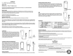
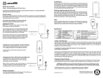
H.M.I. (Human-Machine Interface) Configuration:
No
Item
No
Item
1 Master switch// LED : Power On/Off
9
2 PV I/P -1: DC sockets for 5.0x2.1mm plug ; 8A
10 AC O/P sockets: Pure Sine Wave
3 PV I/P-2 : terminal block for 25AMax (total)
11 USB DC O/P socket: 5VDC
4 AC I/P// LED :100V~240Vac/ 50~60Hz
12 Battery Storage Display Switch
5 Charge status LED : Charge status of system
13 Battery Storage LED Display
6 DC O/P Switch //LED
14 Carrying handle
7 Car cigarette O/P socket: 12VDC of battery
15 Trolley and Brake
8 DC O/P socket: 24V/70W
AC O/P Switch//LED
Equipment Introduction:
1. Logic Chart for Solar Power Box and PV Panel
2. Main Components:
2.1. The solar power panel applies to 12VDC energy storage battery system.
2.2. PV charge/discharge controller owns 12VDC/25A input and 12V/30A output.
2.3. Built-in constant current VAC/VDC & C.C Mode AC/DC power supply unit.
2.4. BMS Battery (LiFePO4 battery management system).
2.5. LiFePO4 battery (of 4 cells in serial connection with 12.8V.DC nominal volts).
2.6. DC/AC inverter and 5VDC-DC USB port.
2.7. DC/DC converter.
2.8. The LED display of battery storage shows the voltage as power energy of battery.
Specifications:
Item
Condition
Value
Unit
Input
Solar Panel Terminal block(total)
80Wp(default option), Vmp<23V;Imp=25A
20~ 360
Wp
Input Power DC plug (each)
80Wp(default option) Imp<8A, Vmp<24V
20~120
Wp
AC power socket
AC100~240V//50~60Hz
100~240
Vac
Ratings for solar charge controller
I/P:12V/25A max; O/P:12V/30A max
12
VDC
12.8V/20Ah // 30Ah // 40Ah (default )
20//30//40
Ah
W
Energy storage battery
LiFePO4 battery (3 options)
AC Output
AC output power
300W/600VA, 220V//110V/50/60Hz
300
Output wave
Pure Sine Wave
YES
Efficiency
≧85%
85%
Overload / Short circuit protection
Circuit control with self-recovery fuse
YES
Overload ability
100%≦Load≦500% for 3S; 500%≦Load 1S
3
S
%
DC Output
DC
Cigarette lighter socket
9.6VDC~14.60VDC/6A max
12
VDC
output
DC plug
24VDC/3Amax (customized)
24V/3A
VDC/A
USB port
5V500mA
5/500
V/mA
Working Temperature
-20~75
℃
Ambient Temperature
-30~55
℃
Others
Storage Temperature
Battery<35℃ recommended
45
℃
Weight (kg)
13 kgs (with battery of 12V x 40Ah)
13
Kg
Noise (1M)
<45dB
45
dB
Output Outlet Configuration
Vac Universal output socket × 2
USB Port ×1 VDC cigarette lighter socket ×1
VDC output plug x1
Relative Humidity
5~90% ,W/O Moisture
Dimension
380 x 220 x 260
Altitude
under 3000M
mm
3000
Feature:
1. Application to PV panel from 20w to 360w, but the input current is limited at 25A max.
2. BMS auto protects the panel & battery from over-charging & over-discharging, short-circuit, low voltage,
overheating, reverse connection, inrush voltage and over-load.
3. Hybrid input power source: AC Source and Solar Power Source.
4. Working as power supply system, DC/AC UPS or a secondary battery.
5. Equipped with battery LiFePO4 and built-in protection system.
6. The device can meanwhile be working on charging and discharging mode.
7. Auto detects the storage of battery, if the power energy of battery is under low level; the LED light will
flash continually.
8. The device owns high efficiency on charging mode.
9. PV Power Box sets the multi-port terminal blocks with a parallel connection.
Caution:
1. If assembling, please note that the red Y-type terminal of PV panel connects up the anode (+) and the
black or blue terminal block connects up the cathode (-) of solar power box.
2. Turns off the electric power before cleaning the device; please clean by dry cloth only.
3. Please check the LED display of battery storage before using, if it is low power level, please recharge.
4. Please turn off the electric power if un-using, it can be avoided the battery power to flow away.
M
5. Turns on the electric power without a load, please note that the high voltage still runs on AC outlet.
6. Please avoid the environment of high temperature when the battery is using.
7. Do not un-screw the solar power box except the qualified engineer.
8. To avoid the water or anything into the device.
9. Do not connect with additional battery to extend the power of device.
10. If user meets out of right operation or other operating problems, please turn off the electric power.
11. If the device is frequently extended on limit-use, it will reduce the product life.
How to Use:
1. Charging:
1.1. AC I/P as an Auxiliary Power Source
1.1.1. Turns on master switch (On/Off switch).
1.1.2. Connects up the electric power.
1.1.3. If the power energy of battery is on charge completion, the LED light will be constant light otherwise
it will be flashing continually.
1.2 Solar Power Source DC I/P
1.2.1. Turns on master switch (On/Off switch).
1.2.2. Y-type terminals of PV panel connects up the terminal block of Solar Power Box and also check if
everything is right for the red cable terminal to the positive (+) and the black or blue cable terminal to the
negative (-) of the terminal blocks on the solar power box.
1.2.3. In using the DC plug, user should connect the male DC cable of PV panel with the female DC socket.
1.2.4. If the power energy of battery is on charge completion, the LED light will be constant light otherwise
it will be flashing continually.
2. The Status of Battery Storage:
In main quiescent mode, user turns on the spring switch of battery that will know the power status via LED
display in charging mode (SoC) and will also know how voltage the battery storage in its occupation is. In
dynamic mode, user should pay attention to the operating temperature of battery in discharge current so as
to avoid affecting the battery energy storage directly. The following table is made according to the charge
voltage (SoC) and storage of battery.
Battery Storage
0%~15%
15%~35%
35%~55%
55%~75%
75%~100%
Voltage Level
9.6V~
12.2V~
12.6V~
12.8V~
13.2V~
Efficient load
DC
DC
AC/DC
AC/DC
AC/DC
Green LEDs
No
No
1~2
2~3
4~5
Orange LEDs
No
1~3
Red
1~2
LEDs
2.1. High Power Storage Battery
If the LED indicates green light, the power of battery shows in full level and the voltage is above 12.6V
usually.
2.2. Low Power Storage Battery
If the LED indicates yellow light, the battery power shows in low level, then user can choose the DC
output; the battery could be used for some time.
2.3. Protection for Low Voltage
If the red LED light is flashing, the Under-Voltage-Protection (UVP) will be working at once. When the
UVP is working, the protection system will reject any operation and auto checks up the status of battery
storage. At this stage, if the voltage is under 9.6V, the LED display will auto shut off.
3. Discharging:
The most output is 360W including AC/DC discharging at the same time. If the master switch is
turned on, the device will be ready for operation; user should pay attention to the status of battery power.
3.1. AC Discharge (300W/600VA)
In using AC output, please turn on the AC power switch. User should care about the input ratings of load
& also check what the voltage is (110VAC or 220VAC). Note: 5VDC USB socket is set up at this unit
with a rating of 5VDC/500m A.
3.2. DC Discharge (Constant DC output socket & Car cigarette output socket is 12VDC/6A)
In using DC output, please turn on the DC power switch. User should care about the input ratings of load
& check if the DC rating is less than the power consumption. Please refer to the DC outlet rating as
specification.
Trouble Shooting:
1. If AC load cannot keep working, please check up the solar power bank according to the following
procedures:
1.1. Please check if the rated power of the load is <300W ?
1.2. If the rate is the same as <300W condition, please check whether the voltage of battery storage has
got a “Duty Cycle”. Usually High Electric Potential will drive the AC load, but if an AC load gets higher
wattage, it will absorb higher current draw and also work continually, the UVP will be started to protect the
system and auto shut down. In this case, please check whether DC outlet is working normally, if so, please
re-charge the battery.
1.3. If the LED display of battery storage shows the status of full or normal power however the AC output
cannot work, the UVP will be started due to the single cell volt may be dropped to 2.4V.
If the single cell gets such problem, it could be aging, we suggest that you should change into new battery
or send it back for investigation.
2. Instantaneous over-load
The total output of solar power bank is 300W with two AC output sockets. If the two AC outputs gets the
value of loads which are more than 150 watts meanwhile, the protection system will auto-cutoff the electric
power to protect the inverter. The solution is to run 1st load first and again run 2nd load.
3. The LED display of battery storage to be flickering by heavy load
When it is full load, the high current will be output & the voltage will be quickly declined. The power light
will be rapidly decreased to reflect on the charge sheet until the low pressure protection (UVP) to be started
and auto-cutoff the electric power, this event is regarded dynamic "Floating Voltage".
Another condition, if there is one or two green lights that still indicates with considerable power and gets
overload, it will be happened as above statement. The best solution is to re-charge the battery up to full
power.
4. Both voltage rating and device do not match up
If the device cannot work or be burnt, the problem is that both nominal voltages cannot match up. Please
recheck the specification of power supply unit and solar power bank.
5. Reduction of working wattage hour under different discharge current
In the same condition for batteries, the voltage maybe offer different power energy and discharge current,
this is the electrochemical characteristic of a battery. Therefore, the solar power box should use under 0.5
discharge current (0.5 Ca) of battery capacity.
6. Overheat protection
Auto- cutoff for overheating (up to 75℃). Please refer to the specifications.
7. How to keep high voltage in free
If the battery is un-used, please keep the voltage of battery about 60% and charge/discharge once for 3
months each.
8. How to restart the system after over-current protection.
Usually there is electronic protection for over-current or short-circuit at each input/output port. If an
overload or short circuit be happened at any port, it must be removed before the system has returned to
work.