1
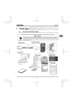
Product User Manual
iSTAR
and enterprise branch and head offices
CP-12055-M
www.enochsystems.com
1-877-722-1116
[email protected]
Copyright © 2013 Enoch Systems, LLC, Enoch Systems and the Enoch Systems logo are trademarks or registered trademarks of Enoch Systems, LLC and/or its affiliates in the U.S. and other countries.
Third-party trademarks mentioned are the property of their respective owners. All rights reserved.
DUNDANT
REDUNDANT POWER SUPPLY
CP-12055
727 Phillips Drive City of Industry, CA 91748
1. General
This specification describes the physical, functional and electrical Characteristics
of a redundancy 550+550 watts. 5-output, fan-cooled switching power supplies.
1.1
Parameter Specification
Unless specification otherwise, all parameters must be meet over the limits of
temperature, load and input voltage.
2. Input Characteristics
2.1
Input Voltage:
90Vac To 264Vac,With Active Power Factor ,PF=90% Min.
2.2
Input Waveform
The unit is capable of operating with 10% distorted sine wave input. It is
measured by a distortion analyzer. Its flat-topping clipped 10% from the peak
value of standard sine-wave.
2.3
Input Frequency
47 – 63Hz
2.4
Input current
4.5AΰRMSαFOR 230VAC/9AΰRMSαFOR 115VAC
2.5
In-Rush Current
CONDITION
2.6
LIMITS
132/264Vac, Full load.
No damage shall occur or
Turn off 1 sec; turn on at
components over stressed,
peak of input voltage cycle.
25к Air Ambient cold start.
Input Fuse shall not blow.
Line Regulation
CONDTION
LIMITS
Full Load 90Vac To 264Vac,
With Active Power Factor ,PF=90% Min.
1%
2.7
Input Leakage Current
Input leakage current from line to frame ground will be less than 3.5mA rms. for
each power module. Condition: 264Vac/60Hz
2.8
Dielectric Withstand Voltage
Primary to Secondary : 1500V ac / 50Hz for 1 Minute.
Primary to Safety Ground: 1500V ac / 50Hz for 1 Minute.
2.9
Insulation Resistance
Primary to Safety Ground : 500Vdc, 50Mohms Minimum.
3. Output Characteristics
3.1
DC Output Characteristics
To be met under all combinations of loading.
Output Voltageʳ
Output
Current
Min.ʳ
Output
Current
Max.ʳ
+5V
+12V
-5V
-12V
+3.3V
+5VSB
1.0A
2.0A
0A
0A
1.0A
0.1A
30Amax
42Amax
0.5Amax
0.5Amax
25Amax
3Amax
Output
Current
Peakʳ
Regulation
Loadʳ
Regulation
Line
Output
Ripple &
Noise
Max.[P-P]
± 5%
± 5%
± 10%
± 10%
± 5%
± 5%
± 1%
± 1%
± 1%
± 1%
± 1%
± 1%
50mV
120mV
50mV
120mV
50mV
50mV
Note1: Noise bandwidth is from DC to 20MHz. Add 0.1uF/10uF Capacitor at
output connector terminals for Ripple And Noise measurement.
Note2: Regulation tolerance shall include temperature change, warm up drift
and dynamic load.
Note3: Combined Total Power from +3.3V and +5V Rails Shall Not Exceed 150W
Note4: The Total Output Power Shall Not exceeds 550W.
3.2
Overshoot
Any output overshoots at TURN-ON shall not exceed 10% (+5V/+12V output) and
10% (-12V/ output) of nominal voltage value.
3.3
Efficiency
70% min. at full load test.
4. Time Sequence
4.1
Hold-Up Time
Unit shall continue to supply regulated DC outputs and power good signal for at
least 16 Milliseconds at 115/230Vac full load after a loss of AC input voltage
which shall be represented by a short circuit at the AC input.
4.2
Power Good Signal
The power supply shall provide a power-good signal to indicate proper operation
of the power supply. This signal shall be a TTL compatible high level for normal
operation; low level for fault conditions.
4.2.1
Fan out
Power Good output circuit shall consist of an active pull down component and
a passive pull up resistor.
Power-Good output voltage to be met under recommended loading conditions.
CONDITION
LIMITS
I OH=-140uA Min.
VOH=2.7V Min.
I OL=2.8mA Min.
VOL=0.4V Min.
4.3
+5V Volt and Power Good Output Rise Time
4.3.1
+ 5 Volt Output Rise Time
The +5V output shall have a turn-on rise time of less than 100ms under all
load conditions. Rise time is measured between 0.0 and 4.75V.
The +5V output shall not vary from a smooth curve by more than 0.5Vp-p during
turn-on and turn-off.
4.3.2. Power Good Output Rise
+4.75V
+4.75V
Ts ->
+5V Output
Power Good Signal
<- Tr -> <- Td
->
->
T1 <-
Note: Tr d 100 ms, T1 t 1 ms, Td = 100 - 500 ms.
4.4
Start-Up timing
All output shall be stable and in regulation in less than 2.0 second under all
load and line condition. Start-up time is measured between the AC turn-on and
11.40V on +12V
4.5
Dynamic Load Response Time
Transient response is measured by switching the output load from 80 to 100 to
80 percent of its full value at a frequency of 100Hz and 50% duty cycle, step
load change is 0.5A/us, The magnitude Vr is less than +/-5% of +5V and +12V
output, the recovery time Tr is less than 1mS.
5. Protection
5.1
Over Power Protection
This power supply shut down all DC output when outputs are overloaded to
the limit. The power supply logic shall latch into the off state requiring a
power on cycle to be performed by the operator. The power supply will turnoff within 20ms of the occurrence of the overload.
CONDITION
Nominal input
5.2
LIMITS
When output power is over to 120% ~ 150%
Over Voltage Protection
The power supply shall latch off if the +5VDC or +12VDC or +3.3VDC maximum
voltage exceeds the limits shown. The AC must be recycled to restart.
5.2.1
+ 5VDC
CONDITION
All operating
5.2.2
All operating
LIMITS
+3.7V-4.7Vdc
+12VDC
CONDITION
All operating
5.3
+5.7V-6.7Vdc
+3.3VDC
CONDITION
5.2.3
LIMITS
LIMITS
+Max.13.0V-15.0Vdc
Short Circuit Protection
short circuit placed on +3.3V/+5V/+12V/-12V output shall cause no damage to this
unit.The power supply shall be shut down.
AUTO-RECOVERED: 5VSB,
5.4
No Load Operation
When primary power is applied, with no load on any output voltage, no damage
or hazardous condition shall occur. In such a case, the power supply shall
power up and stabilize.
6. System Interface Signal
6.1
Power System Fault Signal
The Hot-Swap Redundant Power Supply shall give fault signal (an open
collector) that will indicate the status of the power supply operation.
If one of the power supply unit shut down, the power fault signal could be
generated. This signal shall be high level for normal operation; Low level for
fault conditions.
6.2
Alarm Beeping Sound
The alarm system monitors the power supply failure and provides alarm to
indicate the status of the power supply. By checking the LED on the power
supply, end users will be able to locate the defective power unit. The alarm
system will give a beeping sound to indicate the power supply failure until
that particular power unit is replaced.
Beeping sound could be suspended before the failure power supply unit replaced.
7. Physical Characteristics
7.1
Size
See Figure1
7.2
Mounting Requirements
See Figure1
7.3
Cooling
BY BALL-BEARING FAN.
8. Connections
8.1
DC Output Wire List
Connector
P1-1
P1-1-1
P1-2
P1-3
P1-3-1
P1-4
P1-4-1
P1-5
P1-6
P1-7
P1-8
P1-9
P1-10
P1-10-1
P1-11
P1-12
Output
ATX24P
+3.3V
+3.3V Sense
+3.3V
COM
COM Sense
+5V
+5V Sense
COM
+5V
COM
PWR OK
+5VSB
+12V
+12V Sense
+12V
+3.3V
Wire Color
Orange
Orange
Orange
Black
Black
Red
Red
Black
Red
Black
Gray
Purple
Yellow
Yellow
Yellow
Orange
Wire Size
18 AWG
22 AWG
16 AWG
18 AWG
22 AWG
18 AWG
22 AWG
16 AWG
16 AWG
16 AWG
18 AWG
16 AWG
18 AWG
22 AWG
16 AWG
16 AWG
P1-13
P1-14
P1-15
P1-16
P1-17
P1-18
P1-19
P1-20
P1-21
P1-22
P1-23
+3.3V
-12V
COM
PS-ON
COM
COM
COM
Reserved(-5V in TAX)
+5V
+5V
+5V
Orange
Blue
Black
Green
Black
Black
Black
N.C
Red
Red
Red
16 AWG
16 AWG
16 AWG
16 AWG
16 AWG
16 AWG
16 AWG
P1-24
COM
Black
16 AWG
Connector
1
2
3
4
Output
+12V
COM
COM
+5V
4P peripheral
Wire Color
Yellow
Black
Black
Red
Wire Size
18 AWG
18 AWG
18 AWG
18 AWG
Connector
1
2
3
4
Output
COM
COM
+12V
+12V
CPU 4p
Wire Color
Black
Black
Yellow
Yellow
Wire Size
18 AWG
18 AWG
18 AWG
18 AWG
Connector
1
2
3
4
5
6
7
8
Output
COM
COM
COM
COM
+12V
+12V
+12V
+12V
CPU 8p
Wire Color
Black
Black
Black
Black
Yellow
Yellow
Yellow
Yellow
Wire Size
18 AWG
18 AWG
18 AWG
18 AWG
18 AWG
18 AWG
18 AWG
18 AWG
16 AWG
18 AWG
16 AWG
Connector
1
2
3
4
5
6
Output
COM
COM
COM
+12V
+12V
+12V
PCI Express
Wire Color
Black
Black
Black
Yellow
Yellow
Yellow
Wire Size
18 AWG
18 AWG
18 AWG
18 AWG
18 AWG
18 AWG
Connector
1
2
3
4
5
Output
+3.3V
COM
+5V
GND
+12V
SATA
Wire Color
Orange
Black
Red
Black
Yellow
Wire Size
18 AWG
18 AWG
18 AWG
18 AWG
18 AWG
PS LED Connector
Output GREEN LED
Wire Color Wire Size
GREEN
22 AWG
BLACK
22 AWG
TTL
Output
Wire Color Wire Size
BLUE
22 AWG
BLACK
22 AWG
8.2
Connector
AC Input
IEC-320 power inlet.
(Optional)
9. Environmental
9.1
Temperature
9.1.1
Operating
50 to 122л (10 to 40к). De-rate Linearly to 50% at 70к
9.1.2
Non-Operating
-4.0 to 140л (-20 to 60к)
9.2
Relative Humidity
9.2.1
Operating
20 to 90 % non-condensing at 104л (40к).
9.2.2
Non-Operating
10 to 90 % non-condensing at 104л (40к)
9.3
Altitude
9.3.1
Operating
Sea level to 10,000feet.
9.3.2
Non-Operating
Sea Level to 40,000 feet.
9.4
Shock
9.4.1
Operating
The power supply shall exhibit no sings of damage or degradation of
performances when subjected to a shock of 5g’s for 11 ms, with 1 1/2 sine
wave for each of the perpendicular axes X,Y and Z.
9.4.2
Non-Operating
The power supply shall exhibit no sings of damage or degradation of
performances when subjected to a shock of 30g’s for 11 ms, with 1 1/2
sine-wave for each of the perpendicular axes X, Y and Z.
9.5
Vibration
9.5.1
Operating
The power supply shall be subjected to a vibration test consisting of a 10
to 500Hz sweep at a constant acceleration of 0.5g for a duration of one (1)
Hour for each of the perpendicular axes X, Y and Z.
The output voltage shall remain within specification.
9.5.2
Non-Operating
The power supply shall be subjected to a vibration test consisting of a 10
to 300Hz sweep at a constant acceleration of 2.0g for a duration of one (1)
hour for each of the perpendicular axes X, Y and Z.
The power supply shall not incur physical damage or degradation of any
characteristics below the performance specifications.
9.6
Power Line Transient
9.6.1
Drop out
With a full cycle input voltage drop-out at 50 Hz, the power supply shall
operating within the prescribed voltages whit a drop-out cycle repetition rate
of 500ms.
CONDITIONS
Full load, Nom. AC voltage Input
9.6.2
LIMITS
Meet all requirements
Transient Voltage Spikes
The unit shall meet the following standards, The IEEE Standard 587-1980 for
surge withstand capability under categories A and B. The crest value of the
first half peak of the injected Ring-wave (0.5/10us) Bi-wave (1.2/50us) will be
3k volts open circuit and 3KA (8us X 20us) short circuit.
IEC 801–2 (ESD) to a level of 8KV contact, and 15K air discharge without
causing the device(s) to fail the test.
IEC 801-4 (EFT) on the power lines and all I/O cables to a level of 2.5KV
Without causing the Device(s) to fail the test.
IEC 801-5 Surge immunity measurement on the input power source of 2.5KV.
All output shall be stable and in regulation.
9.7
Acoustic Noise
10. Regulatory Agency Certification
10.1
RFI/EMI Standards
The power supply, When installed in system, shall comply with the following
Radiated and conducted emissions standards:
(1) FCC part 15, Subpart B, Class B computing device.
(2) CISPR22 (EN55022) Class B.
(3) VCCI Class 2.
These limits shall be met with a margin of at less 6dB at all applicable
frequencies. The units shall comply with the above limits when tested under all
normal working conditions and with all interface cables connected.
10.2
Safety Standard
The power supply shall be certified with the following safety standards,
(1) UL 60950-1 (Information Processing / Business equipment).
(2) c-UL
(3) TUV Certification to EN60950-1
(4) CE Certificate & Test Report.
(5) Harmonic Requirement ---IEC61000-3-2 & IEC61000-3-3
Class “ D “.
11. Reliability
11.1
Mean Time Between Failure(MTBF)
Using MIL 217E the calculated MTBF=100,000 hours at 25к 75% loading.
11.2
Warranty
Two (2) years manufacture’s warranty.
05/10'08
1:1
DQ.23166
PRA500 MV
1of1
A0
05/10'08
1:1
DQ.23166
PRA500 MV
A0
1of1