1
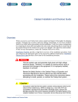
System Monitor/Controller
SMC Troubleshooting
Page 1 of 33
SMC Troubleshooting
In general, use the maintenance software for troubleshooting the FLEX system monitor/controller (SMC). Refer to Maintenance Software.
Cables
Calibration
Computer
Cooling
DIB Interface
Field Replaceable Units
Instruments
Maintenance Software
Manipulator
Power
Preventive Maintenance
Safety
SMC
Support Board
Support Cabinet
Test Head
Troubleshooting
Training
Product Integration Manuals
Site Prep Guide
Install & Checkout Guide
HOME
HELP
If further troubleshooting is required, or if the maintenance software is not functioning,
use the SMC flowchart to troubleshoot SMC assembly failures. This topic consists of
the following sections:
• Checking the System
• Using the SMC Assembly Checks and Flowchart
Note
In addition to using the SMC flowchart for troubleshooting SMC assembly faults,
use the flowchart after a fault has been corrected to verify that there are no other
SMC assembly faults in the system.
When performing further troubleshooting, you can also refer to specific pinouts and
wiring and signals information.
Checking the System
Test your system before you use the troubleshooting procedures that are specific to
the SMC assembly.
Verify that the FLEX continuity check passes. Refer to Maintenance Software. Resolve any failures before continuing.
Rev. 0406
System Monitor/Controller
SMC Troubleshooting
Page 2 of 33
Using the SMC Assembly Checks and Flowchart
Use the SMC assembly checks and flowchart to troubleshoot the SMC assembly as
follows:
Cables
Calibration
Computer
Cooling
DIB Interface
Field Replaceable Units
Instruments
Maintenance Software
Manipulator
Power
Preventive Maintenance
Safety
SMC
Support Board
Support Cabinet
Test Head
Troubleshooting
Training
Product Integration Manuals
Site Prep Guide
Install & Checkout Guide
HOME
HELP
1. Run the quick or full SMC assembly checks.
2. If a check fails, follow the SMC assembly flowchart to determine the cause of the failure.
3. Replace the board or other appropriate hardware.
4. Run the checks again.
5. Run the FLEX continuity check.
Rev. 0406
System Monitor/Controller
SMC Troubleshooting
Page 3 of 33
SMC Troubleshooting Introduction
The SMC subsystem controls and monitors the system operations. The SMC subsystem includes a set of standard nodes located on each instrument board.
Cables
Calibration
Computer
Cooling
DIB Interface
Field Replaceable Units
Instruments
Maintenance Software
Manipulator
Power
Preventive Maintenance
Safety
SMC
Support Board
Support Cabinet
Test Head
Troubleshooting
Training
Product Integration Manuals
Site Prep Guide
Install & Checkout Guide
HOME
HELP
The SMC assembly shown in the figure SMC Assembly, uses the local operating network (LON) nodes to monitor and control system functions. Each LON node reports to
the SMC assembly. The SMC system node processes the information the SMC assembly receives. The system node instructs the SMC assembly to take control of the
entire system when necessary. Under certain circumstances, the system node directs
the SMC to shut down test power, system power, or to display a warning to the operator. Before replacing the SMC assembly, it is necessary to review any information
logged in the software maintenance window and in the system log file.
LON Bus
Interface
Ethernet
Interface
386EX SingleBoard Computer
Support Cabinet
Node (Main Board)
System
Node
SMC Assembly
Rev. 0406
System Monitor/Controller
Cables
Calibration
Computer
Cooling
DIB Interface
Field Replaceable Units
Instruments
Maintenance Software
Manipulator
Power
Preventive Maintenance
Safety
SMC
Support Board
Support Cabinet
Test Head
Troubleshooting
Training
Product Integration Manuals
Site Prep Guide
Install & Checkout Guide
HOME
HELP
SMC Troubleshooting
Page 4 of 33
SMC related faults are usually symptoms of other failures. For example, a failing power board on an instrument may generate an F2 fault via the SMC subsystem. The fault
results in the SMC assembly shutting down test power. The operator may believe the
SMC assembly is causing the power-down. However, the SMC assembly is just a
symptom of the fault and not the cause of the fault. So, before troubleshooting for an
SMC problem, it is recommended to rule out other components and field replaceable
units first.
The SMC troubleshooting section is divided into two parts to reflect the distinction between faults seen and acted on by the SMC and faults that are internal to the SMC
subsystem. A common problem is determining whether to troubleshoot with the SMC
or troubleshoot the SMC. Operators should attempt to troubleshoot with the SMC first.
• Troubleshooting with the SMC
• Troubleshooting the SMC
Rev. 0406
System Monitor/Controller
SMC Troubleshooting
Page 5 of 33
Troubleshooting with the SMC
Overview
The first step in troubleshooting an SMC problem is to distinguish between SMC observed faults and SMC-induced problems. This section provides procedures and flowcharts to troubleshoot SMC-monitored faults.
Cables
Calibration
Computer
Cooling
DIB Interface
Field Replaceable Units
Instruments
Maintenance Software
Manipulator
Power
Preventive Maintenance
Safety
SMC
Support Board
Support Cabinet
Test Head
Troubleshooting
Training
Product Integration Manuals
Site Prep Guide
Install & Checkout Guide
HOME
HELP
Generic Node Monitors
Each instrument board is equipped with an SMC node. This node is mounted on a rider
card that resides on the power board section of each instrument. The node consists of
a small multiplexer, a calibrated analog-to-digital (A/D) converter, a control microprocessor, and communications circuits. The node contains standard self-monitoring circuitry and it is customized for each instrument type. Each instrument may route
parameters that are of interest to the node for monitoring. These parameters differ between instrument types.
The node also acts as a power-on sequence controller for each instrument. The power
sequence and monitor levels are stored in a programmable table on the node and on
the test computer. Saving tables on the test computer eliminates the need to upload a
full copy of an instrument's table every time test power is cycled. The functional software (communications and conversion routines) for the node also resides on the node.
See the table Standard Set of Node Monitors.
Rev. 0406
System Monitor/Controller
SMC Troubleshooting
Page 6 of 33
Standard Set of Node Monitors
Cables
Calibration
Computer
Cooling
DIB Interface
Field Replaceable Units
Instruments
Maintenance Software
Manipulator
Power
Preventive Maintenance
Safety
SMC
Support Board
Support Cabinet
Test Head
Troubleshooting
Training
Product Integration Manuals
Site Prep Guide
Install & Checkout Guide
HOME
HELP
Monitor
Code
Description
Local_M5V
-5V SMC node power. Provides operating power to the node from the SMC main board.
Local_P5V
+5V SMC node power. Provides operating power to the node from the SMC main board.
M10V_MON
Derived from Local_M5V and Local_P5V used by node
P10V_MON
Derived from Local_M5V and Local_P5V used by node
200MV_REF
200 mV reference that the A/D converter uses on the node.
2.5V_REF
2.5V reference that the A/D converter uses on the node.
1.25V_REF
1.25V reference that the A/D converter uses on the node.
Support Cabinet Node Monitors
The support cabinet node (SCN, part of the SMC assembly) monitors SMC power,
central power to all nodes, power to the clock module, main blower rotation, and PDU
functions. The SCN monitors can be viewed at the SMC tab of the maintenance window. See the table Support Cabinet Node Monitors and the figure SMC Monitor Window in the Maintenance Window.
The SCN resides on the SMC assembly but is not a field replaceable unit. See the figure SMC Assembly. Failure of the SCN requires replacement of the SMC assembly.
The SCN also contains the standard set of node monitors. See the table Standard Set
of Node Monitors.
Rev. 0406
System Monitor/Controller
SMC Troubleshooting
Page 7 of 33
Support Cabinet Node Monitors
Monitor Name
Cables
Calibration
Computer
Cooling
DIB Interface
Field Replaceable Units
Instruments
Maintenance Software
Manipulator
Power
Preventive Maintenance
Safety
SMC
Support Board
Support Cabinet
Test Head
Troubleshooting
Training
Product Integration Manuals
Site Prep Guide
Install & Checkout Guide
HOME
HELP
Description
LA703_ P12
+12V to clock
SMCTH_P5V
+5V to all nodes
P5V_TH_Ise
Current sense for +5V node power
SMCTH_M5V
-5V to all nodes
P5V_SC_Ise
Current sense for +5V support cabinet power
LA703_ P5
+5V to clock
LA703_M15
-15V to clock
LA703_M5
-5V to clock
SMC_M5V
Support cabinet -5V
SMC_P5V
Support cabinet +5V
24V_P_GOOD
3.3V_FPGA
SWPS1 +24V
SMC 3.3V
BLOWER
Speed of main system blower
PDU_V0
PDU AC voltage, phase 1
PDU_I1
Current drawn on 48V connector 1
PDU_I2
Current drawn on 48V connector 2
PDU_V1
PDU AC voltage, phase 2
PDU_V2
PDU AC voltage, phase 3
PDU_VAB
PDU input voltage, phase 1
PDU_VAC
PDU input voltage, phase 2
PDU_VBC
PDU input voltage, phase 3
Rev. 0406
System Monitor/Controller
Cables
Calibration
Computer
Cooling
DIB Interface
Field Replaceable Units
Instruments
Maintenance Software
Manipulator
Power
Preventive Maintenance
Safety
SMC
Support Board
Support Cabinet
Test Head
Troubleshooting
Training
Product Integration Manuals
Site Prep Guide
Install & Checkout Guide
HOME
HELP
SMC Troubleshooting
Page 8 of 33
SMC Monitor Window in the Maintenance Window
Support Board Monitors
The master support board (MSB) monitors the 48V system power that the PDU produces at the test head. The board also is the communications point for the boards-in
signal chain. The boards-in chain is a physical series loop that passes through each
instrument and filler card as well as the test head door interlock switch. All instruments
and filler cards must be inserted in their slots and the test head door must be closed,
or the test head door interlock switch monitor will signal a failure.
Rev. 0406
System Monitor/Controller
SMC Troubleshooting
Page 9 of 33
OVERVIEW
Cables
Calibration
Computer
Cooling
DIB Interface
Field Replaceable Units
Instruments
Maintenance Software
Manipulator
Power
Preventive Maintenance
Safety
SMC
Support Board
Support Cabinet
Test Head
Troubleshooting
Training
Product Integration Manuals
Site Prep Guide
Install & Checkout Guide
HOME
HELP
The MSB monitors the boards-installed loop known as BOARDS_INS. This serial signal chain loops from the MSB SMC node through the backplane and all of the instruments in the system and through the micro-switch located on the test head door. See
the figure Signal Block Diagram. The purpose of the loop is to prevent operation in the
event that any instruments or filler cards are not installed in the test head slots or if the
test head door is left open. Because leaving a slot empty or opening the test head door
disrupts the cooling air flow. This disruption may be severe enough to cause instrument failures or shorten components expected life due to overheating.
TROUBLESHOOTING GUIDE
Failure of the boards-installed loop results in a system shutdown by the SMC. Examination of the tester status file or the SMC status window will reveal a fault on the
BRDS_INST line of the MSB in slot seven. The value will be greater than 1.7V (approximately) if the loop is open and less than 1.7V (approximately) if it is closed. The most
common cause of failures are an open test head door or failure to install a filler card
when an instrument is removed. Before troubleshooting, do a visual examination and
try to understand the activities that preceded the shut down. Replace any instruments
or filled boards that were removed prior to the shutdown. Examine the door and interlock switch for proper operation. Continuity checks can be performed on each instrument and filler card. The entire loop may be evaluated by removing the test interface
plate to obtain access to the backplane and conducting continuity checks with the interface removed. Refer to the Boards Installed Flowchart for troubleshooting.
Rev. 0406
System Monitor/Controller
SMC Troubleshooting
Page 10 of 33
BACKPLANE
SLOTS 8-13
11f
Cables
Calibration
Computer
Cooling
DIB Interface
Field Replaceable Units
Instruments
Maintenance Software
Manipulator
Power
Preventive Maintenance
Safety
SMC
Support Board
Support Cabinet
Test Head
Troubleshooting
Training
Product Integration Manuals
Site Prep Guide
Install & Checkout Guide
11a
MASTER SB
100h
100a
SLOTS 1-6
11f
11a
4f
3A
4e
3B
J27
SMC
SLOT 7
P1
P4
LON
LON to SMC Main
Board via J27 and
866-162-00
2
1
2
1
P3
Pin 2
11a
11f
SLOTS 14-19
100a
100h
SLAVE SB
11a
11f
SLOTS 21-26
Door Interlock Switch
(Normally Open)
NOTE: Slot ranges indicate multiple boards.
Pin numbers are the same on each board.
Signal Block Diagram
HOME
HELP
Rev. 0406
System Monitor/Controller
SMC Troubleshooting
Page 11 of 33
The SMC shuts down the
system due to
BRDS_INSTA fault
Cables
Calibration
Computer
Cooling
DIB Interface
Field Replaceable Units
Instruments
Maintenance Software
Manipulator
Power
Preventive Maintenance
Safety
SMC
Support Board
Support Cabinet
Test Head
Troubleshooting
Training
Product Integration Manuals
Site Prep Guide
Install & Checkout Guide
Does door
switch and wiring
pass continuity
test?
Is the
test head door
closed?
NO
Close the test
head door.
YES
Retest
Are
all instrument
and filler boards
installed?
Install all
instrument and
filler boards
YES
NO
NO
Repair or replace
door interlock
switch and/or
wiring
NO
Replace
defective
instrument or
filler board
YES
Perform
continuity checks
on each board.
Do all boards pass
continuity checks?
Retest
YES
Verfiy operation of door
switch with an ohmmeter.
Replace master
support board
Boards Installed Flowchart
HOME
HELP
Rev. 0406
System Monitor/Controller
SMC Troubleshooting
Page 12 of 33
Note
The primary purpose of the test head interlock switch is to disable test system
power if the test head door is opened during operation. Opening the test head door
reduces the effectiveness of the cooling system. The interlock switch is monitored
by the SMC which interrupts test power when the switch is activated. This switch is
not designed as an electrical safety feature.
Cables
Calibration
Computer
Cooling
DIB Interface
Field Replaceable Units
Instruments
Maintenance Software
Manipulator
Power
Preventive Maintenance
Safety
SMC
Support Board
Support Cabinet
Test Head
Troubleshooting
Training
Product Integration Manuals
Site Prep Guide
Install & Checkout Guide
Additional monitor points are the digital signal processor (DSP) and Picoclock power
supplies and presence indicators. Refer to the table Support Board Monitors for descriptions of the support board monitors. The table shows the master support board
monitors, the slave support board monitors are a subset (there are no P48V_IN or
BRDS_INSTA monitors). The monitors can be viewed in the maintenance window by
selecting the SMC tab. See the figure Support Board Monitor Window in the Maintenance Window.
Support Board Monitors
Instrument Monitors
P48V_IN
P3.3V_MAIND
P5V_Shared
DSP1_PRESE
Description
Main 48 VDC power to instrument from the PDU.
3.3 VDC instrument power derived from the 48V mains by the power converters on the support
board power section.
Support board +5V
DSP module present signals.
DSP3_PRESE
DSP3_PRESE
DSP4_PRESE
HOME
HELP
Rev. 0406
System Monitor/Controller
SMC Troubleshooting
Page 13 of 33
Support Board Monitors (Continued)
Instrument Monitors
DSP1_S_1.8
Description
DSP supply
DSP2_S_1.8
Cables
Calibration
Computer
Cooling
DIB Interface
Field Replaceable Units
Instruments
Maintenance Software
Manipulator
Power
Preventive Maintenance
Safety
SMC
Support Board
Support Cabinet
Test Head
Troubleshooting
Training
Product Integration Manuals
Site Prep Guide
Install & Checkout Guide
DSP3_S_1.8
DSP4_S_1.8
DSP1_S_2.5
DSP2_S_2.5
DSP3_S_2.5
DSP4_S_2.5
P_15_UVP_DC
M15_UVP_DC
Monitors the overvoltage and undervoltage protection feedback voltage of the ±15V and ±75V
converters on the support board power section. These signals will appear out of range if the
converter is being steered due to an undervoltage or overvoltage condition.
P75_UVP_DC
M75_UVP_DC
P_15_OVP_DC
M15_OVP_DC
P75_OVP_DC
M75_OVP_DC
TCO_GA1V8
Voltage monitors for TCIO, HUB, and cross point FPGA supplies
HUB_GA1V8
XPT_GA_1V5
XPT_GA_2V5
DDR_SD_2V5
BRDS_INSTA
HOME
HELP
Boards installed and test head door series loop.
Rev. 0406
System Monitor/Controller
SMC Troubleshooting
Page 14 of 33
Support Board Monitors (Continued)
Instrument Monitors
P15V_pico
Description
Positive and negative 15V PicoClock supply.
M15V _pico
Cables
Calibration
Computer
Cooling
DIB Interface
Field Replaceable Units
Instruments
Maintenance Software
Manipulator
Power
Preventive Maintenance
Safety
SMC
Support Board
Support Cabinet
Test Head
Troubleshooting
Training
Product Integration Manuals
Site Prep Guide
Install & Checkout Guide
Support Board Monitor Window in the Maintenance Window
HOME
HELP
Rev. 0406
System Monitor/Controller
SMC Troubleshooting
Page 15 of 33
Critical Faults, Faults, and Warnings
Cables
Calibration
Computer
Cooling
DIB Interface
Field Replaceable Units
Instruments
Maintenance Software
Manipulator
Power
Preventive Maintenance
Safety
SMC
Support Board
Support Cabinet
Test Head
Troubleshooting
Training
Product Integration Manuals
Site Prep Guide
Install & Checkout Guide
HOME
HELP
Each node communicates with the SMC main board (SCN) over the SMC local operating network. The SMC main board acts independently on the information it receives.
No interaction with the test system computer is required; the test computer can be
turned off and the SMC will still monitor and control instruments. The test computer is
used primarily to receive, display, and record information from the SMC main board.
SMC information can be viewed in near real time (delayed by node polling loop time)
in the SMC tab of the Maintenance window. Information is recorded to the
tester_status file that is accessible through the view menu of the maintenance software. Refer to the Maintenance Window Description topic for more information. The
maintenance software provides a convenient view menu that allows the field engineer
to access this file without the need to search through directory trees.
Critical Faults
Messages and faults that are displayed and recorded fall into three classes. The most
severe is a critical fault (sometimes referred to as an F0 critical fault). When generated
by the SMC, F0 faults disable system power. F0 faults have the same effect as pushing an EMO button. The F0 fault message is received by the SMC on its next polling
loop and stored. Depending on the power-down speed and sequence, messages may
not be forwarded before the EMO disables power for the computer.
If the messages are forwarded, they are stored in the tester status file in the
tester\tester status directory. If the messages are not forwarded, they are retained by
the source and forwarded when power is restored. This has important implications for
troubleshooting, because a message indicating the fault type may not be visible to the
operator. The specific trigger levels for an SMC EMO are stored in tabular form on
each node and are duplicated in a file that resides on the system computer. For example, the figure F0 Critical Fault shows 48V applied after the SMC has commanded the
48V to be shut off.
Rev. 0406
System Monitor/Controller
Cables
Calibration
Computer
Cooling
DIB Interface
Field Replaceable Units
Instruments
Maintenance Software
Manipulator
Power
Preventive Maintenance
Safety
SMC
Support Board
Support Cabinet
Test Head
Troubleshooting
Training
Product Integration Manuals
Site Prep Guide
Install & Checkout Guide
HOME
HELP
SMC Troubleshooting
Page 16 of 33
03/31/03, 15:26:12 ***SMC CRITICAL FAULT (F0)***, SCN (N/A) EMO GENERATED
SCN (N/A) PDU_VO (028) Lo: 0.843 Val: 49.685 Hi: 3.000 Volts
F0 Critical Fault
Rev. 0406
System Monitor/Controller
SMC Troubleshooting
Page 17 of 33
Faults
Cables
Calibration
Computer
Cooling
DIB Interface
Field Replaceable Units
Instruments
Maintenance Software
Manipulator
Power
Preventive Maintenance
Safety
SMC
Support Board
Support Cabinet
Test Head
Troubleshooting
Training
Product Integration Manuals
Site Prep Guide
Install & Checkout Guide
HOME
HELP
SMC faults can be systemwide or localized to the instrument (sometimes referred to
as F1 and F2 faults, respectively). F1 and F2 faults cause the test power to shut down.
F1 and F2 faults have the same effect as pressing the test power button. The system
shuts down, but the test power button LED remains blinking. The blinking LED informs
the operator the SMC has initiated the shutdown. The F1 and F2 warning messages
are received by the SMC on its next polling loop and stored. These faults are also forwarded to the tester computer and are stored in the tester status file in the tester\tester
status directory. The specific trigger levels for each warning are stored in tabular form
on each node and are duplicated in a file that resides on the system computer.
See the figure Fault F1 for an example fault from a tester status log. In this example,
the test head door is open or a board is not installed.
Rev. 0406
System Monitor/Controller
Cables
Calibration
Computer
Cooling
DIB Interface
Field Replaceable Units
Instruments
Maintenance Software
Manipulator
Power
Preventive Maintenance
Safety
SMC
Support Board
Support Cabinet
Test Head
Troubleshooting
Training
Product Integration Manuals
Site Prep Guide
Install & Checkout Guide
HOME
HELP
SMC Troubleshooting
Page 18 of 33
03/31/03, 14:50:00 ***SMC SYSTEM-WIDE FAULT (F1)***, CCN (007), TEST POWER SHUTDOWN
CCN (007) BRDS_INSTA (030) Lo: 0.000 Val: 2.614 Hi: 1.649 Volts
Fault F1
Rev. 0406
System Monitor/Controller
SMC Troubleshooting
Page 19 of 33
Warnings
Cables
Calibration
Computer
Cooling
DIB Interface
Field Replaceable Units
Instruments
Maintenance Software
Manipulator
Power
Preventive Maintenance
Safety
SMC
Support Board
Support Cabinet
Test Head
Troubleshooting
Training
Product Integration Manuals
Site Prep Guide
Install & Checkout Guide
HOME
HELP
Each node that the SMC monitors can produce warning messages (also referred to as
F3 warnings). These messages are triggered when a preprogrammed warning specification limit is exceeded. The warning message is received by the SMC on its next
polling loop and stored. These messages are also forwarded to the test computer and
are stored in the tester_status file in the tester\tester status directory. The specific trigger levels are stored in tabular form on each node and are duplicated in a file that resides on the computer. Instrument trigger levels are informational in nature and do not
necessarily call for the instrument to be replaced. Operators should evaluate the system at the time of the warning instead of evaluating the level value to determine causes and possible effects.
See the figure Warning for an example warning from the tester_status log. In this case,
the voltage readings are slightly out of the expected range and the SMC issues a PDU
maintenance warning.
Note
A warning is an informational message only and not a mandate to replace an
instrument.
Rev. 0406
System Monitor/Controller
Cables
Calibration
Computer
Cooling
DIB Interface
Field Replaceable Units
Instruments
Maintenance Software
Manipulator
Power
Preventive Maintenance
Safety
SMC
Support Board
Support Cabinet
Test Head
Troubleshooting
Training
Product Integration Manuals
Site Prep Guide
Install & Checkout Guide
HOME
HELP
SMC Troubleshooting
Page 20 of 33
03/31/03, 15:06:04 SMC WARNING (F3), SCN (N/A) PDU maintenance signal
Warning
Rev. 0406
System Monitor/Controller
SMC Troubleshooting
Page 21 of 33
Troubleshooting Guidelines
Operators should be aware of the following troubleshooting scenarios for SMC recorded faults:
Cables
Calibration
Computer
Cooling
DIB Interface
Field Replaceable Units
Instruments
Maintenance Software
Manipulator
Power
Preventive Maintenance
Safety
SMC
Support Board
Support Cabinet
Test Head
Troubleshooting
Training
Product Integration Manuals
Site Prep Guide
Install & Checkout Guide
HOME
HELP
• The operator observes a recorded warning.
• The test system powers down during operation.
• Test power fails to power up.
• An SMC-controlled EMO system power-down occurs.
Normal SMC operational flow is shown in the figure SMC Operational Flow as a troubleshooting aid. The illustration can be used to localize a symptom to its cause. To
troubleshoot this type of failure, perform the following:
1. Open the Maintenance window. Refer to the Maintenance Window Description
topic for more information.
2. View the tester_status log file. These data sources contain the information needed
to localize the problem.
3. Refer to the table SMC General Troubleshooting. Find the type of fault listed under
the Symptom heading and perform the associated procedures listed under the
Action heading.
Rev. 0406
System Monitor/Controller
SMC Troubleshooting
Page 22 of 33
TEST POWER ON
BUTTON IS PUSHED
±5 VOLT SMC POWER IS SUPPLIED BY SCN TO
BOTH HALVES OF THE TEST HEAD.
SYSTEM CLOCK IS ACTIVATED.
TEST POWER LED BEGINS FLASHING.
Cables
Calibration
Computer
Cooling
DIB Interface
Field Replaceable Units
Instruments
Maintenance Software
Manipulator
Power
Preventive Maintenance
Safety
SMC
Support Board
Support Cabinet
Test Head
Troubleshooting
Training
Product Integration Manuals
Site Prep Guide
Install & Checkout Guide
SMC POLLS FOR
AND MAPS
INSTALLED
INSTRUMENTS.
TEST POWER LED
GOES TO STEADY
STATE .
EACH INSTRUMENT
SENDS ANY
PREVIOUSLY
STORED ERRORS.
SMC MONITORING
BEGINS FOR ALL
INSTRUMENTS
FOUND.
LIMIT TABLE
HEADERS ARE
UPLOADED TO
SYSTEM NODE.
SMC ENABLES 48 VOLT TEST POWER VIA PDU.
SMC ENABLES SWITCHED AC POWER.
BLOWER BEGINS ROTATION.
TEST
POWER
SHUTDOWN
NO
INSTRUMENT
CARDS BEGIN
POWER-UP
SEQUENCES.
IS 48 VOLT
POWER
PRESENT AT
MASTER SB?
EMO
ERROR?
YES
EMO
TRIPPED
YES
TEST
POWER
SHUTDOWN
YES
WARNING
LOGGED
NO
FAULT
SEEN?
NO
YES
TEST
POWER
SHUTDOWN
NO
IS BLOWER AT
SPEED AND IS
BOARDS IN, DOOR
CLOSED?
GENERATED
WARNING?
NO
YES
SMC Operational Flow
HOME
HELP
Rev. 0406
System Monitor/Controller
SMC Troubleshooting
Page 23 of 33
SMC General Troubleshooting
Symptom
Cables
Calibration
Computer
Cooling
DIB Interface
Field Replaceable Units
Instruments
Maintenance Software
Manipulator
Power
Preventive Maintenance
Safety
SMC
Support Board
Support Cabinet
Test Head
Troubleshooting
Training
Product Integration Manuals
Site Prep Guide
Install & Checkout Guide
HOME
HELP
Action
EMO Fault
1. Check the manual EMO buttons, thermostats, and other EMO sources. Verify that these items have not
caused the EMO event. Refer to the EMO section for more information on EMO troubleshooting.
2. Reset EMO with main breaker and attempt to re-power.
3. If re-power is OK, check the SMC log for cause.
4. If unable to power, remove all instruments from the test head and replace with filler cards to prevent
possible damage. Bypass the SMC EMO loop at J1 with the provided jumper. When main power is
restored, verify SMC input power with the SMC LEDs. View the log file to narrow down the possible errors.
5. Repair or replace components indicated by failures in the log files.
6. Replace the SMC board.
SMC Fault
1. Verify that the SMC has caused test system power to be shut down. (The Test Power LED should be
blinking if this is the case.)
2. Open the SMC tab in the Maintenance software window and view the output window or view the tester
status log file in the tester/tester_status directory for fault source information.
3. Repair or replace components indicated by failures in the log files.
SMC Warning
1. Open the SMC tab in the Maintenance window and view the output window or view the tester status log
file in the tester/tester_status directory for warning source information.
2. Warnings do not mandate component replacement. Evaluate the warning's effect on expected
performance. Possible indications are continued monitoring, SMC table updating, or instrument
replacement.
Rev. 0406
System Monitor/Controller
SMC Troubleshooting
Page 24 of 33
Recorded Warnings
Cables
Calibration
Computer
Cooling
DIB Interface
Field Replaceable Units
Instruments
Maintenance Software
Manipulator
Power
Preventive Maintenance
Safety
SMC
Support Board
Support Cabinet
Test Head
Troubleshooting
Training
Product Integration Manuals
Site Prep Guide
Install & Checkout Guide
HOME
HELP
Warnings can be generated by any input to any monitor node in the system programmed by table to do so. Generally, the warning should be investigated by observing the warning message in the Maintenance window. For more information about the
maintenance software see the topic Maintenance Software. Each warning is recorded
to the tester_status file that is accessible through the view menu of the maintenance
software. Refer to the Maintenance Window Description topic for more information.
Warnings are informational in nature. Each should be evaluated carefully to determine
the appropriate action needed. Repairs may range from continued monitoring of a value to replacing the entire instrument.
Symptom: The test system powers down during operation or starts and then shuts off.
Action:
1. Determine whether the SMC shut down the test power.
2. Observe the Test Power LED on either of the operator interface panels. If the LED
is blinking, the SMC shut down the test power in a controlled manner.
3. Open the SMC tab on the Maintenance window and observe the recorded errors.
Using the monitor feature of the SMC tab allows direct examination of a particular
value or values from the sensor that triggered the shutdown. This is useful in
qualitative analysis of the fault.
4. Examine the error log in the tester_status file in the tester/tester_status directory
to determine whether the fault has occurred before.
5. For instrument-related errors, replace the affected instrument.
6. If a support cabinet monitor detects the fault, determine whether the fault was
generated by an external entity such as the PDU, blower, or the BRDS_INSTA
signal.
7. Troubleshoot accordingly, and repair or replace the affected cables or devices.
The figure Power Shuts Off During Run or Power Comes On and Then Goes Off
depicts the troubleshooting flow.
Refer to Troubleshooting the SMC if no fault sources are found or if an SMC supply
generates the fault.
Rev. 0406
System Monitor/Controller
SMC Troubleshooting
Page 25 of 33
Power Shut Off
Durring Run
Cables
Calibration
Computer
Cooling
DIB Interface
Field Replaceable Units
Instruments
Maintenance Software
Manipulator
Power
Preventive Maintenance
Safety
SMC
Support Board
Support Cabinet
Test Head
Troubleshooting
Training
Product Integration Manuals
Site Prep Guide
Install & Checkout Guide
Is
Power Available LED
On?
Is
Main Circuit Breaker
Tripped?
NO
NO
Is EMO Tripped?
YES
YES
Reset Main Circuit
Breaker and Retest
Reset EMO and Retest
YES
NO
Troubleshoot
PDU
Is AC Power
LED On?
NO
YES
Troubleshoot
PDU
Is 48 Volt
Power Available LED
On ?
NO
Is Test
Power
LED
Blinking ?
YES
Run Maintenance
Software and Observe
for Both Logged and
Active Faults
YES
NO
NO
Is
Test Power LED
On?
Turn Test Power On
or
Troubleshoot for Test
Power Will Not Come On
Repair for
Indicated
Fault
and
Retest
YES
Troubleshoot
PDU
Power Shuts Off During Run or Power Comes On and Then Goes Off
HOME
HELP
Rev. 0406
System Monitor/Controller
SMC Troubleshooting
Page 26 of 33
Troubleshooting the SMC
Overview
The SMC can be a source of EMO faults, SMC faults, and/or SMC warnings. The troubleshooting information in this section outlines the possible causes for these types of
problems.
Cables
Calibration
Computer
Cooling
DIB Interface
Field Replaceable Units
Instruments
Maintenance Software
Manipulator
Power
Preventive Maintenance
Safety
SMC
Support Board
Support Cabinet
Test Head
Troubleshooting
Training
Product Integration Manuals
Site Prep Guide
Install & Checkout Guide
HOME
HELP
The SMC operates as a power supply for itself, the LA703 clock module, and all test
system nodes. The SMC board monitors these components and can produce messages or take actions based on these measurements. The interface for these monitors is
through the support cabinet node (SCN). Refer to the table Support Cabinet Node
Monitors for a list of these monitors. The SCN is a rider card (not a field replaceable
unit) mounted on the SMC main board. See the figure LEDs on the Rider Card (SCN).
The SMC acts as the controller for the test power on and off switches and provides
status feedback to the user by controlling the LED indicators on the operator interface
panels. Common SMC problems include a failure to respond to a power switch being
pressed or failure of an indicator to light. As a result of a key press requesting that test
power be turned on or off (or as a result of an SMC fault) the SMC board may enable
or disable the test power by controlling the PDU. No monitors are provided for these
functions. Line frequency, input voltage for each phase, and output current of the PDU
are monitored on the SMC board. Refer to the table Support Cabinet Node Monitors
for a list of these monitors.
Rev. 0406
System Monitor/Controller
Cables
Calibration
Computer
Cooling
DIB Interface
Field Replaceable Units
Instruments
Maintenance Software
Manipulator
Power
Preventive Maintenance
Safety
SMC
Support Board
Support Cabinet
Test Head
Troubleshooting
Training
Product Integration Manuals
Site Prep Guide
Install & Checkout Guide
HOME
HELP
SMC Troubleshooting
Page 27 of 33
LEDs on the Rider Card (SCN)
The SMC may activate the EMO upon receipt of critical errors. This presents a difficult
troubleshooting scenario because all power is removed from the system preventing
viewing of source messages in the Maintenance window. Troubleshooting in this case
involves restoring power, if possible, to retrieve any messages.
The SMC is the hub of the SMC local network communications. The SMC relays messages to the system computer by a dedicated Ethernet connection. Troubleshooting
in this area involves isolating network faults and replacing any defective cables or
components.
General Troubleshooting Instructions
Before troubleshooting SMC problems, open the maintenance window and read any
error messages there. Refer to the SMC Window Description section for more information. A review of the tester_status log file can also be helpful. The tester_status file
is accessible through the view menu of the Maintenance window. Relate any error
messages displayed to the problem being addressed. Verify that the fault displayed is
a cause rather than a side effect. Next, determine if the source is external or internal
to the SMC. Troubleshoot external errors to their source and repair as indicated. Internal errors require the replacement of the SMC assembly.
Rev. 0406
System Monitor/Controller
SMC Troubleshooting
Page 28 of 33
As an aid to diagnosis, the SMC assembly is equipped with a series of LED indicators
that give a quick representation of many of the SMC monitor points. An illuminated
LED is an indication of a signals presence, but it should not be relied on to confirm a
value. See the SMC LED Table and the figure SMC LEDs.
Cables
Calibration
Computer
Cooling
DIB Interface
Field Replaceable Units
Instruments
Maintenance Software
Manipulator
Power
Preventive Maintenance
Safety
SMC
Support Board
Support Cabinet
Test Head
Troubleshooting
Training
Product Integration Manuals
Site Prep Guide
Install & Checkout Guide
HOME
HELP
The SMC acts a power source (J7) for the system clock module. When test power is
off, the clock is supplied with only those voltages needed to maintain time stability.
When test power is activated, the remaining supplies needed for clock operation are
turned on. Both the SMC and the clock are equipped with monitoring LEDs. The LEDs
on the clock monitor the clock’s internal voltages.
SMC LED Table
Name
Purpose
FAN MON PWR
Power to blower rotation monitor
+48V
Power to SMC from SWPS 1
LA 703 +12V
Clock Power
LA 703 -15V
Clock Power
LA 703 +5V
Clock Power
LA 703 -5.2V
Clock Power
SC -5V
SMC -5V (Support Cabinet Node)
TH +5V
Test Head Instrument Node Power + 5V
TH -5V
Test Head Instrument Node Power - 5V
SC +5V
SMC +5V (Support Cabinet Node)
TSP ON
Test System Power On
PDU +5V
+5V to PDU Control Circuits
Rev. 0406
System Monitor/Controller
SMC Troubleshooting
Page 29 of 33
FAN MON PWR: Shows the state of the +5V line that goes to
the fan sensors located in the fan body. This is a fused output
coming from the main +5V on the SMC assembly, and goes
to connectors J3, J4, and J5. This LED should come on with
main power.
FAN MON
PWR
Cables
Calibration
Computer
Cooling
DIB Interface
Field Replaceable Units
Instruments
Maintenance Software
Manipulator
Power
Preventive Maintenance
Safety
SMC
Support Board
Support Cabinet
Test Head
Troubleshooting
Training
Product Integration Manuals
Site Prep Guide
Install & Checkout Guide
+48V: This LED indicates the status of the main 48V supply
that powers the SMC assembly. This line is fused and the
LED is located after the fuse. This LED should come on with
main power.
LA703:
+48V
LA703:
-15V, +15V, 12V
+5V, -5.2V
SC -5V
TH +5V
TH -5V
12V: Indicates the status of the 12V line that powers the crystal oscillator located on the LA703 assembly. This LED
comes on with main power.
-15V, +15V, +5V, -5.2V: These LEDs indicate the status of
the rest of the power supplies that power auxiliary circuits
contained in the LA703. These LEDs will come on with test
system power. None of the LA703 outputs are fused.
SC –5V: This LED indicates the status of the –5V supply that
powers the SMC assembly. It will come on with main power.
TH +5V: Indicates the status of the +5V supply that powers
the SMC rider boards located on the test head channel cards.
This LED will come on with test system power. It is not fused.
TH -5V: Indicates the status of the -5V supply that powers the
SMC rider boards located on the test head channel cards.
This LED will come on with test system power. It is not fused.
SC +5V
TSP ON
PDU +5V
SC +5V: This LED indicates the status of the +5V supply that
powers the SMC assembly. It will come on with main power.
TSP ON: This LED will mirror the operation of the test system
power LED located on each tester control panel.
PDU +5V: This LED indicates the status of the +5V rail that
powers the optoisolators located in the PDU. This line is
fused. The LED should come on with main power.
SMC LEDs
HOME
HELP
Rev. 0406
System Monitor/Controller
SMC Troubleshooting
Page 30 of 33
For example, if an LED on the SMC is illuminated but the matching LED on the clock
is not, then clock replacement is most likely indicated. The interconnecting cable is
also a possibility.
Cables
Calibration
Computer
Cooling
DIB Interface
Field Replaceable Units
Instruments
Maintenance Software
Manipulator
Power
Preventive Maintenance
Safety
SMC
Support Board
Support Cabinet
Test Head
Troubleshooting
Training
Product Integration Manuals
Site Prep Guide
Install & Checkout Guide
HOME
HELP
The SMC provides independent power to all the nodes on all instruments. This allows
the SMC to operate even with test power off. A split cable delivers power to each hemisphere of the test head from the SMC at J9. Failure to read all of the SMC nodes on
one or both sides of the test head are symptoms of cable or power failures.
The SMC uses the LON as the communication protocol. The LON provides the data
link to all nodes in the system. Cable integrity of the LON and correct pin 1 orientation
at the SMC are necessary to provide good data communications. Communication failures have symptoms such as intermittent operation or loss of visibility of nodes.
The J1 connector on the SMC is the EMO control loop. It is a normally closed output
during operation. Opening this connection causes a support cabinet (S/C) EMO to trip.
The SMC is a controller and an interface for the power panel switches and indicators.
The SMC receives these signals through the J10 connector. Indicator and switch failures are symptoms of a problem in the cable or J10 connector. Begin troubleshooting
by observing the control panel on the opposite side of the test system. If the switch or
indicator operation corresponds to the failed panel, then look for cable faults or replace
the SMC. If the two panel sides have different indications, troubleshoot and repair the
cable or replace the power panel. See the table SMC Unit Troubleshooting Reference.
Rev. 0406
System Monitor/Controller
SMC Troubleshooting
Page 31 of 33
SMC Unit Troubleshooting Reference
Symptom
Cables
Calibration
Computer
Cooling
DIB Interface
Field Replaceable Units
Instruments
Maintenance Software
Manipulator
Power
Preventive Maintenance
Safety
SMC
Support Board
Support Cabinet
Test Head
Troubleshooting
Training
Product Integration Manuals
Site Prep Guide
Install & Checkout Guide
HOME
HELP
Action
No SMC input power
1. Verify and repair the 48V supply SWPS1.
2. If 48V is present at the SMC, replace the SMC.
Missing one or more of the SMC power
outputs
1. Verify input power from the 48V SWPS1.
2. Measure supplies shown as defective at appropriate cable connectors with a
voltmeter.
3. Replace SMC.
Note: LA703 power is switched and is fully active only with test power on.
SMC trips the EMO
1. Verify that the support cabinet is the affected EMO circuit.
2. Verify that the support cabinet EMO loop (thermostats and EMO buttons) is
intact.
3. Restore power, if possible, and review EMO error messages in the
tester_status file or in the SMC tab of the Maintenance window. Repair any
problems as indicated.
4. Replace SMC.
SMC related fault or warning is displayed
in the status log or Maintenance window.
1. Verify that the fault or warning is related to the SMC and not to an external
instrument or sensor.
2. Evaluate warnings for severity and cause.
3. Evaluate faults for source and occurrence frequency.
4. Replace SMC, instrument, or sensor as indicated.
No instruments seen by the SMC
1. Verify SMC power outputs.
2. Check SMC LON cables and connections.
3. Reduce the system by replacing all instruments with filler cards. Only the
Support Cabinet node should be seen.
4. Replace the SMC.
No SMC communications with the test
computer
1. Check IP settings on the computer.
2. Check Ethernet cable and link LED between the computer and the SMC.
3. Replace the SMC.
Rev. 0406
System Monitor/Controller
SMC Troubleshooting
Page 32 of 33
SMC Unit Troubleshooting Reference (Continued)
Symptom
Test power switch(es) inoperative or one
or more panel LEDs inoperative with all
power on.
Cables
Calibration
Computer
Cooling
DIB Interface
Field Replaceable Units
Instruments
Maintenance Software
Manipulator
Power
Preventive Maintenance
Safety
SMC
Support Board
Support Cabinet
Test Head
Troubleshooting
Training
Product Integration Manuals
Site Prep Guide
Install & Checkout Guide
HOME
HELP
Action
1. Compare inoperative panel operation to the panel on the opposite side.
2. Replace the affected switch panel.
3. Inspect cables and connections from the switch panels to the SMC. Repair or
replace as indicated.
4. Replace the SMC.
Note: If the Test Power On LED is flashing, the SMC has stopped the system.
Use the Maintenance window and the tester_status file to diagnose the failure.
The SMC communicates with the tester computer over a dedicated Ethernet link using
the standard TCP/IP protocol stack. The SMC connection is at J12 and the computer
connection is at the SMC Ethernet controller card. The SMC has a dedicated IP address of 10.0.0.2 and the tester computer SMC Ethernet board is set to 10.0.0.1 with
a subnet mask of 255.255.255.0. See the figure Verifying the SMC Computer IP Address and Mask Settings. If the tester computer fails to see or log the SMC but the test
system operates normally, then, that is a symptom of a communications failure. Troubleshoot by checking the Ethernet cable and connections at both ends first. Next, verify that the computer settings are correct for the SMC Ethernet card. Then, observe the
Ethernet activity indicator. If the LED is actively blinking that is a good indicator of communication integrity. See the figure SMC Ethernet Link Light.
The SMC acts a power source for the system clock module. When test power is off,
the clock is supplied with only those voltages needed to maintain stability. When test
power is activated, the remaining supplies needed for clock operation are powered up.
Both the SMC and the clock are equipped with monitoring LEDs. The LEDs on the
clock monitor the internal voltages of the clock. If the LED on the SMC is illuminated
but the corresponding LED on the clock is not, a faulty clock is the most probable
cause of failure. A bad cable is also a possible cause of failure.
Rev. 0406
System Monitor/Controller
Cables
Calibration
Computer
Cooling
DIB Interface
Field Replaceable Units
Instruments
Maintenance Software
Manipulator
Power
Preventive Maintenance
Safety
SMC
Support Board
Support Cabinet
Test Head
Troubleshooting
Training
Product Integration Manuals
Site Prep Guide
Install & Checkout Guide
SMC Troubleshooting
Page 33 of 33
Verifying the SMC Computer IP Address and Mask Settings
SMC Ethernet Link Light
HOME
HELP
Rev. 0406