1
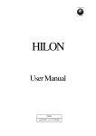
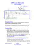
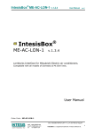
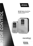
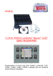
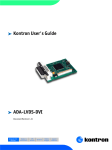
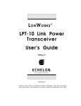
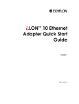
LonWorks (LN-01) User Manual Echelon, LON, LonMaker, NodeBuilder, LonBuilder, LonPoint, LNS, LONWORKS, LonTalk, i.LON, Neuron, 3120, 3150, LonMark, the LonUsers Logo, the Echelon Logo and the LonMark Logo are registered trademarks of Echelon Corporation. Other trademarks belong to their respective owners. The information supplied by this document is subject to change without notice. No responsibility or liability for the correctness of the information supplied within this document is assumed. Table of Contents Chapter 1 Overview .....................................................................................1-1 1.1 Introduction .........................................................................................1-1 1.2 LN-01 Communication Interface .........................................................1-1 1.3 Dimension...........................................................................................1-1 Chapter 2 Installation ..................................................................................2-1 2.1 Specification .......................................................................................2-1 2.2 Installation...........................................................................................2-1 2.3 Wiring .................................................................................................2-3 2.4 Network Initialization of LN-01 Communication Interface ...................2-4 2.5 Service Pin..........................................................................................2-4 2.6 Text Device Interface File (.XIF) .........................................................2-4 Chapter 3 Network configuration ...............................................................3-1 3.1 Network Topology...............................................................................3-1 3.2 Specification .......................................................................................3-1 3.3 Configuration ......................................................................................3-1 3.4 Replace LN-01....................................................................................3-1 Chapter 4 Using Network Variables on LN-01 Communication Interface4-1 4.1 Standard Network Variable Type (SNVT) Table .................................4-1 4.1.1 NVIs (network variables for inputting to Delta AC Drive).................. 4-1 4.1.2 NVOs (Network variables outputted to network integrated tool from the AC Drive) ................................................................................... 4-2 4.2 Functional Profile................................................................................ 4-3 4.3 Using LN-01 to Communicate with the AC Drive................................ 4-4 4.4 Read/Write AC Drive Parameters....................................................... 4-5 4.5 Run/Stop Command ........................................................................... 4-7 4.6 Sending Frequency Command to the AC Drive.................................. 4-7 Chapter 5 Troubleshooting......................................................................... 5-1 5.1 Power LED ......................................................................................... 5-1 5.2 SP LED............................................................................................... 5-2 5.3 Service LED ....................................................................................... 5-2 CHAPTER 1 OVERVIEW 1.1 Introduction This manual provides instructions of the installation and setup for LN-01 that used to communication with Delta AC Drives (firmware version of AC drive should conform with LN-01 as table 1-1 below) via LonWorks Network. Delta AC Drive Series Firmware Version VFD-B 4.00 以上 VFD-M 3.00 以上 VFD-S 2.50 以上 VFD-F 1.90 以上 Table 1-1 1.2 LN-01 Communication Interface LN-01 communication interface is a comprised of a control card with a Neuron chip. Through the use of LN-01 unit in the LonWorks Network, AC drives are able to communicate with other devices. 1.3 Dimension Revision November 2006, 5015616701 1-1 Chapter 1 Overview| LN-01 42.0 [1.65] SP 1 2 4 5 6 7 8 RS-485 92.0 [3.62] 107.0 [4.21] 100.0 [3.94] 3 9 1-2 67.0 [2.64] 57.2 [2.25] 34.0 [1.34] Revision November 2006, 5015616701 CHAPTER 2 INSTALLATION 2.1 Specification Power Supply 16-30VDC, 750mW Transmission Rate LonTalk Modbus: ASCII 7, N, 2, Baud rate: 9600 free topology with FTT-10A 78 Kbps LonTalk Terminal 9 terminals, wire gauge: 28-12 AWG, wire strip length: 7-8mm RS-485 Port 6 pins with RJ-11 2.2 Installation 1. Please refer to Figure 2-1 to mount LN-01 on the DIN rail. Figure 2-1 2. Table below shows LonTalk system wiring. RJ-11, a safety device, is used to prevent user plug-in the device in the wrong direction. Revision November 2006, 5015616701 2-1 Chapter 2 Installation| LN-01 Terminal Symbol Function 1 These are twisted pair cable connect to LonTalk system. Terminals 1 and 2 should be used as one group, and same for terminals 3 and 4. 2 3 4 5 N/A 6 N/A Power input terminals for 16-30 VDC. Power input is polarity sensitive. (No need to consider which polarity to connect. Need only connect 16-30 VDC to LN-01 input terminals directly) 7 8 Terminals 6 and 7 should be used as one group, and same for terminals 8 and 9 (see NOTE below). 9 Table 2-1: Terminal definition for LonTalk system NOTE If 16-30V DC input is connected to one group for example terminals 6&7,Lonworks then is connected to the other terminals group which is 8&9. Or vice versa. 3. LED indicator: Figure 2-2, sequence from top to bottom is Power LED, SP LED and service LED. 4. Service pin locates at the right lower corner of Service LED. 5. If power is on and LN-01 is not configured, LED status will be as follows: Power LED is steady green, SP LED is off (red or green) and service LED will blink in red LED at rate of 1/2 Hz. 6. Configuring the LN-01 by using Lonwork integrated tool. 7. After configuration, power LED, SP LED should be greenand service LED should be OFF. If LED shows differently, refer to user manual chapter 5 for troubleshooting. 2-2 Revision November 2006, 5015616701 Chapter 2 Installation| LN-01 2.3 Wiring Figure 2-2 NOTE Power input terminals/power output terminals (connected in parallel): If there is 16-30V DC input into one group (either V1 or V2), the other group then be used as power output terminals which are parallel connect to LonWorks device. Power input is polarity sensitive due to bridge rectification used inside. Revision November 2006, 5015616701 2-3 Chapter 2 Installation| LN-01 2.4 Network Initialization of LN-01 Communication Interface The LN-01 communication interface contains a Neuron chip with a unique address. LN-01 needs be initialized to get ready for communication interface after hardware installation. Setting node address on the Lonworks network is determined either via installation tools or via network management tools during the installation. Neuron ID is a 48 bits number used to identify each Neuron chip. LN-01 will send the Neuron ID via service pin to be identified in the Lonworks network. 2.5 Service Pin Bi-directional service pin is used to monitor the internal firmware status. As just mentioned above, LN-01 sends Neuron ID of Neuron chip to Lonworks via this pin. Before connecting to the LonWorks network via network tools, user needs to press the Service Pin (as shown in figure 2-2) to send the unique 48-bit neuron ID for LonWorks network identification. After successful configuration, LN-01 connects to the LonWorks network and the Service LED should be OFF. If Service LED is NOT OFF, it means that configuration is failed. Refer to chapter 5 Troubleshooting for details. 2.6 Text Device Interface File (.XIF) This file contains the definition of each interface device. Through use of network tools, user is capable of knowing the device in the network. File name “LN-01_xxx.XIF” is used by LN-01. This file, which saved in the disk, has topology of 78 Kbps. “xxx” in the file name describes the firmware version. 2-4 Revision November 2006, 5015616701 CHAPTER 3 NETWORK CONFIGURATION 3.1 Network Topology The network structure that LN-01 adopts is free topology. In hardware, LN-01 uses FT3150 (transceiver) and FT-X1 (communication transformer). (FT3150 and FT-X1 are designed to be used in pair) The terminal block is insensitive polarity due to FTX1 characteristics. 3.2 Specification RS-485 communication is in ASCII format with protocol 9600, 7, N, 2 LON supports Free Topology, Bit rate 78kbps and 64 devices per channel. 3.3 Configuration LN-01 will start its function in LonWorks network after configuring via LonWorks network integrated tool. After configuring, power LED, SP LED should be greenand service LED should be OFF. If LED shows differently, refer to chapter 5 troubleshooting for details. 3.4 Replace LN-01 When LN-01 is malfunction or can’t configure to network during operation, you can replace by a new LN-01 and execute “Replace” command in LonWorks integrated environment to make new LN-01 work properly. Revision November 2006, 5015616701 3-1 Chapter 3 Network configuration| LN-01 This page intentionally left blank 3-2 Revision November 2006, 5015616701 CHAPTER 4 USING NETWORK VARIABLES ON LN-01 COMMUNICATION INTERFACE 4.1 Standard Network Variable Type (SNVT) Table Modifying network variables input (NVIs) through Lonwork integrated tool is also to send command to the AC drive. Network variables output is only used for the monitor of network integrated tool but cannot change status. Refer to following for details. 4.1.1 NVIs (network variables for inputting to Delta AC Drive) SNVT type Field Min. Max. Command Variable Name STOP nviSTOP SNVT_switch state 0 1 1 RESET nviRESET SNVT_switch state 0 1 1 RUN nviRUN SNVT_switch state 0 1 1 JOG nviJOG SNVT_switch state 0 1 1 Forward/Reverse nviFDRV SNVT_switch state 0 1 1 Freq. Command nviFreqCmd SNVT_flow_p N/A 0 65534 0.01 Parameter Command nviParaCmd SNVT_preset N/A N/A N/A N/A (OFF) (ON) Resolution Table 4-1 nviSTOP: When state=1, AC drive will stop. nviRESET: Should AC drive fails such as LV, OC happened, nviRESET is used to display if that fault has been cleared. nviRUN: When state=1, AC drive will run. Revision November 2006, 5015616701 4-1 Chapter 4 Using Network Variables on LN-01 Communication Interface| LN-01 nviJOG: When state=1, AC drive will jog. nviFDRV: When state=1, it changes AC drive running direction. For example, if AC drive is forward, it changes to reverse. Or vice versa. nviFreqCmd: Using frequency command to AC drive. Refer to the example below for details. nviParaCmd: Read/write AC drive parameters. Refer to the example below (4.3) for details. NVs output from Delta AC Drive. 4.1.2 NVOs (Network variables outputted to network integrated tool from the AC Drive) Command Variable Name SNVT type Min. Max. Resolution Setting Frequency nvoF SNVT_freq_f 0 3.40282E38 N/A Actual Frequency nvoH SNVT_freq_f 0 3.40282E38 N/A User Define Unit nvoU SNVT_freq_f 0 3.40282E38 N/A Output Current nvoA SNVT_freq_f 0 3.40282E38 N/A Number of GROUP nvoGROUP SNVT_flow 0 65534 1 AC Drive Status nvoErrCODE SNVT_freq_f 0 3.40282E38 N/A Table 4-2 nvoF: Showing the AC drive frequency. NvoF will change to nviFreqCmd once nviFreqCmd is changed. nvoH: Showing the AC drive output frequency. nvoH=0 when drive stops. nvoH will increase gradually till nvoH=nvoF when drive runs. nvoU: Display user defined unit. nvoA: Display output current. 4-2 Revision November 2006, 5015616701 Chapter 4 Using Network Variables on LN-01 Communication Interface| LN-01 nvoGROUP: Showing the parameters group number of AC drive. It varies based upon AC drive model type and firmware version. nvoErrCODE: Showing the AC drive status. If nvoErrCODE=0, means AC drive works properly. If nvoErrCODE is greater than 0, means AC drive is abnormal and nvoErrCODE displays the error code. Using VFD-S drive (version 2.50) as example, nvoErrCODE is 14 when fault LV occurs. Please refer to the AC drive user manual for troubleshooting and fault correction. 4.2 Functional Profile The variable speed motor drive object is shown in the figure below: Revision November 2006, 5015616701 4-3 Chapter 4 Using Network Variables on LN-01 Communication Interface| LN-01 Figure 4-1 4.3 Using LN-01 to Communicate with the AC Drive The AC drive, that is connected to LonWorks network, is now can be monitored via LN-01 after LN-01 is configured. The AC drive parameters are now can be programmed via commands. Using the VFD-S series as examples, read/write the parameter of Run/Stop command and frequency command to the AC drive are shown below. 4-4 Revision November 2006, 5015616701 Chapter 4 Using Network Variables on LN-01 Communication Interface| LN-01 Before connecting to LN-01, the AC drive should be set as table 4-3. Delta AC drive VFD-B VFD-M VFD-S VFD-F Baud rate 9600 P09-01=01 P-89=01 P09-01=01 P09-01=01 ASCII 7, N, 2 P09-04=00 P-92=00 P09-04=00 Source of Frequency Command P02-00=04 or 05 P-00=04 P02-00=04 or 05 P02-00=04 Source of Operation Command P02-01=03 or 04 P-01=03 or 04 P02-01=03 or 04 P02-01=03 or 04 Max. Output Freq. P01-00=50~400 P-03=50~400 P09-04=00 P09-05=00 P01-00=50~400 P01-00=50~120 Table 4-3 4.4 Read/Write AC Drive Parameters NviParaCmd is used to read/write AC Motor Drive parameters LN_REPORT_VALUE (read parameters) LN_RECALL (write parameters) LN_LEARN_VALUE (no function) LN_LEARN_CURRENT (no function) LN_NUL (no function) Example 1: write 400 to AC drive parameter 05-11 nviParaCmd.learn=LN_RECALL nviParaCmd.selector=1291(decimal) *NOTE nviParaCmd.value[0]=0 (Not used) nviParaCmd.value[1]=0 (Not used) nviParaCmd.value[2]=01 (High byte) nviParaCmd.value[3]=90 (Low byte) nviParaCmd.day=0 nviParaCmd.hour=0 nviParaCmd.minute=0 Revision November 2006, 5015616701 4-5 Chapter 4 Using Network Variables on LN-01 Communication Interface| LN-01 nviParaCmd.second=0 nviParaCmd.millisecond=0 NOTE Conversion is needed due to a different system numbers are used between nviParaCmd.selector and AC drive (nviParaCmd.selector uses decimal and AC drive parameters uses hexadecimal). Example of writing decimal 400 to parameter 05-11 of AC drive is illustrated below. Step 1: Convert 400 (decimal) to 0x0190 (hexadecimal) first, and fill in the high byte nviParaCmd.value[2] with 0x01 and low byte nviParaCmd.value[3] with 0x90. Step 2: Convert the parameter 05-11 value 0x050B in hexadecimal, to decimal 1291 and then nviParaCmd.selector=1291 nviParaCmd.value[2]=01 nviParaCmd.value[3]=90 Now decimal 400 can be written into AC drive parameter 05-11. Parameter Settings 05.11 400 Delta AC Drive 0x050B (hex) After conversion 1291 (decimal) LN-01 NVs nviParaCmd=1291 0x0190 (hex) nviParaCmd.value[2]=01 nviParaCmd.value[3]=90 Table 4-4 Example 2: read parameter 02-02 of AC drive nviParaCmd.learn=LN_REPORT_VALUE nviParaCmd.selector=514(decimal) * NOTE nviParaCmd.value[0]=0 (Not used) nviParaCmd.value[1]=0 (Not used) nviParaCmd.value[2]=0 (Not used) nviParaCmd.value[3]=1 nviParaCmd.day=0 nviParaCmd.hour=0 4-6 Revision November 2006, 5015616701 Chapter 4 Using Network Variables on LN-01 Communication Interface| LN-01 nviParaCmd.minute=0 nviParaCmd.second=0 nviParaCmd.millisecond=0 NOTE Again, conversion is needed due to different system numbers are used between nviParaCmd.selector and the AC drive (nviParaCmd.selector is in decimal and AC drive parameters are in hexadecimal). Example below illustrates read AC drive parameter 0202. Step 1: Parameter 02-02 is 0x0202 (hexadecimal). Step 2: Convert 0x0202 (hexadecimal) to 514 (decimal). Then set nviParaCmd.selector=514 to read AC drive parameter 02-02. Delta AC Drive After conversion LN-01 NVs Parameter Settings 02.02 N/A 0x0202 (hex) N/A 514 (decimal) nviParaCmd=514 nviParaCmd.value[2]=00 nviParaCmd.value[3]=01 Table 4-5 4.5 Run/Stop Command nviRUN.state=1, AC drive runs nviSTOP.state=1, AC drive stops Functions above are valid only when the operation command source is set to RS-485 first. 4.6 Sending Frequency Command to the AC Drive Revision November 2006, 5015616701 4-7 Chapter 4 Using Network Variables on LN-01 Communication Interface| LN-01 Function above is valid if the operation command source and frequency command source are set to RS-485 first. Take VFD-S AC drive for example, if you want to set frequency to greater than 60.00 Hz, the Max output frequency shall be set to greater than 60.00Hz first (refer to Table 4-3 to set Max. output frequency). If user wants to set frequency to 75.40Hz (nviFreqCmd=75.40), it should set Max output frequency in Table 4-3 to 75.40Hz first. . 4-8 Revision November 2006, 5015616701 CHAPTER 5 TROUBLESHOOTING There are three LEDs in front panel of LN-01. If the communication is normal, power LED, SP LED should be green (red LED means abnormal communication) and service LED should be OFF. If LEDs display do not match, refer to the below for details. 5.1 Power LED State Description Green LED Power is on and LN-01 works. LED is OFF Power on or program is abnormal Revision November 2006, 5015616701 Corrective Actions 1. Check if power is 24V or plug is loose. 2. Check if flash memory IC is wellinserted to the socket. 5-1 Chapter 5 Troubleshooting|LN-01 5.2 SP LED State Description Corrective Actions Green LED It communicates to AC drive Blinked LN-01 reads default setting from Green LED AC drive Disconnect or time-out Red LED 1. Check if cable is loose. 2. Check if the communication protocol is properly set. 5.3 Service LED State Description LED blinks at 1/2 Hz rate This is the normal situation for an unconfigured device LED is OFF Bad hardware device LED is ON continuously, even when power is first applied to the device. Bad hardware device LED blinks at powerup, goes OFF, then ON solid. This is the normal situation for an application-less device. 5-2 Corrective Actions Check if anything wrong with power supply, clock or Neuron chip. Check if anything wrong with power supply, clock or Neuron chip. Check if there is a short circuit between pin 17 and 18. If the device is not an applicationless, then it could be memory problems or application code errors. A self-test failure can also turn the LED ON solid. Revision November 2006, 5015616701