1
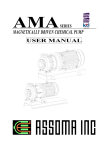
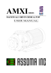
AMF⁄AMF-B
SERIES
CARTRIDGE/BAG FILTER-PUMP
USER MANUAL
Table of Contents
1. Foreword ........................................................................... 1 2. Installation and Piping ....................................................... 1 3. Priming Instructions and Notes ......................................... 2 4. Inspections and Maintenance ............................................ 3 5. Troubleshooting................................................................. 5 Appendix A: Exploded View and Parts List of AMF ............. 6 Appendix B: Exploded View and Parts List of AMF-B ......... 7 AMF SERIES
1. Foreword
Thank you for purchasing an AMF Series filter-pump. To ensure proper operation and
maximum efficiency, please read this instruction manual carefully. Failure to follow the
recommended operating conditions outlined in this manual may result in serious personal
injuries and/or equipment damage.
2. Installation and Piping
2.1 Pre-Installation Inspection
(1) Check the filter-pump exterior for any physical damage that may have been incurred
during shipping.
(2) Use a small screwdriver to rotate the impeller of the motor’s cooling fan. The fan
should turn easily. If the fan feels tight or if there are unusual sounds, the interior of the
pump may have been damaged during shipping.
(3) If there is any damage to the pump, contact the shipping company and the distributor
immediately to determine who should pay for the damage, and to arrange for
replacement parts.
(4) The filter and pump each has a nameplate, indicating the model, MFG number, rated
head, flow rate, and motor power, voltage, frequency etc. Check these data to ensure
they comply with your order and application.
2.2 Installation
(1) The filter-pump system should be installed on a leveled surface, with the weight of the
filter-pump evenly distributed.
(2) The AMF filter-pump is coupled with a rear pullout pump. The pressure gauge and
priming cup are located on the motor end of the system. Therefore, please take into
consideration the ease of operation and maintenance when installing the filter-pump.
(3) Do not disassemble the filter chamber from the base plate. If modification to the filter is
required, please contact ASSOMA INC. or authorized agent in your region.
The tightening torques of the cover fastener and position stud:
Model
Cover fastener
Position stud
AMF-12/24/36/54/B01/B02/B06
125±5 kgf‧cm
160±10 kgf‧cm
2.3 Suction/Discharge Piping
(1) For best performance, minimize the suction head by using straight, short piping.
Suction and discharge piping should be properly supported. The pump should not be
used as a means of providing support to the piping. When designing supports, consider
the effects of temperature changes on the supports to avoid thermal stress.
(2) The piping system should not have upward bumps that may collect air. The inlet piping
should also have a 0.01~0.02 slope increase towards the pump.
1
AMF SERIES
(3) Suction piping should be airtight. If air is allowed to seep into the suction piping and
into the pump, the pump might be damaged.
(4) There should not be any elbows for at least 5 times the pipe diameter from the opening
of the pump.
(5) The filter-pump system is not designed to bear the weight of the discharge piping.
Therefore, please ensure the necessary piping support is in place.
2.4 AMF Filter-Pump Specification
Capacity *
Model Cartridges / Bag
( l/hr)
Power **
( kW )
Inlet x Outlet
***
( mm )
Max.
Temp
( oC )
Max.
Pressure
( kg/cm2 )
AMF-1
10" x 1
450~900
0.065
15 x 15
70
0.8
AMF-2
20" x 1
600~1,200
0.065
15 x 15
70
0.8
AMF-4
20" x 2
1,800~3,600
0.18
25 x 25
70
1.5
AMF-6
20" x 3
2,700~5,400
0.25
25 x 25
70
1.5
AMF-12
20" x 6
5,000~10,000
0.4
40 x 40
70
2
AMF-16
20" x 8
6,000~12,000
0.75
40 x 40
70
3
AMF-24
20" x 12
9,600~19,200
1.5
50 x 50
70
4
AMF-36
20" x 18
12,000~24,000
2.2
50 x 50
70
4
AMF-54
30" x 18
16,000~32,400
3.75
65 x 50
70
4
AMF-B01
#01 x 1
5,000~12,000 0.4~0.75
40 x 40
70
4
AMF-B02
#02 x 1
9,600~36,000 1.5~3.75
50 x 50
70
4
AMF-B04
#04 x 1
1,800~5,400 0.18~0.25
25 x 25
70
1.5
AMF-B06
#06 x 1
5,000~12,000 0.4~0.75
40 x 40
70
4
Note:
*
The listed filtration capacity shown above is for reference only. The actual capacity will be
depending on the liquid property, the type of cartridge/bag and the resistance of the piping
system.
** In accordance with the required capacity of filtration, various models of the pump can be
selected to conform to the requirement.
*** Inlet and outlet dimensions can be changed to match customer’s requirement.
3. Priming Instructions and Notes
3.1 Priming Procedure
Action
Valve Status
Suction Priming Breeder Discharge
1. Inspect piping to ensure they are
properly connected and the top and
bottom covers are secured.
Open
2
Close
Close
Close
Drain
Close
AMF SERIES
Action
Valve Status
Suction Priming Breeder Discharge
Drain
2. Use a small screwdriver to check
the cooling fan of the motor.
3. Ensure all suction valves are
opened.
4. Open the priming valve and open
the breeder valve by 1/3. Perform
priming by pouring the liquid into
the priming cup. Continue until
liquid level stays constant.
Open
Open
Open 1/3
Close
Close
5. After priming, shut off the priming
valve and start the pump. (Be sure
to check the direction of rotation
of motor.) Keep breeder valve
open till priming is complete.
Open
Close
Open 1/3
Close
Close
Close
Open till
desired
flow rate
Close
6. Slowly open the discharge valve
till the desired pressure or flow
rate is achieved.
Open
Close
3.2 Notes in Operation
(1) The heart of the filter-pump system is the seal-less pump, which should be protected
from “Dry-Running”.
(2) If there is a power failure during operation, make sure to shut off the power to the
filter-pump system.
(3) During priming, keep the breeder valve open 1/3 to prevent the liquid from spraying out
too fast.
4. Inspections and Maintenance
4.1 Daily Inspection
Visual Inspection
1. Check the filter for corrosion and oxidation.
2. Check the pump, filter and piping for leaks
Operation Status
1. Check for abnormal vibration and noise.
2. Check tank liquid level, pressure gauge and flow meter.
4.2 Changing the Filter Cartridges
(1) The timing for changing the filter cartridges can be determined from the flow rate. The
cartridges should be changed if the discharge valve is fully opened and the desired flow
rate still cannot be reached.
3
AMF SERIES
(2) If the flow rate is not an important factor, then the filter cartridges should be changed
based on the pressure drop according to the following table.
Model AMF-1/2 AMF-4/6 AMF-12 AMF-16 AMF-24 AMF-36/54 AMF-B01/02/06 AMF-B04
Pressure
Drop
(kg/cm2)
0.4
0.8
1
1.2
1.8
2
1.5
0.8
Note: (1) Pressure Drop (kg/cm2) = Filter Gauge Pressure – Discharge Pressure
= Filter Pressure Gauge – S.G. x Discharge Head (m)/10
(2) Above table shows maximum suggested pressure difference for changing the filter
cartridges. If pressure difference is above suggested value, the flow rate will be very
small, with diminished filtration effect. Furthermore, the service life of the pump
may also be affected. The flow rate must not be lower than the minimum
recommended flow rate for the pump used.
(3) The above suggested pressure difference is for PP material Meltblown type filter
cartridges, with a viscosity of 1 cp.
4.3 Procedure for Changing Filter Cartridges
Action
Valve Status
Suction
Priming
Breeder Discharge
Drain
Close
Close
Open 1/3
Close
Open
Open
Close
Close
Close
Close
1. Shut off power
2. Open breeder valve and drain
valve and drain the liquid from the
filter chamber.
3. Loosen the swivel stud and
remove the top cover.
4. Loosen the cartridge fasteners and
remove the used cartridges.
5. Rinse the interior of the filter
chamber.
6. Put in the new cartridges and
secure the fasteners.
7. Replace the top cover and fasten
the swivel studs.
8. Rinse the filter exterior to remove
excessive chemicals from the
metallic parts. Take special care
not to wet the electrical parts.
Note: During draining, the discharge valve should be closed to prevent siphoning effect.
4
AMF SERIES
5. Troubleshooting
Failure
Possible Reasons
Remedy
No reading on pressure
gauge but flow seems
normal
1. Damaged pressure gauge. 1. Change pressure gauge.
2. Vacuum inside pressure 2. Remove gauge and replace the
gauge is broken.
vacuum tape.
High pressure with
insufficient or no flow rate
1. Discharge valve closed or 1. Open discharge valve to
not opened sufficiently.
desired flow rate.
2. Cartridges clogged.
2. Change the cartridges.
Low flow rate and low
pressure
1. Wrong direction of
rotation.
2. Incorrect RPM or pole.
3. Suction pipe blocked.
4. Air in the inlet piping.
1. Motor should rotate clockwise
as viewed from the motor end.
2. Clean suction piping.
3. Check suction piping.
No flow and no pressure
Damaged pump.
Read pump users manual.
Particles still present after
filtration
1. Cartridge fastener not
tight enough.
2. Cartridges are deformed
or damaged.
1. Tighten the fasteners.
1. Top or bottom cover is
not tightened.
2. Top or bottom O-Ring
seal not properly
installed.
3. Top or bottom O-Ring
seal corroded.
1. Tighten top and bottom
covers.
2. Check O-Ring seal.
Pump is leaking
Read pump users manual.
Read pump users manual.
Abnormal vibrations
Read pump users manual.
Read pump users manual.
Motor is overloaded
Read pump users manual.
Read pump users manual.
Filter chamber is leaking
5
2. Change the cartridges
3. Change O-Ring seal.
AMF SERIES
Appendix A: Exploded View and Parts List of AMF
No.
Part Name
No.
Part Name
1
Top cover
11
Manifold
2
Cover packing
12
Upper bracket
3
Cartridge fastener
13
Pressure gauge assembly
4
Filter chamber
14
Cover fastener
5
Cartridge core pipe
15
Vent valve
6
Swivel stud
16
Priming cup
7
Lower bracket
17
Main frame
8
Position stud
18
Motor guard
9
Base plate
19
Pump skid
10
Base plate packing
1
2
12
13
3
14
4
5
6
15
7
8
9
16
17
10
18
11
19
6
AMF SERIES
Appendix B: Exploded View and Parts List of AMF-B
No.
Part Name
No.
Part Name
1
Top cover
12
Base plate
2
Cover packing
13
Base plate packing
3
Retainer
14
Position stud
4
Retainer
15
Spring
5
Packing
16
Bolt
6
Filter chamber
17
Upper bracket
7
O-ring
18
Pressure gauge assembly
8
Swivel stud
19
Cover fastener
9
Bag
20
Vent valve
10
Basket
21
Priming cup
11
Lower bracket
22
Main frame
1
2
15
3
16
4
5
17
6
7
18
8
19
9
20
10
21
11
22
12
13
14
7