1
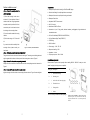
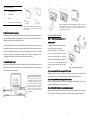
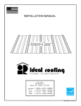
Waterproof Marine Audio Kit for MP-3 Player and iPhone/iTouch/iPod Installation Manual Greness Enterprise Co., Ltd. 1F, 19-1. Lane 39. Sec2. Jianguo South Road, Da’ an Dist., Taipei, Taiwan, R.O.C TEL: +886-2-2707-5741 FAX: +886-2-2707-4992 Website: www.greness.com.tw ®Copyright 2010 Greness Enterprise Co., Ltd. All rights reserved. All content subjects to modification without notice. Contents 8. Loudspeaker Installation Manual Introduction ………………………………………………………………………………….………………………………….1 Read the following installation manual carefully before proceeding. If you are unfamiliar with wiring Applications ……………………………………………………………………………………….……………………………1 electronic devices, consult your local dealer or contract professionals. False wiring could damage the Safety precaution …………………………………………………………………………………………….………………..1 amplifier and the rest of audio system. Specification ………………………………………………………………………………………….………………………...2 Parts list …………………………………………………………………………………………………………….…………..2 Jet-engine speaker installation manual Select the best location for mounting …………………………………………………………………………….………….3 1) Mount the plastic bracket on the chosen flat Amplifier installation manual ……………………………………..……….……………………………………………..……3 Loudspeaker installation manual ……………………………………..………………..………………………………….…6 surface with the screws provided in the package 2) Hold the jet-engine speaker in position and 1. Introduction secure the mounting with a screw and a nut The SM-200 and SM-300 are designed to provide the maximum waterproof protection to your 3) Adjust the projecting angle of the speaker and audio/MP-3 player. The housings are compatible with most of the audio devices with a 3.5mm plug tighten the screw and they are intended for use in a marine environment. There is a built-in microphone which would If you are in doubt with the stability of the mounting allow you to have a voice conversation while still the front cover is down. The housings are designed surface, please consult your local dealer. to be waterproof with IP 65 rating. However, direct submersion of the housing under water may induce damage to the unit and your audio/MP-3 player. Flush-mount speaker installation manual 1) Select a mounting location which will allow the speaker to lay flat and has adequate space. Keep the front cover down to provide the maximum protection. After any user operation, close the front cover and ensure the seal is complete. The unit will provide protection against splashes of water, dust, sand and other substances. 2) Use the supplied template to mark the mounting holes. See Figure1. 3) Drill a starter hole in the center of the mounting hole and use a hacksaw blade or a similar tool, cut the mount hole. 2. Applications 4) Drill the four 1/8" mounting holes. SM-200 and SM-300 are built to withstand tough challenges in different outdoor / marine 5) Connect the speaker wire to the speaker terminals and route to stereo. Be sure stripe wire is environments. They can be installed at locations with high humidity and high chance of water connected to the positive (+) terminal of speaker. See Figure2. splashes (SPA room, sauna, swimming pool, etc). Vehicles suitable for SM-200/SM-300 installation 6) Slide the four U-Clips over the mounting holes and press to hold in place. See Figure3. 7) Place a bead of RTV sealant (or equivalent) around the back rim of speaker basket. include: Motorbike Utility task vehicle (UTV) Personal watercraft (PWC) Golf car All terrain vehicle (ATV) Recreational vehicle (RV) Snowmobile Watercraft / boat 8) Secure the unit with provided screws for integrated speakers. Or for flush-mount speakers, tighten the screws to secure the unit first before fitting the cover grille onto the speaker. If you are in doubt with the stability of the mounting surface, please consult your local dealer. 3. Safety Precaution Read the manual before installation. It contains important information for all users. Turn off the electricity supply before beginning the installation For electric drill, ensure it is connected to the ground properly and the area is free of any liquid. If any problem occurs during the installation, please contact your local dealer for advice before proceeding. Contract professionals if necessary. 1 6 Surface installation manual 4. Specification Step 1 – Prepare the mounting surface for Waterproof Amplifier Audio Housing for iPod/iPhone/MP3 player SM-300 installation Small and deft design for multiple applications as motorcycle 1) Ensure the mounting location has a Waterproof and corrosion-proof plastic housing and bracket minimum of 120 mm depth and is free of Waterproof fuse holder cables and fuel lines. Using the gasket as Adjustable ON/OFF volume control a template, mark the positions of the four AUX 3.5 mm jack screw holes plus the hole used to insert Handsfree mini MIC for iPhone the housing on the mounting surface. Accessories:4 pins 3.5 plug cable, stainless hardware, packing/gasket, U-type bracket and thumbwheel screws 2) Cut out the surface marked for housing insertion. 600 hrs UV stabilized (ASTM D4329 & ASTM D2244) 3) Drill the holes using a 1/6” / 3.2mm drill 400 hrs Saltwater Spray Test (ASTM B117) bit. IP 65 Rating If you are in doubt with the stability of the RoHS confirmed mounting surface, please consult your Power supply:13.8V / DC 12V local dealer. Max power handling:30W Step 2 – Position the gasket into the back of SM-300 unit Impedance:4 ohms The groove can be found on the back of the audio housing unit. Trace the groove with the gasket and Frequency response:20Hz – 20kHz Figure 6. A summary of SM-300 installation. align the gasket with the holes on the front panel of the housing unit as shown in Figure 6. Step 3 – Connect the wires to the corresponding terminals Identify each color-coded wire and connect each wire to the corresponding terminal as instructed in 5. Audio Housing Parts List Please check the parts and their quantity before installing SM-200 / SM-300. Contact your local dealer if anything is missing as soon as possible. Figure 3. Step 4 – secure the housing unit on the mounting surface Align the housing unit with the holes on the mounting surface as shown in Figure 6. Insert and tighten Item Qnty Description A 1 SM-200 audio housing B 8 Mounting screw C 1 Audio cable with 3.5mm 4-pin plugs D 2 Thumbwheel screw E 1 Housing holder F 1 Bracket Table 1 lists all the parts included in the SM-200 package. 5 Figure 1. Parts of SM-200. (A) SM-200 audio housing (B) mounting screw ×8 (C) audio cable with 3.5mm 4-pin plugs (D) thumbwheel screw ×2 (E) housing holder (F) Bracket 2 A B C Item Qnty Description A 1 SM-300 audio housing B 4 Mounting screw C 1 Gasket D 1 Audio cable with 3.5mm 4-pin plugs Table 2 lists all the parts included in the SM-300 package. Figure 4. A summary of how to operate SM-200. (A) SM-200 unit (front cover opened) and MP-3 player out to allow user operation. (B) SM-200 unit (front cover closed) and MP-3 player positioned on the deck. (C) Close the front cover to provide the maximum waterproof protection. Figure 2. Parts of SM-300. (A) SM-300 audio housing (B) mounting screw ×4 (C) gasket (D) audio cable with 3.5mm 4-pin plugs 6. Select the best location for mounting Be aware that SM-200 and SM-300 have different mounting styles and each follows a separate set of In-dash installation manual installation instructions. SM-200 is designed to stand on top of a strong surface (Figure 5); SM-300 is Step 1 – Install the mounting bracket to the intended to be installed into a sturdy panel (Figure 6). mounting surface The surface/panel you select should have the appropriate strength to hold the unit firmly in place 1) Using the mounting bracket as a template, after installation. Apart from the strength, consider the effects of shock, vibration, shear pressure and mark four holes to mount the bracket. movement in different directions have on the mounting surface/panel. If the surface is not sturdy 2) Drill the holes using a 1/6” / 3.2mm drill bit. enough, the housing may be dislocated from its original position and it may be damaged. If you are 3) Hold the bracket against the mounting uncertain about the location of your choice, contact the local dealer for advice. surface. Insert and tighten four mounting screws until the bracket is securely mounted. 7. Amplifier Installation Manual If you are in doubt with the stability of the Read the following installation manual carefully before proceeding. If you are unfamiliar with wiring mounting surface, please consult your local electronic devices, consult your local dealer or contract professionals. False wiring could damage the dealer. amplifier and the rest of audio system. Step 2– Assemble SM-200 audio housing unit with the holder Figure 5. A summary of SM-200 installation. Insert the housing unit into the housing holder and hold them firmly together. Insert and tighten four Figure 3. Wiring diagram of SM-200 / SM-300. Connect the red and the black wires to DC 12V the main power supply and ground respectively. Connect the other wires to the speakers according to the wiring plan. Connect the grey wire to the positive terminal and the grey/white wire to the negative terminal of the right speaker. Connect the white wire to the positive terminal and the white/black wire to the negative terminal of the right speaker. mounting screws via the holes on the front panel of the housing unit as shown in Figure 5. Step 3 – Assemble SM-200 audio housing unit with its bracket Align the housing holder with the holes in the mounting bracket as demonstrated in Figure 5. Insert and tighten the thumbwheel screw into the housing unit. Step 4 – Wire SM-200 unit to the main power supply and speakers Identify each color-coded wire and connect each wire to the corresponding terminal as instructed in Figure 3. Finally use cable ties to secure the wires out of harms way to complete the installation. 3 4 A B C Item Qnty Description A 1 SM-300 audio housing B 4 Mounting screw C 1 Gasket D 1 Audio cable with 3.5mm 4-pin plugs Table 2 lists all the parts included in the SM-300 package. Figure 4. A summary of how to operate SM-200. (A) SM-200 unit (front cover opened) and MP-3 player out to allow user operation. (B) SM-200 unit (front cover closed) and MP-3 player positioned on the deck. (C) Close the front cover to provide the maximum waterproof protection. Figure 2. Parts of SM-300. (A) SM-300 audio housing (B) mounting screw ×4 (C) gasket (D) audio cable with 3.5mm 4-pin plugs 6. Select the best location for mounting Be aware that SM-200 and SM-300 have different mounting styles and each follows a separate set of In-dash installation manual installation instructions. SM-200 is designed to stand on top of a strong surface (Figure 5); SM-300 is Step 1 – Install the mounting bracket to the intended to be installed into a sturdy panel (Figure 6). mounting surface The surface/panel you select should have the appropriate strength to hold the unit firmly in place 1) Using the mounting bracket as a template, after installation. Apart from the strength, consider the effects of shock, vibration, shear pressure and mark four holes to mount the bracket. movement in different directions have on the mounting surface/panel. If the surface is not sturdy 2) Drill the holes using a 1/6” / 3.2mm drill bit. enough, the housing may be dislocated from its original position and it may be damaged. If you are 3) Hold the bracket against the mounting uncertain about the location of your choice, contact the local dealer for advice. surface. Insert and tighten four mounting screws until the bracket is securely mounted. 7. Amplifier Installation Manual If you are in doubt with the stability of the Read the following installation manual carefully before proceeding. If you are unfamiliar with wiring mounting surface, please consult your local electronic devices, consult your local dealer or contract professionals. False wiring could damage the dealer. amplifier and the rest of audio system. Step 2– Assemble SM-200 audio housing unit with the holder Figure 5. A summary of SM-200 installation. Insert the housing unit into the housing holder and hold them firmly together. Insert and tighten four Figure 3. Wiring diagram of SM-200 / SM-300. Connect the red and the black wires to DC 12V the main power supply and ground respectively. Connect the other wires to the speakers according to the wiring plan. Connect the grey wire to the positive terminal and the grey/white wire to the negative terminal of the right speaker. Connect the white wire to the positive terminal and the white/black wire to the negative terminal of the right speaker. mounting screws via the holes on the front panel of the housing unit as shown in Figure 5. Step 3 – Assemble SM-200 audio housing unit with its bracket Align the housing holder with the holes in the mounting bracket as demonstrated in Figure 5. Insert and tighten the thumbwheel screw into the housing unit. Step 4 – Wire SM-200 unit to the main power supply and speakers Identify each color-coded wire and connect each wire to the corresponding terminal as instructed in Figure 3. Finally use cable ties to secure the wires out of harms way to complete the installation. 3 4 Surface installation manual 4. Specification Step 1 – Prepare the mounting surface for Waterproof Amplifier Audio Housing for iPod/iPhone/MP3 player SM-300 installation Small and deft design for multiple applications as motorcycle 1) Ensure the mounting location has a Waterproof and corrosion-proof plastic housing and bracket minimum of 120 mm depth and is free of Waterproof fuse holder cables and fuel lines. Using the gasket as Adjustable ON/OFF volume control a template, mark the positions of the four AUX 3.5 mm jack screw holes plus the hole used to insert Handsfree mini MIC for iPhone the housing on the mounting surface. Accessories:4 pins 3.5 plug cable, stainless hardware, packing/gasket, U-type bracket and thumbwheel screws 2) Cut out the surface marked for housing insertion. 600 hrs UV stabilized (ASTM D4329 & ASTM D2244) 3) Drill the holes using a 1/6” / 3.2mm drill 400 hrs Saltwater Spray Test (ASTM B117) bit. IP 65 Rating If you are in doubt with the stability of the RoHS confirmed mounting surface, please consult your Power supply:13.8V / DC 12V local dealer. Max power handling:30W Step 2 – Position the gasket into the back of SM-300 unit Impedance:4 ohms The groove can be found on the back of the audio housing unit. Trace the groove with the gasket and Frequency response:20Hz – 20kHz Figure 6. A summary of SM-300 installation. align the gasket with the holes on the front panel of the housing unit as shown in Figure 6. Step 3 – Connect the wires to the corresponding terminals Identify each color-coded wire and connect each wire to the corresponding terminal as instructed in 5. Audio Housing Parts List Please check the parts and their quantity before installing SM-200 / SM-300. Contact your local dealer if anything is missing as soon as possible. Figure 3. Step 4 – secure the housing unit on the mounting surface Align the housing unit with the holes on the mounting surface as shown in Figure 6. Insert and tighten Item Qnty Description A 1 SM-200 audio housing B 8 Mounting screw C 1 Audio cable with 3.5mm 4-pin plugs D 2 Thumbwheel screw E 1 Housing holder F 1 Bracket Table 1 lists all the parts included in the SM-200 package. 5 Figure 1. Parts of SM-200. (A) SM-200 audio housing (B) mounting screw ×8 (C) audio cable with 3.5mm 4-pin plugs (D) thumbwheel screw ×2 (E) housing holder (F) Bracket 2 Contents 8. Loudspeaker Installation Manual Introduction ………………………………………………………………………………….………………………………….1 Read the following installation manual carefully before proceeding. If you are unfamiliar with wiring Applications ……………………………………………………………………………………….……………………………1 electronic devices, consult your local dealer or contract professionals. False wiring could damage the Safety precaution …………………………………………………………………………………………….………………..1 amplifier and the rest of audio system. Specification ………………………………………………………………………………………….………………………...2 Parts list …………………………………………………………………………………………………………….…………..2 Jet-engine speaker installation manual Select the best location for mounting …………………………………………………………………………….………….3 1) Mount the plastic bracket on the chosen flat Amplifier installation manual ……………………………………..……….……………………………………………..……3 Loudspeaker installation manual ……………………………………..………………..………………………………….…6 surface with the screws provided in the package 2) Hold the jet-engine speaker in position and 1. Introduction secure the mounting with a screw and a nut The SM-200 and SM-300 are designed to provide the maximum waterproof protection to your 3) Adjust the projecting angle of the speaker and audio/MP-3 player. The housings are compatible with most of the audio devices with a 3.5mm plug tighten the screw and they are intended for use in a marine environment. There is a built-in microphone which would If you are in doubt with the stability of the mounting allow you to have a voice conversation while still the front cover is down. The housings are designed surface, please consult your local dealer. to be waterproof with IP 65 rating. However, direct submersion of the housing under water may induce damage to the unit and your audio/MP-3 player. Flush-mount speaker installation manual 1) Select a mounting location which will allow the speaker to lay flat and has adequate space. Keep the front cover down to provide the maximum protection. After any user operation, close the front cover and ensure the seal is complete. The unit will provide protection against splashes of water, dust, sand and other substances. 2) Use the supplied template to mark the mounting holes. See Figure1. 3) Drill a starter hole in the center of the mounting hole and use a hacksaw blade or a similar tool, cut the mount hole. 2. Applications 4) Drill the four 1/8" mounting holes. SM-200 and SM-300 are built to withstand tough challenges in different outdoor / marine 5) Connect the speaker wire to the speaker terminals and route to stereo. Be sure stripe wire is environments. They can be installed at locations with high humidity and high chance of water connected to the positive (+) terminal of speaker. See Figure2. splashes (SPA room, sauna, swimming pool, etc). Vehicles suitable for SM-200/SM-300 installation 6) Slide the four U-Clips over the mounting holes and press to hold in place. See Figure3. 7) Place a bead of RTV sealant (or equivalent) around the back rim of speaker basket. include: Motorbike Utility task vehicle (UTV) Personal watercraft (PWC) Golf car All terrain vehicle (ATV) Recreational vehicle (RV) Snowmobile Watercraft / boat 8) Secure the unit with provided screws for integrated speakers. Or for flush-mount speakers, tighten the screws to secure the unit first before fitting the cover grille onto the speaker. If you are in doubt with the stability of the mounting surface, please consult your local dealer. 3. Safety Precaution Read the manual before installation. It contains important information for all users. Turn off the electricity supply before beginning the installation For electric drill, ensure it is connected to the ground properly and the area is free of any liquid. If any problem occurs during the installation, please contact your local dealer for advice before proceeding. Contract professionals if necessary. 1 6 Waterproof Marine Audio Kit for MP-3 Player and iPhone/iTouch/iPod Installation Manual Greness Enterprise Co., Ltd. 1F, 19-1. Lane 39. Sec2. Jianguo South Road, Da’ an Dist., Taipei, Taiwan, R.O.C TEL: +886-2-2707-5741 FAX: +886-2-2707-4992 Website: www.greness.com.tw ®Copyright 2010 Greness Enterprise Co., Ltd. All rights reserved. All content subjects to modification without notice.