1
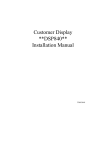
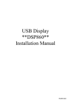
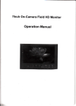
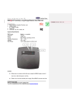
Customer Display
**DSP860**
Installation Manual
TM951045
Required Items
The following items are used to attach the Display to the Stand.
DISPLAY
STAND
EXTENSION SUPPORT (DSP840)
PILLAR A
PILLAR B
PILLAR C
ACCESSORY UNIT (DSP840)
DISK
CABLE TO PC
WAS-1540
CABLE TO PRINTER
WAS-1539
SCREW BAG
POWER CABLE FROM PC
Remrk: CABLE TO PRINTER (WAS-1539) is an optional item.
1
Assembling Steps
1. Get the Stand and the Stand Plate.
STAND
STAND PLATE
2. Get the DISPLAY unit and place the Cable from the Display
through the extension pillars to the Stand.
When extending the height of the Stand, attach the extension
pillars with different heights: Low, Mid-low, Mid-high and
High shown as below to the Stand.
2
3. Insert the tab on the Display (or the extension Pillar) into the
hole on the Stand until you feel it clicked.
4. Connect the cable from the Display to the RJ connector (TO
DSP) inside the Stand until you feel it clicked.
Also connect the enclosed D-connector cable (CABLE TO
PC) to the “ To Host ” connector and plug the power cable
(POWER CABLE FROM PC) into the DC Jack (DC 12V)
and connect the optional Printer D-connector cable (CABLE
TO PRINTER) to the “ To Printer ” connector when needed
Note:CABLE TO PRINTER (WAS-1539) is an optional
item You may order it when needed.
3
5. Cover the Stand Plate back and fasten the screws.
Mounting hole to fit
the special screw
6. You may use the enclosed m ounting screws (one Special
screw and two Wood screws) to fix the Display on the
wooden table surface.
Get the Mounting hole on the Stand Plate to fit the Special
screw first and then fix the two Wood screws.
Wood screw
Special screw
Wood table surface
4
The Display/Pillar/Stand Dimensions
5
The Display/Pillar/Stand Dimensions
6
7