1
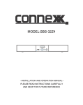
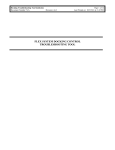
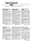
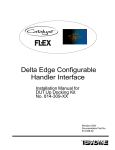
J750 Test System Probe Card
Debug Tool Installation Manual
613-504-00 Rev. A
T
Because Testing Matters
J750 Test System Probe Card Debug Tool Installation Manual (613-504-00)
PN 613-504-00
Rev A
LIMITED REPRODUCTION RIGHTS
This document may be reproduced by a Teradyne Customer solely for internal use with authorized
systems by operators who have agreed to observe this restriction. Any copy of this document, or
portions thereof, must contain the copyright and proprietary rights notice as stated on the original.
Copyright © 2010 Teradyne, Inc. All rights reserved.
Printed in the U.S.A.
The material in this document is subject to change without notice. Teradyne, Inc. assumes no
responsibility for any errors which may appear in this document. This document contains trade secrets
and confidential information, and is furnished pursuant to a license to the user from Teradyne, Inc. Use
or reproduction of this document is restricted under the terms of the license.
RESTRICTED RIGHTS LEGEND
Use, duplication, or disclosure by the Government is subject to restrictions as set forth in subdivision
(b) (3) (ii) of the Rights in Technical Data and Computer Software clause at 52.227-7013.
CREDITS AND TRADEMARKS
Teradyne is a registered trademark of Teradyne, Inc. in the U.S. and other countries. All product names
are trademarks or registered trademarks of Teradyne, Inc. (including its subsidiaries) or their
respective owners.
Teradyne, Inc.
600 Riverpark Drive
North Reading, MA 01864
ii
J750 Test System Probe Card Debug Tool Installation Manual (613-504-00)
Table of Contents
About This Manual .................................................................................................... 1
Installation Manual ..................................................................................................... 1
Viewing This Document Online ................................................................................. 1
Additional Documentation ......................................................................................... 1
Revision History ......................................................................................................... 1
Overview .................................................................................................................... 2
Installation ................................................................................................................ 3
Overview ..................................................................................................................... 3
Unpacking the Probe Card Debug Tool.................................................................... 3
Installing the Probe Card Debug Tool ..................................................................... 3
Preparing the Tester ...................................................................................................................... 3
Installing the Probe Card Debug Tool ......................................................................................... 4
Personal Notes ......................................................................................................... 9
Manual Comment Form...........................................................................................10
iii
J750 Test System Probe Card Debug Tool Installation Manual (613-504-00)
List of Images
Probe Card Debug Tool Main Components ....................................................................2
PIB Installed on Tester ....................................................................................................4
Probe Tower Installed on PIB ..........................................................................................5
Spacer Position for both 1024 and 512-pin Tester Configuration .............................5
Base Ring Assy Assembled to Probe Tower ................................................................. 6
Top Ring Assembly with Latches and Probe Card .......................................................6
Probe Card Installed in Ring Assembly .........................................................................7
Mount Alignment Pin Location .......................................................................................7
Securing the Probe Card Using an Alternating Pattern ............................................. 8
iv
J750 Test System Probe Card Debug Tool Installation Manual (613-504-00)
About This Manual
Installation Manual
This manual describes how to install the J750 Test System Probe Card Debug Tool (p/n 610-11500) to the customer’s probe tower and probe card. All instructions assume that both the J750
tester and the prober are installed and fully operational.
This manual is intended for trained maintenance personnel. The local Teradyne Service office can
assist with any additional questions you may have about the J750 Test System or this tool.
We welcome any comments or feedback you have about this manual, the debug tool or the J750
Test System. Please send feedback to: [email protected].
For your convenience, we have also included a Manual Comment Form at the end of this
document.
Viewing This Document Online
When viewing this document online, you may click any hyperlink, cross-reference or page number
to jump to that topic.
Additional Documentation
The following documents may provide additional information when using this document:
•
•
J750 - 512 Pin Test System Service Reference Manual, p/n 552-360-33
J750 - 1024 Pin Test System Service Reference Manual, p/n 552-360-34
Revision History
Revision Date
A
Reason for Change
Initial Release
1
J750 Test System Probe Card Debug Tool Installation Manual (613-504-00)
Overview
The J750 Test System Probe Card Debug Tool (p/n 610-114-00) comes ready to assemble to the
customer’s probe tower and probe card. The main components of the tool are:
•
•
ME J750 Debug Tool Top Ring Assy (p/n 608-736-00)
ME J750 Debug Tool Base Ring Assy (p/n 608-737-00)
The tool is used to facilitate probe card troubleshooting by holding the card to the probe tower
while the tester is undocked from the prober.
The figure below shows the main components of the debug tool.
ME J750 Debug Tool Top Ring Assy
(p/n 608-736-00)
ME J750 Debug Tool Base Ring Assy
(p/n 608-737-00)
Probe Card Debug Tool Main Components
2
J750 Test System Probe Card Debug Tool Installation Manual (613-504-00)
Installation
Overview
The Installation section provides information and procedures for the following:
•
•
Unpacking the Probe Card Debug Tool
Installing the Probe Card Debug Tool
Unpacking the Probe Card Debug Tool
The tool is shipped in a single case. Prior to starting installation, open the case and ensure that
the following items are present:
•
•
•
ME J750 Debug Tool Top Ring Assy (p/n 608-736-00)
ME J750 Debug Tool Base Ring Assy (p/n 608-737-00)
J750 Test System Probe Card Debug Tool Installation Manual (p/n 613-504-00)
Installing the Probe Card Debug Tool
This section of the manual describes the procedures for installing the J750 Test System Probe
Card Debug Tool.
Note
These instructions assume that both the tester and prober are installed and are fully
operational. Do not attempt to install the kit if this is not the case.
The following tools are required to install the kit:
•
•
•
#1 phillips screwdriver
5/32” hex wrench
3/16” hex wrench
Perform the following steps to install the debug tool:
Preparing the Tester
Prior to installing the Probe Card Debug Tool, the J750 tester must be prepared as follows:
!
C
A
U
T
I
O
N
!
!
Always wear a tested grounding strap while working on the J750 tester.
1.
2.
3.
Ensure that the tester is fully undocked and a sufficient distance from the mating equipment.
Position the tester so that the DIB mounting surface faces up.
If installed, remove the probe tower form the tester.
!
C
A
U
T
I
O
N
!
!
Always ground the Customer PIB or calibration DIB when installing or
removing it from the DIB fixture on the tester.
4. If installed, properly ground the Customer PIB or Calibration DIB as outlined in the Grounding
Calibration and Customer DIBs section of the Maintenance Chapter of the J750 - 512 Pin Test
System Service Reference Manual or the J750 - 1024 Pin Test System Service Reference
Manual, as appropriate.
3
J750 Test System Probe Card Debug Tool Installation Manual (613-504-00)
5. Push the red Power Off switch on the front of the J750 tester to turn off power.
6. Place the DIB vacuum switch on the tester to the UNLOCK (off) position.
7. Remove the Customer PIB or Calibration DIB from the tester, then remove the ground
connection. Place the PIB/DIB onto a proper work surface.
Installing the Probe Card Debug Tool
!
C
A
U
T
I
O
N
!
!
Always wear a tested grounding strap while working on the J750 tester.
1.
Properly ground the customer PIB then place it onto the DIB fixture of the tester. The figure
below shows the PIB Installed onto the tester.
PIB Installed on Tester
2.
3.
Place the DIB vacuum switch on the tester to the LOCK (on) position.
Press down on the PIB to ensure it seats properly. Apply pressure to the PIB in the area
directly above the pogo blocks.
4. Remove the ground connection from the PIB.
5. Remove the four (4) phillips head screws from the bottom cover of the probe tower using the
no. 2 phillips screwdriver then remove the cover from the tower.
4
J750 Test System Probe Card Debug Tool Installation Manual (613-504-00)
6. Place the probe tower onto the PIB.
Probe Tower Installed on PIB
7.
The debug tool is shipped for use with a 1024 Pin Tester, if it is being used on a 512 Pin Tester
perform the following steps:
• Remove four (4) 1/4-20 BHCS #10-32 x3/8" SS.
• Remove the spacers from the counter bore hole and flip it over so that the 512 engraved
on the bottom of spacer faces up.
• Replace the spacer so that 512 engraving is visible. Secure the spacers with four (4) 1/420 BHCS #10-32 x3/8" SS.
• Replace the spacer so that 512 engraving is visible. Secure the spacers with four (4) 1/420 BHCS #10-32 x3/8" SS. The figure below shows setting for both 1024 and 512 pin
tester.
Using 1024-pin Tower
Flip to use with 512-pin Tower
Spacer Position for both 1024 and 512-pin Tester Configuration
5
J750 Test System Probe Card Debug Tool Installation Manual (613-504-00)
8. Once the spacers are properly configured, place 608-737-00 onto the probe tower. The
figure shows the mounts on probe tower.
Short side of these pins
align to tower hole and
slot--long side faces
upwards to align debug
tool top ring.
Base Ring Assy Assembled to Probe Tower
Note
Tighten the screws in a cross pattern, tightening each screw a little bit each time until
they are secure.
9. Secure the Base Ring Assy (608-737-00) to the probe tower using the four (4) 1/4-20 x 3"
(supplied with 608-737-00) long socket head screws. Tighten the screws using the 3/16” hex
wrench.
10. Place the Top Ring Assy (608-736-00) onto a proper anti-static work surface so that the four
(4) captive screw knobs face down and the two (2) lever assemblies face up.
11. Lift and turn the knobs on the ring assembly so that the latches are in the open position. The
figure below shows the latches open.
Latch Assembly
in closed position
Latch Assembly
in open position
Top Ring Assembly with Latches and Probe Card
6
J750 Test System Probe Card Debug Tool Installation Manual (613-504-00)
12. Place the probe card onto the ring assembly with the probe side down.
Note
Be sure to line up the pins on the ring assembly with the mating holes in the probe card.
13. Once the probe card is properly oriented in the ring assembly, close the latches to secure the
card in place. The figure below shows the probe card installed in the ring assembly.
Probe Card Installed in Ring Assembly
14. Remove the four (4) phillips head screws from the top cover of the probe tower using the
no. 2 phillips screwdriver then remove the cover from the tower.
15. Turn the Top Ring (608-736-00) over so that the probe side of the probe card faces down.
Note
Make sure to keep the ring assembly parallel to the tester as you place it onto the probe
tower.
16. While sliding the holes in the ring assembly over the alignment pins on the mounts, place the
ring assembly onto the probe tower. The figure below shows the alignment pin location.
Alignment Pins
Mount Alignment Pin Location
7
J750 Test System Probe Card Debug Tool Installation Manual (613-504-00)
17. Secure the Probe Card and Top Ring Assy. to the Base Ring Assy. by tightening the four
knobs. Tighten the knobs in an alternating pattern to ensure even compression of the signal
pins in the Signal Delivery tower as shown in the figure Securing the Probe Card Using an
Alternating Pattern. Tighten two knobs across from each other simultaneously.
• Knob Location 1 and 2
• Knob Location 3 and 4
3
1
2
4
Securing the Probe Card Using an Alternating Pattern
8
J750 Test System Probe Card Debug Tool Installation Manual (613-504-00)
Personal Notes
9
J750 Test System Probe Card Debug Tool Installation Manual (613-504-00)
Manual Comment Form
We appreciate your feedback. Your comments are a valuable source of information for
continuous improvement in our documentation effort. Please return this form together with a
copy of the pages of concern from the manual marked with your comments to the address at the
end of this form.
Name
Manual
Document No.
Revision No. and Date
Name
Sender
Company
Job Title
Address
1.
Briefly, in the space below, how would you describe this manual?
______________________________________________________________________
______________________________________________________________________
______________________________________________________________________
______________________________________________________________________
2.
How do you use this manual?
__ I read it from beginning to end.
__ I only read the sections that pertain to my immediate needs.
__ I only read the sections that pertain to my job.
__ I use this manual for training purposes.
__ I use this manual for reference purposes.
3.
When you need to find information in this manual, where is the first place that you
look:
__ Table of Contents
__ Thumb through the pages until I find what I am looking for
4. How easily can you find information in this manual?
1
2
3
4
Not easily
5
Very easy
5. How clear is the information in this manual?
1
2
3
4
Not clear
5
Very clear
6. When you actually try instructions in this manual, how easily can you follow them?
1
2
3
4
Not easily
7.
5
Very easy
How well did you understand the product before reading this manual:
1
2
Not at all
3
4
5
Very well
10
J750 Test System Probe Card Debug Tool Installation Manual (613-504-00)
8. After
1
2
3
4
Not at all
5
Very well
9. Was all of the information you needed included in this manual?
__ Yes
__ No
If not, what was missing?
_______________________________________________________________________
_______________________________________________________________________
_______________________________________________________________________
10. The best aspect of this manual is:
______________________________________________________________________
______________________________________________________________________
______________________________________________________________________
11. If you could change one aspect of this manual, what would it be:
_______________________________________________________________________
_______________________________________________________________________
_______________________________________________________________________
Other comments:
______________________________________________________________________
______________________________________________________________________
______________________________________________________________________
______________________________________________________________________
______________________________________________________________________
Return to:
Teradyne, Inc.
500 Riverpark Drive
North Reading, MA 01864
USA
Attn: J750 Product Support Department
Email: [email protected]
11