1
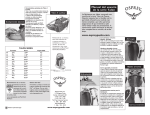
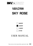
SS-41WM Quartet Mobile Backplane User’s Manual Features of product -- Frame: Aluminum material Interface: Support SAS, SATA-I, SATA-II Form Factor: 1 x 5.25” Bay for 4 x 2.5” SAS & SATA Hard Drive(SSD) High performance transfer rate up to SAS 6Gb/s & SATA 6Gb/s Support RAID 0,1,5 Functions (Need an optional SAS or SATA Raid Control card) Plug & play, hot swappable Key lock design for each single HDD tray Support 2.5” single hard drive up to 15mm thickness in height With 15Pin Power connector and 7Pin Signal connector Cooling fan: Built-in 2 X 4cm(4020) FAN LED for Power & HDD access Color for choice: Standard color is black [Other colors are options] Dim:175(L) X 146(W) X 42(H) mm Weight : 0.79KG Front tray: Plastic material SS-41WM --Solid HDD Inner tray with strip-heat ventilating holder -- Picture A-1 Picture A-2 HDD Installation: 1. For 2.5”SATA HDD(SSD), put it into the tray as it showed on Picture A-1 and use the provided screws to mount it on the HDD tray one by one. 2. For 2.5”SAS HDD or HDD with more than 10.5mm in height, loose the cover-mounting screw and remove the upper cover. And then, mount the SAS HDD or the thick HDD on the open tray (Note: after SAS HDD installed, do not put on the upper cover, because the SAS HDD height is higher (Picture A-2). This HDD tray can fit the HDD max to 14.5mm high. ---Safety Lock--The key lock design keeps the HDD inside the frame and prevents it being taken out while HDD is working. (See Picture B-1 & B-2) Open Picture B-1 Lock Picture B-2 a) LOCK (Picture B-1) Slide in the HDD tray and press the front handle to lock the HDD tray on the frame. Then, use the key to lock it( See picture B-1), b) OPEN (Picture B-2) Use the key to unlock it and use a finger to hold the “Clicker Lock” on the front panel and pull the HDD tray out( see Picture B-2) ---Front Panel & Real View--- C1--C4: HDD Tray C6 : LED (See Picture C & D) C5 : Key lock for HDD tray *Purple blinking while HDD is accessing. *Blue when HDD is installed * Note: When the HDD is installed but it is not powered on, there is no LED indication. Picture D D8: 15pin Power connector D9—D10: Cooling FAN D11, D12, D13, D14): For SATA or SAS data port connections to the host (SATA or SAS RAID controllers.) D15: HDD LED Switch Indication description: (a) When it is set to “ × “ position, the front LED does NOT blinking while it is accessing [ In this case, the hard drives will spin up when the system power is turned on ]. (b) When it is set to “ ○ ” position, it is blue blinking while the HDD is being accessing. [ In this case, the HDD does not spin up until the SATA initial signal is received ]. (c) The default setting for D15 (HDD LED Switch) is to “ ○ ” position(HDD LED Enable).