1
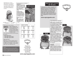
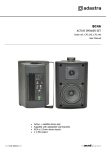
SS-40WM Quartet Mobile Backplane User’s Manual Features of product -- Frame: Aluminum material Interface: Support SAS, SATA-I, SATA-II Form Factor: 1 x 5.25” Bay for 4 x 2.5” SAS & SATA Hard Drive(SSD) High performance transfer rate up to SAS 6Gb/s & SATA 6Gb/s Support RAID 0,1,5 Functions (Need an optional SAS or SATA Raid Control Card) Plug & play, hot swappable Support 2.5” single hard drive up to 15mm thickness in height With 4Pin Power connector and 7Pin Signal connector Cooling fan: Built-in 2 X 4cm(4020) FAN LED for Power & HDD access Color for choice: Standard color is black [Other colors are options] Dim:175(L) X 146(W) X 42(H) mm Weight : 0.79KG Front tray: Plastic material --Solid HDD Inner tray with strip-heat ventilating holder -- Picture A-1 Picture A-2 HDD Installation: 1. For 2.5”SATA HDD(SSD), put it into the tray as it showed on Picture A-1 and use the provided screws to mount it on the HDD tray one by one. 2. For 2.5”SAS HDD or HDD with more than 10.5mm in height, loose the cover-mounting screw and remove the upper cover. And then, mount the SAS HDD or the thick HDD on the open tray (Note: after SAS HDD installed, do not put on the upper cover, because the SAS HDD height is higher(Picture A-2). This HDD tray can fit the HDD max to 14.5mm high. ---Safety Lock--The mechanical lock design keeps the HDD inside the frame and prevents it being taken out while HDD is working. (See Picture B1 & B2) Picture B-1 Picture B-2 a) LOCK Slide in the HDD tray and press the front handle to lock the HDD tray on the frame( See picture B-2). b) OPEN Use a finger to hold the “Clicker Lock” on the front panel and pull the HDD tray out( see Picture B-1) ---Front Panel & Real View--- (See Picture C & D) Picture C C1--C4: HDD Tray C5 : Mechanical lock for front panel C6 : Blue color blinking while HDD is accessing. No LED indication if HDD not accessing. Picture D D8: 4pin Power connector D9—D10: Cooling FAN D11, D12, D13, D14): For SATA or SAS data port connections to the host(SATA or SAS RAID controllers.) D15: HDD LED Switch Indication description : (a) When it is set to “ × “ position, the front LED does NOT blinking while it is accessing [ In this case, the hard drives will spin up when the system power is turned on ]. (b) When it is set to “○” position, it is blue blinking while the HDD is being accessing. [ In this case, the HDD does not spin up until the SATA initial signal is received ]. (c) The default setting for D18 (HDD LED Switch) is to “○” position(HDD LED Enable).