1
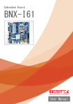
Embedded Board BNX-A77 Always at the forefront of innovation User Manual 1 Copyright This publication contains information that is protected by copyright. No part of it may be reproduced in any form or by any means or used to make any transformation adaptation without the prior written permission from the copyright holders. This publication is provided for informational purposes only. The manufacturer makes no representations or warranties with respect to the contents or use of this manual and specifically disclaims any express or implied warranties of merchantability or fitness for any particular purpose. The user will assume the entire risk of the use or the results of the use of this document. Further, the manufacturer reserves the right to revise this publication and make changes to its contents at any time, without obligation to notify any person or entity of such revisions or changes. © 2011. All Rights Reserved. Trademarks All trademarks and registered trademarks of products appearing in this manual are the properties of their respective holders. FCC and DOC Statement on Class A This equipment has been tested and found to comply with the limits for a Class A digital device, pursuant to Part 15 of the FCC rules. These limits are designed to provide reasonable protection against harmful interference when the equipment is operated in a residential installation. This equipment generates, uses, and can radiate radio frequency energy and, if not installed and used in accordance with the instruction manual, may cause harmful interference to radio communications. However, there is no guarantee that interference will not occur in a particular installation. If this equipment does cause harmful interference to radio or television reception, which can be determined by turning the equipment off and on, the user is encouraged to try to correct the interference by one or more of the following measures: Reorient or relocate the receiving antenna. Increase the separation between the equipment and the receiver. Connect the equipment into an outlet on a circuit different from that to which the receiver is connected. Consult the dealer or an experienced radio TV technician for help. Notice: 1. The changes or modifications not expressly approved by the party responsible for compliance could void the user’s authority to operate the equipment. 2. Shielded interface cables must be used in order to comply with the emission limits. 2 Warranty 1. Warranty does not cover damages or failures that are raised from misuse of the product, inability to use the product, unauthorized replacement or alteration of components and product specifications. 2. The warranty is void if the product has been subject to physical abuse, improper installation, modification, accidents or unauthorized repair of the product. 3. Unless otherwise instructed in this user’s manual, the user may not, under any circumstances, attempt to perform service, adjustments or repairs on the product, whether in or out of warranty. It must be returned to the purchase point, factory or authorized service agency for all such work. 4. We will not be liable for any indirect, special, incidental or consequential damages to the product that has been modified or altered. Static Electricity Precautions It is quite easy to inadvertently damage your PC, system board, components or devices even before installing them in your system unit. Static electrical discharge can damage computer components without causing any signs of physical damage. You must take extra care in handling them to ensure against electrostatic build-up. 1. To prevent electrostatic build-up, leave the system board in its anti-static bag until you are ready to install it. 2. Wear an antistatic wrist strap. 3. Do all preparation work on a static-free surface. 4. Hold the device only by its edges. Be careful not to touch any of the components, contacts or connections. 5. Avoid touching the pins or contacts on all modules and connectors. Hold modules or connectors by their ends. Important: Electrostatic discharge (ESD) can damage your processor, disk drive and other components. Perform the upgrade instruction procedures described at an ESD workstation only. If such a station is not available, you can provide some ESD protection by wearing an antistatic wrist strap and attaching it to a metal part of the system chassis. If a wrist strap is unavailable, establish and maintain contact with the system chassis throughout any procedures requiring ESD protection. 3 Safety Measures To avoid damage to the system: • Use the correct AC input voltage range. To reduce the risk of electric shock: • Unplug the power cord before removing the system chassis cover for installation or servicing. After installation or servicing, cover the system chassis before plugging the power cord. Battery: • Danger of explosion if battery incorrectly replaced. • Replace only with the same or equivalent type recommend by the manufacturer. • Dispose of used batteries according to local ordinance. Before Using the System Before using the system, prepare basic system components. If the system comes as a barebone; that is, none of the key components, including processor, memory, and hard drive has been pre-installed as part of your purchase, you will need to at least ensure a compatible counterpart is located and installed. You will also need a few external system peripherals intended for the use of the system, a common pool with at least a keyboard, a mouse, and a monitor is thus suggested. 4 Table of Content Copyright .................................................................................................................................................................... 2 Trademarks .................................................................................................................................................................... 2 FCC and DOC Statement On Class A.............................................................................................................................. 2 Warranty ........................................................................................................................................................................ 3 Static Electricity Precautions ......................................................................................................................................... 3 Safety Measures ............................................................................................................................................................ 4 Before Using the System Board ..................................................................................................................................... 4 Table of Content ............................................................................................................................................................ 5 Chapter 1 General Information 1.1 Main Feature ........................................................................................................................................................... 7 1.2 Specifications ....................................................................................................................................................... 8 1.3 Board Layout ..................................................................................................................................................... 9 Chapter 2 Jumper Setting 2.1 Before You Begin ...................................................................................................................................... 11 2.2 Precautions......................................................................................................................................................... 11 2.3 Setting Jumpers .................................................................................................................................................. 12 2.4 Back Panel Connectors ....................................................................................................................................... 13 2.5 Location of Jumpers and Connectors.............................................................................................................. 14 2.6 Jumpers........................................................................................................................................................... 16 2.7 Onboard LED ................................................................................................................................................... 17 2.8 Internal Connectors ........................................................................................................................................ 18 Chapter 3 Operation 3.1 System Memory .............................................................................................................................................. 24 3.2 Installing Memory ...................................................................................................................................... 24 3.3 Installing LGA1150 Intel® Core-i CPU, Heat Sink, and Fan ............................................................................... 26 3.4 Adding Power Connectors .............................................................................................................................. 29 3.5 Adding PCIe/PCI Cards .................................................................................................................................... 30 Chapter 4 BIOS Setup 4.1 Entering Setup ................................................................................................................................................ 33 4.2 Getting Help .................................................................................................................................................... 33 4.3 Control Keys .................................................................................................................................................... 33 4.4 The Main Menu ............................................................................................................................................... 34 4.5 The Advanced Menu........................................................................................................................................ 35 4.6 The Chipset Menu..................................................................................................................................................... 41 4.7 The Boot Menu................................................................................................................................................ 43 4.8 The Security Menu .......................................................................................................................................... 44 4.9 The Exit Menu ................................................................................................................................................. 45 5 Chapter 1 General Information 6 1.1 Main Feature ATX System Board BNX-A77 is a standard ATX motherboard featuring Intel® Q77 PCH chipset supports Intel® Gen-2/3 Core™ processor and four Dual Channel DDR3 DIMM slots up to 32GB DDR3 1066/1333/1600MHz SDRAM with Non-ECC support and integrated HD graphic controller. Intel® Gen-2/3 LGA1155 Sandybridge & Ivybridge Processor Four DDR3 RAM Slots up to 32GB Four SATA Ports: 2* SATA 3.0 + 2* SATA 2.0 + 1* mSATA Two Display Ports: DB15 VGA, HDMI Six Series Ports: Two supporting RS-232/422/485 Eight USB 2.0 ports: Four Edge Ports + Four Internal Ports Four USB 3.0 Ports: Two Edge Ports + Two Internal Ports Two Intel® GbE LAN Ports 1* PCIe X16 Slot (2.0/3.0 by CPU) 1* PCIe X4 Slot 1* PCIe X1 Slot 1* full-sized miniPCIe Slot 4* PCI Slots 7 1.2 Specifications Core Engine Chipset Intel® Q77 PCH Processor Support Intel® Gen-2/3 Core i3, i5, i7, Pentium® , Celeron® Processor Single LGA1155 Processor Socket Ethernet Storage Expansion Edge I/O Internal I/O Other Environment Mechanical Memory 4x DDR3 1066/1333 DIMM Slots, up to 32GB, Non-ECC/Non-Buffered Memory Module Display Intel® HD Graphics 2000/2500/4000 Controller Onboard 1x Intel® 82579LM and 1x Intel® 82583V PCIe GbE Controllers SATA 2x SATA3 + 2x SATA2 Ports + 1x mSATA CFast 1x CFast Socket RAID Support Intel® RAID-0, 1, 5, 10 RAID Function PCIe X16 1x PCIe X4 1x PCIe X1 1x PCI 4x miniPCIe 1x Full-sized PS/2 1x PS/2 for Keyboard and Mouse COM 2x DB9 RS-232/422/485 Display 1x DB15 VGA + 1x Display Port + 1x HDMI USB 2x USB 3.0 + 4x USB 2.0 LAN 2x RJ45 GbE Audio 3x Audio Jacks (ALC887) Front Panel 1x Front Panel Switch/LED Header LPT 1x Parallel Box Header COM 4x RS-232 Pin Header USB 2x USB 3.0 + 4x USB 2.0 Pin Headers GPIO 8x GPIO Pin Header Chassis Intrusion 1x 2-pin Pin Header Fan 4x Fan Connectors SATA Power 2x 4-pin SATA Power Connectors H/W Monitoring Monitor temperature, voltage, and fan speed, auto-throttling control at CPU overheat WDT 1 min increment from 1 to 255 min, 1 sec increment from 1 to 255 sec Operating Temp. 0oC ~ 60oC Storage Temp. -20oC ~ 70oC Humidity 10% ~ 90% (Non-Condensing) Dimension 305mm (W) x 244mm (D) 8 1.3 Board Layout Figure 1.1: Board Layout of BNX-A77 9 Chapter 2 Preparation 10 2.1 Before You Begin A stable and clean working environment are essential. Dust and dirt can get into components and cause a malfunction. Use containers to keep small components separated. Adequate lighting and proper tools can prevent you from accidentally damaging the internal components. Most of the procedures that follow require only a few simple tools, including the following: A Philips screwdriver A flat-tipped screwdriver A set of jewelers Screwdrivers A grounding strap An anti-static pad Using your fingers can disconnect most of the connections. It is recommended that you do not use needle-nosed pliers to disconnect connections as these can damage the soft metal or plastic parts of the connectors. Before working on internal components, make sure that the power is off. Ground yourself before touching any internal components, by touching a metal object. Static electricity can damage many of the electronic components. Humid environment tend to have less static electricity than dry environments. A grounding strap is warranted whenever danger of static electricity exists. Computer components and electronic circuit boards can be damaged by discharges of static electricity. Working on the computers that are still connected to a power supply can be extremely dangerous. Follow the guidelines below to avoid damage to your computer or yourself: Always disconnect the unit from the power outlet whenever you are working inside the case. If possible, wear a grounded wrist strap when you are working inside the computer case. Alternatively, discharge any static electricity by touching the bare metal chassis of the unit case, or the bare metal body of any other grounded appliance. Hold electronic circuit boards by the edges only. Never touch the components on the board unless it is necessary to do so. Do not flex or stress the circuit board. Leave all components inside the static-proof packaging that they shipped with until they are ready for installation. Use correct screws and do not over tighten screws. 11 2.3 A jumper is the simplest kind of electric switch. It consists of two metal pins and a cap. When setting the jumpers, ensure that the jumper caps are placed on the correct pins. When the jumper cap is placed on both pins, the jumper is SHORT. If you remove the jumper cap, or place the jumper cap on just one pin, the jumper is OPEN. Please see the following illustrations The illustrations on the right show a 2-pin jumper. When the jumper cap is placed on both pins, the jumper is SHORT. If you remove the jumper cap, or place the jumper cap on just one pin, the jumper is OPEN. Open (Off) Short (On) These illustrations show a 3-pin jumper. Pins 1 and 2 are SHORT. Table 2-1: Setting Jumpers 12 2.4 Back Panel Connectors 1. 2. 3. 4. 5. 6. 7. 8. 9. 10. 11. 12. 13. 14. DB9 RS-232 DB9 RS-232 LAN1 2* USB 2.0 LAN2 Line-In Jack Line-Out Jack Microphone Jack 2* USB 3.0 HDMI 2* USB 2.0 DB15 VGA PS/2 Keyboard & Mouse DisplayPort 13 2.5 Locations Of Jumpers and Connectors 14 List of Onboard Connectors 1 2 3 4 5 6 7 8 9 10 11 12 13 14 15 16 17 18 19 20 21 22 23 24 25 26 27 28 29 30 31 32 33 COM Port Signal/Power Setting Jumper (For COM1) COM Port Signal/Power Setting Jumper (For COM2) ATX 12V Power Connector 3-Pin CPU FAN Connector (+12V) 4-Pin CPU FAN Connector (+12V) CPU Socket Flash Memory (64Mb) 2 x 240-pin DDR3 DIMM Slots (DDR3_A1, DDR3_B1) 2 x 240-pin DDR3 DIMM Slots (DDR3_A2, DDR3_B2) 24-pin ATX Power Input Connector RS232 Port 4 Pin Header (COM6) RS-232 Port 4 Pin Header (COM5) RS-232 Port 4 Pin Header (COM4) RS-232 Port 4 Pin Header (COM3) COM Port Signal/Power Setting Jumper (For COM6) COM Port Signal/Power Setting Jumper (For COM4) COM Port Signal/Power Setting Jumper (For COM3) COM Port Signal/Power Setting Jumper (For COM5) Mini-PCIe Slot Digital Input/ Output Power Select Mini-SATA Slot ATX/AT Mode Selection CFast Card Socket System Panel Header SATA Power Connector 2 SATA Power Connector 1 SATA2 Connector (SATA2_2) SATA2 Connector (SATA2_3) SATA3 Connector (SATA3_1) SATA3 Connector (SATA3_0) TPM Header Intel® Q77 Chipset Printer Port Header 15 34 35 36 37 38 39 40 41 42 43 44 45 46 47 48 49 50 51 USB2.0 Port (USB12) USB3.0 Header (USB3_2_3) USB2.0 Header (USB10_11) USB2.0 Header (USB8_9) Chassis Intrusion Header 2 Clear CMOS Header Front Panel Audio Header Chassis Intrusion Header 1 PCI Slot PCI Express Slot PCI Slot PCI Slot PCI Express Slot PCI Slot Digital Input/ Output Pin Header PCI Express Slot 4-Pin Chassis FAN Connector (+12V) 3-Pin Chassis FAN Connector (+12V) 16 2.6 Jumpers ► Serial Port RI-pin Power Selection Jumper Pin 1-2 2-3 4-5 Definition +12V +5V RI# ► Digital I/O Output Selection Jumper Pin 1-2 2-3 Definition +12V +5V ► AT/ATX Mode Selection Jumper Pin 1-2 2-3 Definition AT Mode ATX Mode ► Clear CMOS Jumper Pin 1-2 2-3 Definition Normal Clear CMOS 17 2.7 Internal Connectors 8-pin +12V Power Connector Serial Port Connector TPM Header System Panel Header 18 Printer Port Header SATA Power Connector Front Panel Audio Header Digital I/O Chassis Intrusion Header 19 Chapter 3 Operation 20 3.1 System Memory BNX-A77 has Intel® Q77 chipset built-in, and supports dual channel non-ECC, un-buffered DDR31066/1333/1600MHz memory modules. Four DIMM slots support up to 32GB Memory Capacity. 3.2 Installing Memory To install Memory 1. Open up the two side tabs on the slot. 2. Make sure the “Key” on Memory module and socket are perfectly matched, and add slowly the RAM module into the socket along the plastic guides at both ends. 3. Make sure the Memory modules are perfectly snapped by the socket, and the two tabs are restored back to “close” position automatically. If not, press the tabs to “close” position. 21 4. To remove the Memory modules, please push the tabs outwards, and the memory modules will be automatically disengaged. 22 3.3 Installing LGA1155 Intel® Core-i CPU, Heatsink, and Fan BNX-A77 supports Intel® LGA1155 Gen-2/3 Core-i Processor. For a reference list of supported processor, please refer to the specification section. The socket 1155 is formed up with sensitive arrays of pins, improper or careless installation may cause permanent harm to the socket pins. In some cases users may accidentally damage the socket simply by adjusting the position of the CPU. Please follow the installation instructions as shown below: Step (A): Opening the Socket 1. Push the “Socket Lever” down and away from the socket to release it. 2. Rotate the “Socket Lever” to lift the “Load Plate” away from the socket. 3. Make sure the “Load Plate” is in the fully open position, and also remove the socket cover. 4. When opening the socket, DO NOT TOUCH the gold socket contacts. 23 Step (B): Install the Processor 1. Hold the processor with your thumb and index finger as shown to align your fingers with the socket cutouts. 2. Make sure that the processor Pin#1 indicator (gold triangle) is aligned with the Pin#1 chamfer on the socket. 3. Make sure that the notches on the processor align with the posts on the socket. 4. Lower the processor straight down without tilting or sliding it in the socket. Step (C): Close the Load Plate 1. Carefully lower the “Load Plate” and make sure it slides under the shoulder screw cap as the lever is lowered. 2. Continue to low the lever. 3. Latch the socket lever under the load plate tab. 24 Step (D): Install a Heatsink Note: Heatsinks that come with boxed Intel® processors use pre-applied Thermal Interface Material (TIM) and do not need thermal grease. If a different heatsink is used, please refer to manufacturer’s instructions. 1. Place the heatsink onto the processor socket. Ensure that the fan power cable is on the side closet to the processor fan header. 2. Align the fasteners with the corresponding board holes (four of them). Ensure that the fasteners slots are pointing perpendicular to the heatsink. 3. While pressing down on the heatsink, press down on the top of the fasteners with your thumb to lock into place. Ensure that all four fasteners are secured. 4. Connect the heatsink fan power cable to the processor fan header. 25 3.4 Adding Power Connectors BNX-A77 motherboard requires correct power plan to properly support Intel® LGA1155 Gen-2/3 Core-i Processor. Please add the 24-pin ATX Power Connector on the blue connector, and 8-pin 12Vdc Power Connector on the red connector. In case your power supply does not come with 8-pin 12Vdc Power Connector, please at least add the 4-pin 12Vdc Power Connector onto it. In case the 12Vdc Power Connector is not added, power supply will be triggered, but the motherboard would not boot at all. Please shutdown the system, and add the 12Vdc Power Connector back on. 26 3.5 Adding PCIe/PCI Cards BNX-A77 motherboard comes with 3* PCIe Slots and 4* PCI Slots. Prior to add your expansion card onto these slots, please: (1) Identify the type of expansion card to be added. In the picture below: Color Red Blue Yellow White Definition 1* PCIe X4 Slot 4* PCI Slots 1* PCIe X1 Slot 1* PCIe X16 Slot Signal PCIe 2.0 X4 Signal PCI Signal PCIe 2.0 X1 Signal PCIe 2.0/3.0 X16 Signal. Deployment Good for PCIe X1 and PCIe X4 Card 5V or Universal PCI Good for PCIe X1 Card Speed of PCIe (2.0 or 3.0) bus is determined by CPU Good for all PCIe Cards (2) Shutdown the system (would be nice to cut the power) if system is running. (3) Plug in the cards and put the power back on. (4) Please refer to the application notes of user’s manual of the expansion card to load driver files or initiate the expansion cards. 27 3.6 Install a PCI Express Mini Card in the Full-Mini Card Slot The Full-Mini Card slot can only be used with a Full-sized PCI Express Mini Card. PCI Express Full-Mini Card Installation: (A) If a screw is found in the stand-off, please remove the screw. (B) Align the notch in the card with the socket key and insert the card at a slightly upward angle as shown. (C) Push down on the card and secure with one screw. 28 Chapter 4 BIOS Setup 29 About the BIOS The BIOS (Basic Input and Output System) Setup program is a menu driven utility that enables you to make changes to the system configuration and tailor your system to suit your individual work needs. It is a ROM-based configuration utility that displays the system’s configuration status and provides you with a tool to set system parameters. These parameters are stored in non-volatile battery-backed-up CMOS RAM that saves this information even when the power is turned off. When the system is turned back on, the system is configured with the values stored in CMOS. With easy-to-use pull down menus, you can configure such items as: Hard drives, diskette drives, and peripherals Video display type and display options Password protection from unauthorized use Power management features When to Run BIOS This program should be executed under the following conditions: When changing the system configurations. When a configuration error is detected by the system and you are prompted to make changes to the Setup program. When resetting the system clock. When setting the CPU clock speed so that it automatically runs either fast or slow. When redefining the communication ports to prevent any conflicts. When making changes to the Power Management configuration. When changing the password or making other changes to the security setup. Normally, CMOS setup is needed when the system hardware is not consistent with the information contained in the CMOS RAM, whenever the CMOS RAM loses power, or when the system features need to be changed. When to Update BIOS In the event that new features are released and a BIOS update is required, you will need to update your BIOS on your own, with the help of an appropriate guide, a reference tool, and some command files for the job. Please seek for help from your local dealer, or send your request to our technical support department. 30 4.1 Entering Setup When the system is powered on, the BIOS will initiate the Power-On-Self-Test (POST) routines. These routines perform various diagnostic checks. If an error is encountered, the error will be reported in one of two different ways: If the error occurs before the display device is initialized, a series of beeps will be transmitted. If the error occurs after the display device is initialized, the screen will display the error message. Powering on the computer and immediately pressing <Del> allows you to enter Setup. Another way to enter Setup is to power on the computer and wait for the following message during the POST: TO ENTER SETUP BEFORE BOOT PRESS <CTRL-ALT-ESC> OR <DEL> KEY Press the <Del> key or press the <Ctrl>, <Alt>, and <Esc> keys to enter Setup. 4.2 Getting Help The online description of the highlighted setup item is displayed at the right pane of the menu at all time. Press F1 to pop up a small help window that lists all the function keys and its use. To exit the Help Window, press <F1> or <Esc>. 4.3 Control Keys The table below lists all the function keys for the navigation in the BIOS setup menu. Function Key Description Up/Down Arrow Key Move Up/Down Left/Right Arrow Key Move Left/Right Enter Key Select +/- Key Change value ESC Exit F1 General Help F7 Discard Changes F9 Optimized Defaults F10 Save & Exit Setup F12 Print Screen To exit the Help Window, press <F1> or <Esc>. 31 4.4 The Main Menu The Main menu is the first screen that you will see when you enter the BIOS Setup Utility. Figure 4-1: BIOS Setup Utility Main Menu 32 4.5 Advanced Menu In this section, you may set the configurations for the following items: CPU Configuration, Northbridge Configuration, Southbridge Configuration, Storage Configuration, Intel ® Rapid Start Technology, Intel ® Smart Connect Technology, AMT Configuration, Super IO Configuration, ACPI Configuration, USB Configuration, Trusted Computing and Voltage Configuration. Instant Flash Instant Flash is a UEFI flash utility embedded in Flash ROM. This convenient UEFI update tool allows you to update system UEFI without entering operating systems first like MS-DOS or Windows®. Just launch this tool and save the new UEFI file to your USB flash drive, floppy disk or hard drive, then you can update your UEFI only in a few clicks without preparing an additional floppy diskette or other complicated flash utility. Please be noted that the USB flash drive or hard drive must use FAT32/16/12 file system. If you execute Instant Flash utility, the utility will show the UEFI files and their respective information. Select the proper UEFI file to update your UEFI, and reboot your system after UEFI update process completes. 33 4.6 CPU Configuration This section is used to configure the ACPI Power Management. CPU Ratio Use this item to change the ratio value of this motherboard. Intel® SpeedStep Technology Intel® SpeedStep technology is Intel’s new power saving technology. Processors can switch between multiple frequencies and voltage points to enable power saving. The default value is [Enabled]. Configuration options: [Enabled] and [Disabled]. If you install Windows® VistaTM / 7 / 8 and want to enable this function, please set this item to [Enabled]. This item will be hidden if the current CPU does not support Intel® SpeedStep technology. Intel Turbo Boost Technology Use this item to enable or disable Intel Turbo Boost Mode Technology. Turbo Boost Mode allows processor cores to run faster than marked frequency in specific conditions. The default value is [Enabled]. Long Duration Power Limit Use this item to configure long duration power limit in watts. The default value is [Auto]. 34 Long Duration Maintained Use this item to configure time window which the long duration power is maintained. The default value is [Auto]. Short Duration Power Limit Use this item to configure short duration power limit in watts. The default value is [Auto]. Primary Plane Current Limit Use this item to configure the maximum instantaneous current allowed for the primary plane. The default value is [Auto]. Secondary Plane Current Limit Use this item to configure the maximum instantaneous current allowed for the secondary plane. The default value is [Auto]. Intel Hyper Threading Technology To enable this feature, a computer system with an Intel processor that supports Hyper-Threading technology and an operating system that includes optimization for this technology, such as Microsoft® Windows® XP / VistaTM / 7 / 8 is required. Set to [Enabled] if using Microsoft® Windows® XP, VistaTM, 7, 8, or Linux kernel version 2.4.18 or higher. This option will be hidden if the installed CPU does not support Hyper-Threading technology. Active Processor Cores Use this item to select the number of cores to enable in each processor package. The default value is [All]. Enhance Halt State (C1E) All processors support the Halt State (C1). The C1 state is supported through the native processor instructions HLT and MWAIT and requires no hardware support from the chipset. In the C1 power state, the processor maintains the context of the system caches. CPU C3 State Support Use this to enable or disable CPU C3 (ACPI C2) report to OS. CPU C6 State Support Use this to enable or disable CPU C6 (ACPI C3) report to OS. 35 Package C State Support Selected option will program into C State package limit register. The default value is [Auto]. CPU Thermal Throttling You may select [Enabled] to enable CPU internal thermal control mechanism to keep the CPU from overheating. No-Execute Memory Protection No-Execution (NX) Memory Protection Technology is an enhancement to the IA-32 Intel Architecture. An IA-32 processor with “No Execute (NX) Memory Protection” can prevent data pages from being used by malicious software to execute codes. This option will be hidden if the current CPU does not support No-Excute Memory Protection. Intel Virtualization Technology When this option is set to [Enabled], a VMM (Virtual Machine Architecture) can utilize the additional hardware capabilities provided by Vanderpool Technology. This option will be hidden if the installed CPU does not support Intel Virtualization Technology. Hardware Prefetcher Use this item to turn on/off the MLC streamer prefetcher. Adjacent Cache Line Prefetch Use this item to turn on/off prefetching of adjacent cache lines. 36 4.7 North Bridge Configuration DRAM Frequency If [Auto] is selected, the motherboard will detect the memory module(s) inserted and assign the appropriate frequency automatically. Primary Graphics Adapter This allows you to select [Onboard], [PCI] or [PCI Express] as the boot graphic adapter priority. The default value is [PCI Express]. VT-d Use this item to enable/disable Intel ® Virtualization Technology for Directed I/O. PCIE1 Link Speed This allows you to select PCIE 1 Link Speed. The default value is [Auto]. Share Memory This allows you to set onboard VGA share memory feature. The default value is [Auto]. 37 IGPU Multi-Monitor This allows you to enable or disable IGPU Multi-Monitor. The default value is [Disabled]. If you wish to install a PCI Express card under Windows® XP / VistaTM OS, please disable this option. Render Standby Use this to enable or disable Render Standby by Internal Graphics Device. The default value is [Enabled]. Deep Render Standby This allows you to enable or disable Deep Render Standby. The default value is [Enabled]. 38 4.8 South Bridge Configuration Menu This section is used to configure the CPU. It will also display the detected CPU information. Onboard HD Audio Select [Auto], [Enabled] or [Disabled] for the onboard HD Audio feature. If you select [Auto], the onboard HD Audio will be disabled when PCI Sound Card is plugged. Front Panel Select [Auto] or [Disabled] for the onboard HD Audio Front Panel. Onboard HDMI HD Audio This allows you to enable or disable the Onboard HDMI HD Audio feature. Onboard LAN 1 This allows you to enable or disable the Onboard LAN 1 feature. Onboard LAN 2 This allows you to enable or disable the Onboard LAN 2 feature. 39 PCIE2 Link Speed This allows you to select PCIE 2 Link Speed. The default value is [Auto]. PCIE3 Link Speed This allows you to select PCIE 3 Link Speed. The default value is [Auto]. Deep Sleep Mobile platforms support Deep S4/S5 in DC only and desktop platforms support Deep S4/S5 in AC only. The default value is [Disabled]. Restore on AC/Power Loss This allows you to set the power state after an unexpected AC/power loss. If [Power Off] is selected, the AC/power remains off when the power recovers. If [Power On] is selected, the AC/power resumes and the system starts to boot up when the power recovers. 40 4.9 Storage Configuration This section is used to configure the settings of SATA device. SATA Controller(s) Use this item to enable or disable the SATA Controller feature. SATA Mode Selection Use this to select SATA mode. Configuration options: [IDE Mode], [AHCI Mode] and [RAID Mode]. The default value is [IDE Mode]. Hard Disk S.M.A.R.T. Use this item to enable or disable the S.M.A.R.T. (Self-Monitoring, Analysis, and Reporting Technology) feature. Configuration options: [Disabled] and [Enabled]. 41 4.10 Intel® Rapid Start Technology Intel® Rapid Start Technology Use this item to enable or disable Intel® Rapid Start Technology. Intel® Rapid Start Technology is a new zero power hibernation mode which allows users to resume in just 5-6 seconds. The default is [Disabled]. 42 4.11 Intel® Smart Connect Technology Intel® Smart Connect Technology Use this item to enable or disable Intel® Smart Connect Technology. Intel ® Smart Connect Technology keeps your e-mail and social networks, such as Twitter, Facebook, etc. updated automatically while the computer is in sleep mode. The default is [Enabled]. 43 4.12 AMT Technology Intel AMT Use this to enable or disable Intel® Active Management Technology BIOS Extension. The default is [Enabled]. BIOS Hotkey Pressed Use this to enable or disable BIOS hotkey press. The default is [Disabled]. MEBx Selection Screen Use this to enable or disable MEBx Selection Screen. The default is [Disabled]. Hide Un-Configure ME Confirmation Hide Un-Configure ME without password confirmation prompt. The default is [Disabled]. MEBx Debug Message Output Use this to enable or disable MEBx Debug Message Output. The default is [Disabled]. Un-Configure ME Un-Configure ME without password. The default is [Disabled]. 44 Amt Wait Timer Set timer to wait before sending ASF_GET_BOOT_OPTIONS. Disable ME Set ME to Soft Temporary Disabled. The default is [Disabled]. ASF Use this to enable or disable Alert Specification Format. The default is [Enabled]. Activate Remote Assistance Process Trigger CIRA boot. The default is [Disabled]. USB Configure Use this to enable or disable USB Configure function. The default is [Enabled]. PET Progress User can enable or disable PET Events progress to receive PET events or not. The default is [Enabled]. WatchDog Use this to enable or disable WatchDog Timer. The default is [Disabled]. 45 4.13 Super I/O Configuration COM1 Configuration COM2 Configuration COM3 Configuration COM4 Configuration COM5 Configuration COM6 Configuration Use this to set parameters of COM1, COM2, COM3, COM4, COM5, or COM6. LPT1 Port Configuration Use this set parameters of the onboard parallel port. WDT Timeout Reset This allows users to enable/disable the Watch Dog Timer timeout to reset system. The default value is [Disabled]. 46 4.14 ACPI Configuration Suspend to RAM Use this item to select whether to auto-detect or disable the Suspend-to- RAM feature. Select [Auto] will enable this feature if the OS supports it. Check Ready Bit Use this item to enable or disable the feature Check Ready Bit. ACPI HPET Table Use this item to enable or disable ACPI HPET Table. The default value is [Enabled]. Please set this option to [Enabled] if you plan to use this motherboard to submit Windows® certification. PS/2 Keyboard Power On Use this item to enable or disable PS/2 keyboard to turn on the system from the power-soft-off mode. PCI Devices Power On Use this item to enable or disable PCI devices to turn on the system from the power-soft-off mode. 47 Ring-In Power On Use this item to enable or disable Ring-In signals to turn on the system from the power-soft-off mode. RTC Alarm Power On Use this item to enable or disable RTC (Real Time Clock) to power on the system. USB Keyboard/Remote Power On Use this item to enable or disable USB Keyboard/Remote to power on the system. USB Mouse Power On Use this item to enable or disable USB Mouse to power on the system. 48 4.15 USB Configuration USB 2.0 Controller Use this item to enable or disable the use of USB 2.0 controller. USB 3.0 Controller Use this item to enable or disable the use of USB 3.0 controller. Legacy USB Support Use this option to select legacy support for USB devices. There are four configuration options: [Enabled], [Auto], [Disabled] and [UEFI Setup Only]. The default value is [Enabled]. Please refer to below descriptions for the details of these four options: [Enabled] - Enables support for legacy USB. [Auto] - Enables legacy support if USB devices are connected. [Disabled] - USB devices are not allowed to use under legacy OS and UEFI setup when [Disabled] is selected. If you have USB compatibility issues, it is recommended to select [Disabled] to enter OS. [UEFI Setup Only] - USB devices are allowed to use only under UEFI setup and Windows / Linux OS. Legacy USB 3.0 Support Use this option to enable or disable legacy support for USB 3.0 devices. The default value is [Enabled]. 49 4.16 Trust Computing Configuration TPM Support Use this item to enable or disable BIOS support for security device. OS will not show security device. TCG EFI protocol and INT1A interface will not be available. TPM State Use this item to enable or disable security device. Your computer will reboot during restart process in order to change state of the device. Current Status Information Use this item to see TPM current status information, such as TPM enabled status, TPM active status and TPM owner status. 50 4.17 Voltage Configuration DRAM Voltage Use this to select DRAM Voltage. The default value is [Auto]. 51 4.18 Hardware Health Event Monitoring Screen This section allows you to monitor the status of the hardware on your system, including the parameters of the CPU temperature, motherboard temperature, CPU fan speed, chassis fan speed, and the critical voltage. CPU_FAN1 & 2 Setting This allows you to set CPU fan 1/2 speed. Options: [Full On] and [Automatic Mode]. Default: [Full On]. CHA_FAN1 & 2 Setting This allows you to set chassis fan 1/2 speed. Options: [Full On] and [Automatic Mode]. Default: [Full On]. Over Temperature Protection Use this to enable or disable Over Temperature Protection. The default value is [Enabled]. Case Open Feature This allows you to enable or disable case open detection feature. The default is value [Disabled]. Clear Status This option appears only when the case open has been detected. Use this option to keep or clear the record of previous chassis intrusion status. 52 4.19 Boot Screen This section displays the available devices on your system for you to configure the boot settings and priority. Setup Prompt Timeout This shows the number of seconds to wait for setup activation key. 65535(0XFFFF) means indefinite waiting. Bootup Num-Lock If this item is set to [On], it will automatically activate the Numeric Lock function after boot-up. PCI ROM Priority Use this item to adjust PCI ROM Priority. The default value is [Legacy ROM]. Boot From Onboard LAN Use this item to enable or disable the Boot From Onboard LAN feature. Boot Failure Guard Enable or disable the feature of Boot Failure Guard. Boot Failure Guard Count Use this item to configure Boot Failure Guard Count. 53 4.20 Security Screen In this section, you may set, change or clear the supervisor/user password for the system. 54 4.21 Security Screen Save Changes and Exit When selected, it will pop-out the following message, “Save configuration changes and exit setup?” Select [OK] to save the changes and exit the UEFI SETUP Utility. Discard Changes and Exit When you select this option, it will pop-out the following message, “Discard changes and exit setup?” Select [OK] to exit the UEFI SETUP Utility without saving any changes. Discard Changes When selected, it will pop-out the following message, “Discard changes?” Select [OK] to discard all changes. Load UEFI Defaults Load UEFI default values for all the setup questions. F9 key can be used for this operation. Launch EFI Shell from file system device Attempts to Launch EFI Shell application (Shell64.efi) from one of the available filesystem devices. 55