1
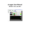
eLogger User Manual Version 1.2.0, July 2015 --------------------------------Written by Amber Hsieh Edited by Renee Lin Table of Contents 1. Introduction ................................................................. 5 1.1 Features............................................................................ 5 1.2 Supported Module ........................................................... 8 1.3 Installation ...................................................................... 10 2. The First Project ........................................................ 13 2.1 Create a New Project ..................................................... 13 2.2 Interface Introduction .................................................... 14 2.3 System Setting ............................................................... 14 2.4 Add Driver and Device................................................... 15 2.5 Add Tags ........................................................................ 17 2.6 Edit Page ........................................................................ 18 2.7 Edit Web Page ................................................................ 19 2.8 Data Log Configuration ................................................. 21 2.8.1 Remote Data Log Configuration.................................................... 21 2.8.2 Local Data Log Configuration ....................................................... 23 2.9 Run eLogger Runtime on PAC ...................................... 25 2.11 Upload the Web Pages from eLogger Developer ...... 27 3. Supported Driver ....................................................... 28 3.1 Module on Slot ............................................................... 28 3.2 Modbus TCP ................................................................... 31 3.3 Modbus Serial ................................................................ 36 4. Tag Mapping .............................................................. 40 4.1 Add new Tags ................................................................ 41 4.2 Edit Tag (batch edit supported) .................................... 42 4.3 Scaling ............................................................................ 43 4.4 Delete Tag ...................................................................... 43 5. Data Log ..................................................................... 44 5.1 Remote Data Log ........................................................... 44 5.2 Local Data Log ............................................................... 48 6. Layout Pages ............................................................. 50 6.1 Page Menu ...................................................................... 50 6.2 Design Page ................................................................... 51 6.3 Button Type .................................................................... 52 6.4 HMI Component Property .............................................. 53 7. Web Page ................................................................... 54 7.1 Web Page Menu ............................................................. 54 7.2 Design the Login Web Page .......................................... 55 7.2.1 Edit Login Web Page ...................................................................... 55 7.2.2 Component Introduction................................................................ 56 7.2.3 Property Directions ........................................................................ 56 7.3 Design HMI Web Page ................................................... 57 7.3.1 Edit the Web Page .......................................................................... 57 7.3.2 Component Introductions.............................................................. 58 7.3.3 Property Directions ........................................................................ 58 7.4 Upload Web Page .......................................................... 60 8. eLogger Runtime ....................................................... 61 8.1 eLogger Runtime Version ............................................. 61 8.2 eLogger Runtime Function ........................................... 62 Appendix A. Revisions ................................................. 63 1. Introduction eLogger is a free charge and easy-to-use software to implement HMI and data logger on Windows CE 5.0 based PACs (WinPAC and ViewPAC of ICP DAS), Windows CE 6.0 based PACs (XPAC-8000 of ICP DAS) and Windows Embedded Standard 2009 based PACs for simple I/O monitor and system control. It could reduce the cost and shorten the time to market. eLogger can develop a project with flexible I/O configuration quickly and easily. The setup can be completed in only 5 steps: configuring I/O modules, configuring data logger, designing HMI layout pages and web pages, uploading the project and web pages to PAC, executing the project. In these simple steps, there is no need of software programming knowledge. If more powerful functions needs to be added, eLogger also provides a flexible interface, “shared memory”, to cooperate with Visual Studio .NET and ISaGRAF programs. 1.1 Features 1.1.1 Supported PAC Developer:Windows 2K、Windows XP、Windows Vista、Windows7 Runtime target: Windows CE.NET 5.0 platform WinPAC series, ViewPAC series Windows CE.NET 6.0 platform XP-8000-CE6, XP-8000-Atom-CE6 Windows XPE platform XP-8000, XP-8000-Atom 1.1.2 Support Driver Math Curve(For Demo) Module on Slot Modbus Serial Master( Support Modbus RTU/Modbus ASCII) Modbus TCP master 1.1.3 HMI Components:Button、Text Box、Linear Gauge、Angular Gauge、LED、 Switch、Tank、Label、Plot、Seven Segment、Thermometer、Slider、Odometer Pages:Maximum of 32 pages. eLogger User Manual, Version 1.2.0 Last Revised: July 2015 Page:5 Copyright © 2015 ICP DAS Co., Ltd. All Rights Reserved. ★E-mail:[email protected]★ Web Pages Converter:Button、Text Box、Label、Seven Segment、Picture Toggle are supported. 1.1.4 Real Time Data Trend:Maximum of 5 trend line in one plot. 1.1.5 Value Scaling Set gain and offset can scale analog values from volt or amp unit to another physical unit. For example, rpm for rotation, kg for weight. 1.1.6 Account Management 3 levels operating management: Administrator, Power User, User Admin Power User User Open project Start/Stop project Set AO/DO values Switch group pages : allowed : not allowed 1.1.7 Remote Maintenance You can use eLogger Developer’s remote control function to Upload / Run / Stop the project through the Ethernet. 1.1.8 Database Local database: Supports csv format file. Remote database: Microsoft SQL Server 2005 or later. eLogger User Manual, Version 1.2.0 Last Revised: July 2015 Page:6 Copyright © 2015 ICP DAS Co., Ltd. All Rights Reserved. ★E-mail:[email protected]★ 1.1.9 Logic Control Programming Via the "Shared Memory", you can choose ISaGRAF or Visual Studio .Net to develop a logic control program and cooperate with the elogger. Your programs can access the data of I/O module and exchange other temporary data through the "Shared Memory". You can focus on the logic control programming. ISaGRAF (IEC61131-3 standard PLC languages) (Refer to ISaGRAF FAQ-115) Visual Studio .NET (C#, VB.NET) for Window CE.NET 5.0 eLogger User Manual, Version 1.2.0 Last Revised: July 2015 Page:7 Copyright © 2015 ICP DAS Co., Ltd. All Rights Reserved. ★E-mail:[email protected]★ 1.2 Supported Module Supported list: http://www.icpdas.com/products/PAC/winpac/io_support_list.htm 8K I/O Module 8K AI I8017HW 8K AO I8024W 8K DIO I8040W、I8041W、I8042W、I8046W、I8050W、I8051W、I8052W、 I8053W、I8054W、I8055W、I8056W、I8057W、I8058W、I8060W、 I8063W、I8064W、I8065W、I8066W、I8068W、I8069W、I8077W 87K I/O Module 87K AI I87005W、I87013W、I87015W、I87015PW、I87016W、I87017W、 I87017RW、I87017RCW、I87017DW、I87017ZW、I87017A5、I87018W、 I87018RW、I87018PW、I87018ZW、I87019RW、I87019PW、I87019ZW 87K AO I87024W、I87024CW、I87024DW、I87024RW、I87028CW 87K DIO I87037W、I87040W、I87040PW、I87041W、I87042W、I87046W、 I87051W、I87052W、I87053W、I87053PW、I87053WA2、I87053WA5、 I87053WAC1、I87053WE5、I87054W、I87055W、I87057W、I87057PW、 I87058W、I87059W、I87061W、I87063W、I87064W、I87065W、 I87066W、I87068W、I87069W、I87069PW ET-7000 ET-7005、ET-7015、ET-7016、ET-7017、ET-7017-10、ET-7018Z、ET-7019、 ET-7026、ET-7042、ET-7044、ET-7050、ET-7051、ET-7052、ET-7053、ET-7060、 ET-7065、ET-7066、ET-7067 PET-7000 PET-7005、PET-7015、PET-7016、PET-7017、PET-7017-10、PET-7018Z、 PET-7019、PET-7026、PET-7042、PET-7044、PET-7050、PET-7051、PET-7052、 PET-7053、PET-7060、PET-7065、PET-7066、PET-7067 WISE eLogger User Manual, Version 1.2.0 Last Revised: July 2015 Page:8 Copyright © 2015 ICP DAS Co., Ltd. All Rights Reserved. ★E-mail:[email protected]★ WISE-7105、WISE-7115、WISE-7117、WISE-7118Z、WISE-7119、WISE-7126、 WISE-7144、WISE-7151、WISE-7152、WISE-7160、WISE-7167 M-7000 AI M7005、M7015、M7016、M7016D、M7017、M7017C、M7017R、 M7017RC、M7018、M7018R、M7019R、M7033、M7033D AO M7022、M7024 DIO M7041、M7041D、M7045、M7045D、M7050、M7050D、M7051、 M7051D、M7052、M7052D、M7053、M7053D、M7055、M7055D、 M7059D、M7060、M7060D、M7067、M7067D eLogger User Manual, Version 1.2.0 Last Revised: July 2015 Page:9 Copyright © 2015 ICP DAS Co., Ltd. All Rights Reserved. ★E-mail:[email protected]★ 1.3 Installation Install .NET Framework 3.5 before eLogger is installed. The download link from Microsoft is Microsoft.com downloads. Execute eLogger setup to install eLogger Developer and eLogger Runtime. After the installation, there will be “eLogger Developer” and “eLogger Runtime” shortcut in “C:/Program Files/ICPDAS/eLogger”. eLogger Download Path The setup file name is eLoggersetup_vAAA_yyyymmdd.exe. AAA stands for version and yyyymmdd stands for release date. http://ftp.icpdas.com/pub/cd/winpac/napdos/elogger/setup/ 1.3.1 Step by step Step1. Download eloggersetup_vAAA_yyyymmdd.exe, and execute it. Step2. Choose the language interface and click OK. eLogger User Manual, Version 1.2.0 Last Revised: July 2015 Page:10 Copyright © 2015 ICP DAS Co., Ltd. All Rights Reserved. ★E-mail:[email protected]★ Step3. Click “Next” to continue installation. Step4. The default folder path is C:\ICPDAS\eLogger, the folder path can be changed by clicking “Browser”. Click” Next” to continue. eLogger User Manual, Version 1.2.0 Last Revised: July 2015 Page:11 Copyright © 2015 ICP DAS Co., Ltd. All Rights Reserved. ★E-mail:[email protected]★ Step5. Click “Install”. Step6. Click “Finish” to exit setup. eLogger User Manual, Version 1.2.0 Last Revised: July 2015 Page:12 Copyright © 2015 ICP DAS Co., Ltd. All Rights Reserved. ★E-mail:[email protected]★ 2. The First Project eLogger has two programs:eLogger Developer and eLogger Runtime. You can design the project with eLoggerDeveloper.exe on PC, and run the runtime file on PAC. You can follow the below steps to setup and run a project. Before starting a new project, the following items need to prepare. A VP-25W1 of ViewPAC series and an I-87041W module insert to the slot 0 of VP-25W1. 2.1 Create a New Project Step1. Execute the eLoggerDeveloper.exe, and click “Project”=>” New”, input the project name and click the Open button to create a new project. eLogger User Manual, Version 1.2.0 Last Revised: July 2015 Page:13 Copyright © 2015 ICP DAS Co., Ltd. All Rights Reserved. ★E-mail:[email protected]★ 2.2 Interface Introduction The left side of eLogger Developer main interface is the project function list, and the right side is the work area and property window. Property window Work area Project function list 2.3 System Setting Step1. Select System and set the Sampling Time to 1 second. eLogger User Manual, Version 1.2.0 Last Revised: July 2015 Page:14 Copyright © 2015 ICP DAS Co., Ltd. All Rights Reserved. ★E-mail:[email protected]★ 2.4 Add Driver and Device Step1. Select Driver, and select a driver “ModuleOnSlot”, then click “Next”. Step2. Click “Install” to add the driver to the project. Step3. Select “Module on Slot” and click the “Add Device” button in the DriverForm to add a new device. eLogger User Manual, Version 1.2.0 Last Revised: July 2015 Page:15 Copyright © 2015 ICP DAS Co., Ltd. All Rights Reserved. ★E-mail:[email protected]★ Step4. Set module from Module drop-down list to I-87041W, and set Device Name and Slot. Click the “Add” button to add the module to the driver. eLogger User Manual, Version 1.2.0 Last Revised: July 2015 Page:16 Copyright © 2015 ICP DAS Co., Ltd. All Rights Reserved. ★E-mail:[email protected]★ 2.5 Add Tags Step1. Expand Tag Mapping and select “DO Tag”, the memory mapping will show in the right side. The device, “I87041W”, uses memory address from 0 to 31 of CoilStatus in the Shared Memory to save its values. Step2. Click “New Tag” to add 5 tags. These tags will be used to connect with HMI components and the Shared Memory. Step3. Select the rows of the tag list, and set the Memory Address to 0. The Memory Address of DO0 will be set to 0, and DO1 will be 1. Now these 5 tags (DO0 to DO4) point to CoilStatus [0] to [4]. eLogger User Manual, Version 1.2.0 Last Revised: July 2015 Page:17 Copyright © 2015 ICP DAS Co., Ltd. All Rights Reserved. ★E-mail:[email protected]★ 2.6 Edit Page Step1. Expand Page and select “Page0” to open HMI layout page. Select the Switch component on the toolbar and add components to the page by dragging and dropping. Step2. Select each of Switches, and then set the Tag Type to DO Tag and set Tag Name to DO0 to DO3 in the property window. Step3. Click the Button component on the toolbar and add two components by dragging and dropping to the page. Select one of the buttons and set its Button Type to “Run” and the other to “Exit”. eLogger User Manual, Version 1.2.0 Last Revised: July 2015 Page:18 Copyright © 2015 ICP DAS Co., Ltd. All Rights Reserved. ★E-mail:[email protected]★ 2.7 Edit Web Page Step1. Select the Web Page to open the web page configuration window. Click “New” to create a web page. The newly created web page name is assigned to index1 by eLogger. Step2. Set the username and password of web pages. The default settings are “admin” and “0000”. Step3. Select “login” to edit the login web page. Select the text box component and set its Password property to True so that the password text box will show as password format. eLogger User Manual, Version 1.2.0 Last Revised: July 2015 Page:19 Copyright © 2015 ICP DAS Co., Ltd. All Rights Reserved. ★E-mail:[email protected]★ Step4. Select “index1” of the Web Page to edit the web page. Add 2 Picture Toggle components by dragging it to the web page. Select each of components and set its property. The Tag Type set to DO Tag and Tag Name set to DO0 and DO1. Step5. Add a Button component to the web page and set its Button Type to LogOut. eLogger User Manual, Version 1.2.0 Last Revised: July 2015 Page:20 Copyright © 2015 ICP DAS Co., Ltd. All Rights Reserved. ★E-mail:[email protected]★ 2.8 Data Log Configuration 2.8.1 Remote Data Log Configuration Step1. Unfold the Procedure and select RemoteDataLog to open configured window. Step2. Click the checkbox to enable the RemoteDataLog. Step3. Input the IP address to Server IP text field. 192.168.2.191,1433 is input in this case. 1433 stands for TCP connect port to SQL Server. Input username and password to User Name and User Password text field. Input the scan rate to Scan Interval text field. The default value for Scan Interval is 60 seconds. The Database Name text field is to set the name of the database. DODatabase is input in this case. Both of database path and backup path are required. Step4. Click Server Connectivity Check to confirm the connection and account information. eLogger User Manual, Version 1.2.0 Last Revised: July 2015 Page:21 Copyright © 2015 ICP DAS Co., Ltd. All Rights Reserved. ★E-mail:[email protected]★ If the IP address, username and password are correct, a message will show as below. Step5. Click New and input a table name, Station1 in this case, in the database, and click OK to create table. Step6. In the Column List, select DO Tags from drop-down list and select the tag name which will be recorded, DO0, DO1, DO2 and DO3 are selected in this case. Click Add New Column and the selected tags will be added to the column list. eLogger User Manual, Version 1.2.0 Last Revised: July 2015 Page:22 Copyright © 2015 ICP DAS Co., Ltd. All Rights Reserved. ★E-mail:[email protected]★ 2.8.2 Local Data Log Configuration Step1. Unfold the Procedure and select LocalDataLog to open configured window. Step2. Click the checkbox to enable the LocalDataLog. Step3. Click New and input the record file name, Station1 in this case, in the Edit Name window. Click OK to create the file. eLogger User Manual, Version 1.2.0 Last Revised: July 2015 Page:23 Copyright © 2015 ICP DAS Co., Ltd. All Rights Reserved. ★E-mail:[email protected]★ Step4. Select DO Tags from drop-down list and select the tag name which will be recorded, DO0, DO1, DO2 and DO3 are selected in this case. Click Add Header and the selected tags will be added to the record list. eLogger User Manual, Version 1.2.0 Last Revised: July 2015 Page:24 Copyright © 2015 ICP DAS Co., Ltd. All Rights Reserved. ★E-mail:[email protected]★ 2.9 Run eLogger Runtime on PAC Step1. Copy the runtime files to PAC. For_WinPAC is copied to VP-25W1 in the case. For_WinPAC supports WinPAC series, ViewPAC series. For_XP8000CE6 supports XP-8000-Atom-CE6. For_XP8000WES supports XP-8000-Atom. Step2. On PAC, copy all the files (base, WebBase) in the copy_to_www_root folder to HTTP www root. For WinPAC and XP8000CE6, copy the files in copy_to_system_disk folder to the \System_Disk. For XP8000WES, copy the files in copy_to_windows folder to the C:\Windows. Step3. Execute RuntimeXXXX.exe. RuntimeWinPacCE5 is executed in this case. eLogger User Manual, Version 1.2.0 Last Revised: July 2015 Page:25 Copyright © 2015 ICP DAS Co., Ltd. All Rights Reserved. ★E-mail:[email protected]★ 2.10 Upload the Project from eLogger Developer Step1. Click eLogger Developer’s “Project” => “Remote Machine” to open RemoteMachine window. Step2. Input the PAC’s IP address, and then click “Upload Project”. Step3. After the runtime program received the project, click “Run” in the RemoteMachine to run the project. The received message in the runtime program shows as below. eLogger User Manual, Version 1.2.0 Last Revised: July 2015 Page:26 Copyright © 2015 ICP DAS Co., Ltd. All Rights Reserved. ★E-mail:[email protected]★ 2.11 Upload the Web Pages from eLogger Developer Step1. Click eLogger Developer’s “Project” => “Remote Machine” to open the RemoteMachine window. Step2. Input the PAC’s IP address, and then click “Upload Web Pages”. The web files and pictures (jpg, jpeg, png, gif and bmp picture files are all included) in the CE5Web, CE6Web or XPEWeb will be uploaded to the PAC. Step3. When web pages upload finished, message in the runtime program will show as below. Step4. Open the web browser and input the IP address of the PAC, for example, http://192.168.2.195/, and then you can browse the web page. eLogger User Manual, Version 1.2.0 Last Revised: July 2015 Page:27 Copyright © 2015 ICP DAS Co., Ltd. All Rights Reserved. ★E-mail:[email protected]★ 3. Supported Driver eLogger driver communicate with the I/O modules, and save the I/O values to the Shared Memory. Here are the eLogger supported driver lists, and the chapter will show you how to setup the driver. Module on Slot Modbus TCP Modbus Serial 3.1 Module on Slot This driver supports the I-8K, I-87K module on PAC’s slot. Step1. Select the Driver in the function list and select the ModuleOnSlot from the Driver drop-down menu, and then click “Next”. Step2. Click “Install” to go on next step. eLogger User Manual, Version 1.2.0 Last Revised: July 2015 Page:28 Copyright © 2015 ICP DAS Co., Ltd. All Rights Reserved. ★E-mail:[email protected]★ Step3. Select the ModuleOnSlot in the function list to open the DriverForm window. Click “Add Device” to add a device to the driver. Step4. Select a module from drop-down menu, and select the slot number, and then click “Add”. The device and it’s channels will be showed on the list. eLogger User Manual, Version 1.2.0 Last Revised: July 2015 Page:29 Copyright © 2015 ICP DAS Co., Ltd. All Rights Reserved. ★E-mail:[email protected]★ Step5. Select the channel and edit the channel’s note. The channels will map to the shared memory. You can see them on “Tag Mapping”. eLogger User Manual, Version 1.2.0 Last Revised: July 2015 Page:30 Copyright © 2015 ICP DAS Co., Ltd. All Rights Reserved. ★E-mail:[email protected]★ 3.2 Modbus TCP This driver supports Modbus TCP modules of ICPDAS, and standard Modbus TCP devices. The driver uses Modbus command: FC1 Read multiple coils status (0xxxx) for DO FC2 Read multiple input discrete (1xxxx) for DI FC3 Read multiple registers (4xxxx) for AO FC4 Read multiple input registers (3xxxx) for AI FC5 Write single coil (0xxxx) for DO FC6 Write single register (4xxxx) for AO Step1. Select the Driver in the function list and select the ModbusTcp from the Driver drop-down menu, and then click “Next”. Step2. Click “Install” to go on next step. eLogger User Manual, Version 1.2.0 Last Revised: July 2015 Page:31 Copyright © 2015 ICP DAS Co., Ltd. All Rights Reserved. ★E-mail:[email protected]★ Step3. Select the ModbusTcp in the function list to open the setting window. Click “Add IP” to create a tcp connection for each IP address. Step4. In the IP Setting window, input the IP address and click “OK”, and then it will show on the list. Step5. Click “Add Device” to add a device. eLogger User Manual, Version 1.2.0 Last Revised: July 2015 Page:32 Copyright © 2015 ICP DAS Co., Ltd. All Rights Reserved. ★E-mail:[email protected]★ Step6. Select a connection IP, and input a device name for identification, and then set the device’s station address, which refers to slave ID or station ID. And then click “Add Register”. Step7. Select a module and the register will be filled automatically, and then click “OK”. eLogger User Manual, Version 1.2.0 Last Revised: July 2015 Page:33 Copyright © 2015 ICP DAS Co., Ltd. All Rights Reserved. ★E-mail:[email protected]★ If the module isn’t in the list, select “Enter Number” for filling the registers manually. Step8. After the registers were added, click “Add” to add the device. eLogger User Manual, Version 1.2.0 Last Revised: July 2015 Page:34 Copyright © 2015 ICP DAS Co., Ltd. All Rights Reserved. ★E-mail:[email protected]★ Step9. Select the channel and edit the channel’s note. The channels will map to the shared memory. You can see them on “Tag Mapping”. eLogger User Manual, Version 1.2.0 Last Revised: July 2015 Page:35 Copyright © 2015 ICP DAS Co., Ltd. All Rights Reserved. ★E-mail:[email protected]★ 3.3 Modbus Serial This driver supports Modbus RTU modules of ICPDAS, and standard Modbus RTU/ASCII devices. The driver uses Modbus command: FC1 Read multiple coils status (0xxxx) for DO FC2 Read multiple input discrete (1xxxx) for DI FC3 Read multiple registers (4xxxx) for AO FC4 Read multiple input registers (3xxxx) for AI FC5 Write single coil (0xxxx) for DO FC6 Write single register (4xxxx) for AO Step1. Select the Driver in the function list and select the ModbusSerial from the Driver drop-down menu, and then click “Next”. Step2. Click “Install” to go on next step. eLogger User Manual, Version 1.2.0 Last Revised: July 2015 Page:36 Copyright © 2015 ICP DAS Co., Ltd. All Rights Reserved. ★E-mail:[email protected]★ Step3. Select the ModbusSerial in the function list to open the setting window. Click “Add” to create a COM port connection to connect the Modbus serial devices. Step4. Click the “Add Device” to add a new device. Step5. Select a connection COM port, input a name for identification, and set the device’s ID (equals to ID address, station ID, or address).And then click “Add Register”. eLogger User Manual, Version 1.2.0 Last Revised: July 2015 Page:37 Copyright © 2015 ICP DAS Co., Ltd. All Rights Reserved. ★E-mail:[email protected]★ Step6. Select a module, and the register will be filled automatically. If the module isn’t in the list, select “Enter Number” for filling the registers manually. eLogger User Manual, Version 1.2.0 Last Revised: July 2015 Page:38 Copyright © 2015 ICP DAS Co., Ltd. All Rights Reserved. ★E-mail:[email protected]★ Step7. After the registers were added, click “Add” to add the device. Step8. Select the channel and edit the channel’s note. The channels will map to the shared memory. You can see them on “Tag Mapping”. eLogger User Manual, Version 1.2.0 Last Revised: July 2015 Page:39 Copyright © 2015 ICP DAS Co., Ltd. All Rights Reserved. ★E-mail:[email protected]★ 4. Tag Mapping The Tag Mapping lists channels of all devices added in the project, and automatically arrays them by Shared Memory addresses sequentially. You can add new tags assigned special Shared Memory addresses, and set the properties in need. The following description will show you how to set Tag property. Shared Memory address starts from “0”. eLogger User Manual, Version 1.2.0 Last Revised: July 2015 Page:40 Copyright © 2015 ICP DAS Co., Ltd. All Rights Reserved. ★E-mail:[email protected]★ 4.1 Add new Tags Step1 Step2 Step4 Step3 Step1. Select the Tag list. Step2. Click “New Tag” -> input the number of new tags -> “OK”. Step3. Select Tag. (You also can drag to select all tags with left mouse button.) Step4. Input the Shared Memory address in the Memory Address text box. eLogger User Manual, Version 1.2.0 Last Revised: July 2015 Page:41 Copyright © 2015 ICP DAS Co., Ltd. All Rights Reserved. ★E-mail:[email protected]★ 4.2 Edit Tag (batch edit supported) Tag Name: You can specify a name easy to identify. Description: You can edit the tag’s description. Data Type: Select the input/output type of channel. Data Type Shared Memory address use 16-bit Signed Integer 1 16-bit Unsigned Integer 1 32-bit Signed Long 2 32-bit Unsigned Long 2 32-bit Float 2 Gain, Offset: Set gain and offset can scale the memory value to another physical unit. To obtain these two values first find out two sets of value and do operation by the formula provided below.(Example: display the temperature -270~270) eLogger User Manual, Version 1.2.0 Last Revised: July 2015 Page:42 Copyright © 2015 ICP DAS Co., Ltd. All Rights Reserved. ★E-mail:[email protected]★ 4.3 Scaling The scaling tool helps you automatically get the “Gain” value and “Offset” value. Press the “Scaling” button, select the “Channel Type” you need, and then press the “OK” button. 4.4 Delete Tag Step3 Step2 Step1. Select the Tag to delete eLogger User Manual, Version 1.2.0 Last Revised: July 2015 Page:43 Copyright © 2015 ICP DAS Co., Ltd. All Rights Reserved. ★E-mail:[email protected]★ 5. Data Log 5.1 Remote Data Log The RemoteDataLog can transfer I/O data to the Microsoft SQL Server in PC. The version of Microsoft SQL Server is 2005 or later. To query the data of SQL Server, besides login to SQL Server and send SQL command to get data, you can use a web page that generated by eLogger to query the SQL Server. Step1. Unfold the Procedure and select RemoteDataLog to open configured window. Step2. Click the checkbox to enable the RemoteDataLog. Step3. Input the IP address to Server IP text field. Input username and password to User Name and User Password text field. Input the scan rate to Scan Interval text field. The default value for Scan Interval is 60 seconds. The Database Name text field is to set the name of the database. Both of database path and backup path are required. eLogger User Manual, Version 1.2.0 Last Revised: July 2015 Page:44 Copyright © 2015 ICP DAS Co., Ltd. All Rights Reserved. ★E-mail:[email protected]★ Step4. Click Server Connectivity Check to confirm the connection and account information. If the IP address, username and password are correct, a message will show as below. If the IP address, username and password are correct, but the database name already exists, a message will show as below. If the username or password is incorrect, a message will show as below. eLogger User Manual, Version 1.2.0 Last Revised: July 2015 Page:45 Copyright © 2015 ICP DAS Co., Ltd. All Rights Reserved. ★E-mail:[email protected]★ Step5. Click New and input a table name in the database, and click OK to create table. Step6. In the Column List, select DO Tags from drop-down list and select the tag name which will be recorded. Click Add New Column and the selected tags will be added to the column list. Step7. To query the data in the SQL Server, click “Test SQL on Web” and eLogger will create a web page named xxx.asp and use the account information to login. Xxx stands for the database name. eLogger User Manual, Version 1.2.0 Last Revised: July 2015 Page:46 Copyright © 2015 ICP DAS Co., Ltd. All Rights Reserved. ★E-mail:[email protected]★ The web page will opened by the default browser, and list all tables in the database. Set the Start Date, End Date and table, and then click Search. The result will show on the web page. Click Save file can save the result as a csv format file. eLogger User Manual, Version 1.2.0 Last Revised: July 2015 Page:47 Copyright © 2015 ICP DAS Co., Ltd. All Rights Reserved. ★E-mail:[email protected]★ 5.2 Local Data Log The I/O data can be recorded to the storage device of PAC, such as SD memory card. The file is saved as csv format, and the file can be opened by Microsoft Access or Microsoft Excel. Step1. Unfold the Procedure and select LocalDataLog to open configured window. Step2. Click the checkbox to enable the LocalDataLog. Step3. Click New and input the record file name in the Edit Name window. Click OK to set the record file name. eLogger User Manual, Version 1.2.0 Last Revised: July 2015 Page:48 Copyright © 2015 ICP DAS Co., Ltd. All Rights Reserved. ★E-mail:[email protected]★ Step4. Select DO Tags from drop-down list and select the tag name which will be recorded. Click Add Header and the selected tags will be added to the record list. eLogger User Manual, Version 1.2.0 Last Revised: July 2015 Page:49 Copyright © 2015 ICP DAS Co., Ltd. All Rights Reserved. ★E-mail:[email protected]★ 6. Layout Pages 6.1 Page Menu Input a page name and Click NEW List all the page names automatically New: Add a new page to design. Rename: Select an exist page, and click “Rename”, and then enter new name. Remove: Select an exist page, and click “Remove”. Import: Import page file. Export: Export page file. eLogger User Manual, Version 1.2.0 Last Revised: July 2015 Page:50 Copyright © 2015 ICP DAS Co., Ltd. All Rights Reserved. ★E-mail:[email protected]★ 6.2 Design Page Step3 Step2 Step4 Step1 Step5 Step1. Select a page to edit. Step2. The default page size is 640x480, you can change size by “Layout Size”. Step3. The background picture can be set by selecting “Background Picture” from the menu. It will open the default folder named Pic, select a picture file and click “open” to set as back picture. If the picture doesn’t exist in the Pic folder, program will automatically duplicate the picture to the Pic folder. Step4. In the component list, add a proper component into the page by “click” the component and drag it on the layout. Step5. Select the object and set its property (select “Tag Type” -> select “Tag Name”). eLogger User Manual, Version 1.2.0 Last Revised: July 2015 Page:51 Copyright © 2015 ICP DAS Co., Ltd. All Rights Reserved. ★E-mail:[email protected]★ 6.3 Button Type Button Type Description Run “Start” and “Stop” project. Simulation Simulation value. SwitchPage Switch to the page, you have to assign the page name. Exit Return to eLogger Runtime menu. LogIn Enter password to log in as “power user” or “Admin”. eLogger User Manual, Version 1.2.0 Last Revised: July 2015 Page:52 Copyright © 2015 ICP DAS Co., Ltd. All Rights Reserved. ★E-mail:[email protected]★ 6.4 HMI Component Property Property Name Description MouseControl Enable or disable the mouse control to set output Decimal Decimal number Unit The unit string will be added after the value ColorSection A color range from start to stop (Gauge) GaugeAngle The gauge angle is start with GaugeAngleMin, and the span is the GaugeAngleSpan Scale The value will be displayed from minimum to maximum. Show_Sign Show the sign on the left DigitalNumber The total length of the number (NumberLED) TestValue Input the value to test the display BackColor Background color Fore_Color The font color ConformWindow Popup window to confirm DO output. DisplayText Specifies the text displayed on the indicator FontStyle The font size and font face. LedStyle Specifies the indicator style OffColor、 The color when DI/O value is false or true OnColor OffDisplatText、 Specifies the text on the indicator when DI/O value is off or on OnDisplatText OffTextColor、 The color of the text when DI/O value is false or true OnTextColor eLogger User Manual, Version 1.2.0 Last Revised: July 2015 Page:53 Copyright © 2015 ICP DAS Co., Ltd. All Rights Reserved. ★E-mail:[email protected]★ 7. Web Page 7.1 Web Page Menu Input a web page name and Click NEW List all the web page automatically Web Page Username: The username to login the web page. Default value is “admin”. Web Page Password: The password to login the web page. Default value is “0000”. New: Add a new web page to design. Rename: Select an exist web page, and click “Rename”, and then enter new name. Remove: Select an exist web page, and click “Remove”. Import: Import web page file. The default folder to open is MyWebPage. Export: Export web page file. The default folder to save is MyWebPage. eLogger User Manual, Version 1.2.0 Last Revised: July 2015 Page:54 Copyright © 2015 ICP DAS Co., Ltd. All Rights Reserved. ★E-mail:[email protected]★ 7.2 Design the Login Web Page 7.2.1 Edit Login Web Page Step2 Step3 Step1 Step4 Step1. Select the login page to edit. Step2. The background picture can be set by selecting “Back Picture” from the menu. It will open the default folder named WebBackPic, select a picture file and click “open” to set as back picture. If the picture doesn’t exist in the WebBackPic folder, program will automatically duplicate the picture to the WebBackPic folder. Step3. The components as shown above are default in the Login web page. In the login web page, it is not allow to delete, cut, paste or copy but can set property of the components. If select the form, you can set the background color of the web page. Step4. Select a component and set its property (select “Tag Type” -> select “Tag Name”). eLogger User Manual, Version 1.2.0 Last Revised: July 2015 Page:55 Copyright © 2015 ICP DAS Co., Ltd. All Rights Reserved. ★E-mail:[email protected]★ 7.2.2 Component Introduction Name Icon Description Label The text displayed on label. Text Box The input text box. The username or password is set to input to this text box. Button The button that use to log in the web page. The button type: LogIn is only applicable is the login web page. 7.2.3 Property Directions Property Name Description Back Color Set the background color of the web page DisplayText Specifies the text displayed on the indicator FontStyle The font size and font face. Fore_Color The color of the font or value. Password Set the text if it is shown as the password form. Set to True to display as the password form in the web page. (The Password property only use in the login web page.) eLogger User Manual, Version 1.2.0 Last Revised: July 2015 Page:56 Copyright © 2015 ICP DAS Co., Ltd. All Rights Reserved. ★E-mail:[email protected]★ 7.3 Design HMI Web Page 7.3.1 Edit the Web Page Step2 Step5 Step3 Step1 Step6 Step4 Step1. Select a web page to edit. Step2. The background picture can be set by selecting “Background Picture” from the menu. It will open the default folder named WebBackPic, select a picture file and click “open” to set as back picture. If the picture doesn’t exist in the WebBackPic folder, program will automatically duplicate the picture to the WebBackPic folder. Step3. Select a HMI component, and add it to the web page. Step4. Select a component and its property will be showed. If select the form, you can set the background color of the web page. Step5. Select a component and set its property. eLogger User Manual, Version 1.2.0 Last Revised: July 2015 Page:57 Copyright © 2015 ICP DAS Co., Ltd. All Rights Reserved. ★E-mail:[email protected]★ Step6. Select a component and right-clicked the mouse can do cut, copy, paste and delete to the component. 7.3.2 Component Introductions Name Icon Description Text Box To read or write register value. Seven Segment To read or write register value. Label The text display on label. Button type: SwitchPage、LogOut Button To switch page or logout. To display different picture when DI or DO status Picture Toggle changed. 7.3.3 Property Directions Tag Property Name Description Tag Type The tag type depends on the selected tag. Tag Name The name of the tag. The description of the tag. Tag Description (The tag properties are read-only in this stage and can be edited in 4.2 Edit Tag) Output Limit The maximum and minimum value of the output range. If the AO value exceed the range, it won’t do output. Memory Tag Address Type, Address, Data Type, Gain, Offset and Range (The tag properties are read-only in this stage and can be eLogger User Manual, Version 1.2.0 Last Revised: July 2015 Page:58 Copyright © 2015 ICP DAS Co., Ltd. All Rights Reserved. ★E-mail:[email protected]★ Property edited in 4.2 Edit Tag) HMI Component Property Name Description Back Color Set the background color of the web page Back_Color Set the background color of the component Decimal Decimal number DigitalNumber The total length of the number (NumberLED) DisplayText Specifies the text displayed on the indicator FontStyle The font size and font face. Fore_Color The color of the font or value. MouseControl Enable or disable the mouse control to set output OffPicture Display the specific picture when digital status is off.(Note) OnPicture Display the specific picture when digital status is on. (Note) Show_Sign Show the sign on the left TestValue Input the value to test the display Unit The unit string will be added after the value ValueTest Do value test to Picture Toggle component Note The picture is selected from the default folder named WebPic. If the picture doesn’t exist in the folder, the picture will be duplicated to the WebPic folder. eLogger User Manual, Version 1.2.0 Last Revised: July 2015 Page:59 Copyright © 2015 ICP DAS Co., Ltd. All Rights Reserved. ★E-mail:[email protected]★ 7.4 Upload Web Page Step1. Select Remote Machine form the menu. Step2. Input the IP address of the PAC and click “Upload Web Page”. All the web files in the folder (CE5Web, CE6Web or XPE Web) and pictures (support jpg, jpeg, png, gif and bmp picture files) will be uploaded to the PAC. eLogger User Manual, Version 1.2.0 Last Revised: July 2015 Page:60 Copyright © 2015 ICP DAS Co., Ltd. All Rights Reserved. ★E-mail:[email protected]★ 8. eLogger Runtime 8.1 eLogger Runtime Version Before start up a project in the eLogger Runtime, the Runtime folder needs to be copied to the PAC via Ethernet or USB. The location of Runtime folder is depended on the installation. For example, copy the For_WinPAC folder at the location “C:\ICPDAS\eLogger\eLogger_Runtime” to VP-25W1. Version Supported ICP DAS PAC WP-8131、WP-8431、WP-8831 WP-8137、WP-8437、WP-8837 For_WinPAC WP-8141、WP-8441、WP-8841 WP-8147、WP-8447、WP-8847 VP-23W1、VP-25W1 XP-8041-CE6、XP-8341-CE6、XP-8741-CE6、 XP-8047-CE6、XP-8347-CE6、XP-8747-CE6、 For_XP8000CE6 XP-8049-CE6、XP-8349-CE6、XP-8749-CE6、 XP-8046-CE6、XP-8346-CE6、XP-8746-CE6、 For_XP8000WES XP-8041、XP-8341、XP-8741 When copy is done, all the files in the copy_to_www_root folder need to copy to HTTP www root, and the files in the copy_to_system_disk folder needs to copy to \System_Disk (For_XP8000WES version: copy the files in copy_to_windows folder to C:\Windows). eLogger User Manual, Version 1.2.0 Last Revised: July 2015 Page:61 Copyright © 2015 ICP DAS Co., Ltd. All Rights Reserved. ★E-mail:[email protected]★ 8.2 eLogger Runtime Function Message box Function Description Execute Project Start to run the project Open Project Open the project and you can select a project to execute. Log In Enter the password to log in as “power user” or “admin” Log Out User log out Auto Run When start up the eLogger Runtime program, the project that showed in message box will run automatically if “Auto Run” is checked. Message Box Indicate the user’s authority, project location and the project name. Furthermore, display the status of receiving a project or web pages. eLogger User Manual, Version 1.2.0 Last Revised: July 2015 Page:62 Copyright © 2015 ICP DAS Co., Ltd. All Rights Reserved. ★E-mail:[email protected]★ Appendix A. Revisions Version Date Amendments 1.1.0 2014/8/21 Add 7. Web Pages 1.2.0 2015/7/13 Add 5. Data Log. Revise 2. The First Project eLogger User Manual, Version 1.2.0 Last Revised: July 2015 Page:63 Copyright © 2015 ICP DAS Co., Ltd. All Rights Reserved. ★E-mail:[email protected]★