1
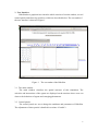
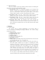
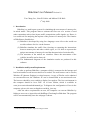
BikeSim User Manual Version 1.0
Tzu-Chang Lee*, John W. Polak* and Michael G.H. Bell*
1st July 2008
1 Introduction
BikeSim is a multi-agent system for simulating the movements of motorcycles
in mixed traffic. This program aims to estimate the flow rate of a section of road
under constraints such as lane layout, traffic composition, traffic signals, etc. Hence, it
is a useful tool for analysing the impacts of the presence of motorcycles. The features
of BikeSim are listed below:
(1) BikeSim is developed by using Java language: users all over the world can
use this software for free via the Internet.
(2) BikeSim simulates the traffic flow focusing on capturing the interactions
between motorcycles and other vehicle types, so it is able to represent the
unique movements of motorcycles and the characteristics of mixed traffic.
(3) The outcomes of the models are visualises. Hence the movements of the
vehicles in traffic can be observed.
(4) The fundamental diagrams of the simulation results are produced in this
software.
2 Installation and System Requirements
In order to perform BikeSim, a computer which is connected to the Internet and
has been installed a web browser and Java is needed. The web browser can be Firefox,
Windows IE (Internet Explorer) or other browsers. A copy of Firefox can be obtained
at www.mozilla.com; the Windows IE can be downloaded at www.microsoft.com.
The browser should be set to enable to display Java applets. The Java environment in
the computer should be Java J2SE 1.4 or later edition, which is available at
www.java.com/en/download/manual.jsp. To diagnose the configuration of Java in the
computer, please visit www.realapplets.com/help_java.asp.
After the above requirements are met, the computer can execute BikeSim by
linking to www.cts.cv.imperial.ac.uk/StaffPages/TzuchangLee/Bike.htm. The program
will be run automatically once the webpage is shown.
*
Centre for Transport Studies, Imperial College London
1
3 User Interface
BikeSim has a graphical user interface which consists of a main window, several
control panels and observing windows, which are described below. The screenshot of
the user interface is shown in Figure 1.
Figure 1
The screenshot of the BikeSim.
3.1 The main window
The main window visualises the spatial structure of this simulation. The
activities and interactions of the agents are displayed on the monitor where users can
observe the behaviour of agents and emerging phenomena.
3.2 Control panels:
The control panels are set to change the attributes and parameters of BikeSim.
The adjustment of these panels is detailed in sections 4.2 and 4.3.
2
3.3 Observing windows:
There are a number of observing windows with the function of collecting the
information of the agents and displaying the graphs.
(1) Speed-Density Chart: The fundamental diagrams can be obtained from
BikeSim. To display the speed-density relationship of the simulation result,
press the ‘Control Panels’ button from the main window. In the pop-up
window ‘Main Controller’, press the ’Speed-Density Chart’ button.
(2) Speed-Flow Chart: Press the ‘Control Panels’ button from the main
window; then press the ‘Speed-Flow Chart’ from the ‘Main Controller’.
(3) Flow-Density Chart: Press the ‘Control Panels’ button from the main
window; then press the ‘Flow-Density Chart’ from the ‘Main Controller’.
(4) Saturation Flow Chart: The Saturation Flow Chart describes the
relationship of the flow rate and time measured at the end of the traffic. It is
able to illustrate the saturation flow rate of the traffic when the traffic signal
has turned on.
4 Simulation
4.1 Default settings
The program will be executed automatically as the browser links to
www.cts.cv.imperial.ac.uk/StaffPages/TzuchangLee/Bike.htm. The default settings
are described as follows:
(1)
(2)
(3)
(4)
(5)
(6)
Simulation time: 12,000 sec.
Length of the link: 300 m.
Number of lanes: 3.
Proportion of motorcycles: 25%.
Speed limit: 48 km/hr.
Width of lanes: The widths of these lanes from the fast lane to the slow lane
(for left-hand traffic) are 3.2 m, 3.2 m and 3.6 m.
(7) Signal control: A traffic signal is scheduled to take effect at the 1,801th sec.
This traffic signal, employed for the purpose of simulating the traffic
disturbance downstream, is installed near the end of the link. It is designed
to have three signal phases with a cycle length of 93 sec. The length of the
amber light is set to be the first 3 sec of the red light. In order to simulate the
traffic conditions from slightly delay to the traffic gridlock, the lengths of
the green and red lights varied with the simulation time. The length the red
light (including the amber) was 0 sec initially, but would increase by 1 sec
for every 200 sec. This schedule ensured that this simulation was able to
represent all kinds of flow-speed-density compositions in the traffic.
3
Signal
3.6 m
3.2 m
3.2 m
290 m
Figure 2
10 m
The default settings of the simulation environment
(8) Vehicle generation: The vehicles in each lane are generated by the time
headways drawn from a normal distribution, normal(2000/(200+t),0.52) sec.
The mean of this normal distribution decreased along with the simulation
time, t, following a rectangular hyperbola curve. However, when the time
headways drawn form this distribution were shorter than safety time
headways, the vehicles would be generated by safety time headways. Thus,
this vehicle generation mechanism could simulate the traffic which changed
gradually from a free flow to a congested flow. The flow would achieve the
maximum flow rate at the simulation time of around 1,800 sec.
(9) Other settings: The description of the other settings in BikeSim can be
found in chapter 7 of (1).
4.2 Simulator control
(1) Start: Start the simulation according to the current settings. The ‘Start’
button is located at the main window.
(2) Stop: Stop the simulation according to the current settings. The ‘Stop’ button
is located at the main window.
(3) Clear: Redraw the images according to the current simulation results. The
‘Clear’ button is located at the main window.
(4) Reset: Reset the parameters of the simulation according to the adjustments
of users. The ‘Reset’ button is located at the main window.
(5) Window scope: BikeSim is able to zoom out or zoom in on the traffic by
changing the scope of the window. This can be done by pressing the ‘Control
Panels’ button from the main window. In the pop-up window ‘Main
Controller’, press the ‘Road’ button; then change the value of ‘Window
scope’ in the window ‘Road Property’. Please note that the ‘Reset’ button in
the main window has to be pressed to confirm the change.
(6) Computational speed: BikeSim is able to adjust the computational speed of
the program. A slower speed enables users to observe the movement of the
vehicles, whereas a faster one saves the simulating time. To change the
4
speed, press the ‘Control Panels’ button from the main window. In the
pop-up window ‘Parameter Controller’, press the ‘Parameter’ button; then
change the value of ‘Time Warp Factor’ by adjust the slider bar. The larger
value means the faster executing speed. The default value is 30. After the
adjustment, press ‘Reset’ button in the main window to confirm the change.
4.3 Scenario settings
(1) Length of the link: To change the length of the link, press the ‘Control
Panels’ button from the main window. In the pop-up window ‘Main
Controller’, press the ‘Road’ button; then change the value of ‘Street Length’
in the window ‘Road Property’. After the adjustment, press ‘Reset’ button in
the main window to confirm the change.
(2) Width of the lanes: To change the width of the lanes, press the ‘Control
Panels’ button from the main window. In the pop-up window ‘Main
Controller’, press the ‘Road’ button; then change the value of ‘Width of
Lane x’ for each lane in the window ‘Road Property’. After the adjustment,
press ‘Reset’ button in the main window to confirm the change.
(3) Traffic signal: To turn on or turn off the traffic signal, press the ‘Control
Panels’ button from the main window. In the pop-up window ‘Main
Controller’, press the ‘Simulation’ button; then select or un-select ‘Signal’ in
the window ‘Simulation Controller’. After the adjustment, press ‘Reset’
button in the main window to confirm the change.
(4) Advanced stop line: BikeSim is able to simulate the advanced stop line,
which is used to constitute a reservoir area for motorcycles behind the traffic
signal. The advanced stop line is set to be situated 10 m back from the
primary stop line. It is synchronised with the traffic signal and forbids
passenger cars to run across in the red time. To activate the advanced stop
line, press the ‘Control Panels’ button from the main window. In the pop-up
window ‘Main Controller’, press the ‘Simulation’ button; then select
‘Advanced Stop Line’ in the window ‘Simulation Controller’. After the
adjustment, press ‘Reset’ button in the main window to confirm the change.
(5) Motorcycle desired speed: To change the desired speed of motorcycles,
press the ‘Control Panels’ button from the main window. In the pop-up
window ‘Parameter Controller’, press the ‘Parameter’ button; then change
the value of ‘Bike Desired Speed’ by adjust the slider bar. The default value
is 48 km/hr. After the adjustment, press ‘Reset’ button in the main window to
confirm the change.
(6) Passenger car desired speed: To change the desired speed of passenger cars,
5
press the ‘Control Panels’ button from the main window. In the pop-up
window ‘Parameter Controller’, press the ‘Parameter’ button; then change
the value of ‘Car Desired Speed’ by adjust the slider bar. The default value is
48 km/hr. After the adjustment, press ‘Reset’ button in the main window to
confirm the change.
(7) Traffic composition: To change the proportion of motorcycles, press the
‘Control Panels’ button from the main window. In the pop-up window
‘Parameter Controller’, press the ‘Parameter’ button; then change the value
of ‘Proportion of Bike’ by adjust the slider bar. The default value is 25%.
After the adjustment, press ‘Reset’ button in the main window to confirm the
change.
5 Mathematical Models and Simulation Process
The mathematical models and simulation process of BikeSim are developed
focusing on representing the unique movements of motorcycles and the characteristics
of mixed traffic. The characteristic behaviour patterns of motorcycles to be modelled
can be found in Chapter 2 of (1). The mathematical models used in BikeSim have
been described in Chapter 3 of (1) as the simulation process have been detailed in its
Chapter 7.
References
1. Lee, T.-C. An Agent-Based Model to Simulate Motorcycle Behaviour in Mixed
Traffic Flow. PhD dissertation, Imperial College London, UK. Accessed on 1st
July 2008 at www.cts.cv.ic.ac.uk/documents/theses/LeePhD.pdf, 2007.
6