1
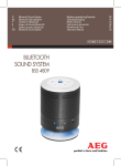
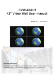
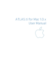
CVW-42AK2
Video Wall User manual
Model No.: CVW-42AK2
Operation Instructions
Thank you for purchasing this product. For optimal performance and safety, read
these instructions carefully. Please keep this manual for future reference.
Disclaimers
The information in this manual has been carefully checked and is believed to be accurate. Cypress
Technology assumes no responsibility for any infringements of patents or other rights of third parties
which may result from its use.
Cypress Technology assumes no responsibility for any inaccuracies that may be contained in this
document. Cypress also makes no commitment to update or to keep current the information contained in
this document.
Cypress Technology reserves the right to make improvements to this document and/or product at any
time and without notice.
Copyright Notice
No part of this document may be reproduced, transmitted, transcribed, stored in a retrieval system, or
any of its part translated into any language or computer file, in any form or by any means - electronic,
mechanical, magnetic, optical, chemical, manual, or otherwise - without express written permission and
consent from Cypress Technology.
© Copyright 2011 by Cypress Technology. All Rights Reserved.
Version 1.0 March 2011
Trademark Acknowledgments
All products or service names mentioned in this document may be trademarks of the companies with
which they are associated.
Revision History
2
Version No
Date
Summary of Change
VR0
VR1
VR2
20120821
Preliminary Release
20121012
Add RS-232 Commands
20121126 OSD Menu
WWW.CYPRESS.COM.TW
Table of Contents
1. Introduction..............................................................................5
2. Features..................................................................................5
3. Applications.............................................................................5
4. Specifications..........................................................................5
5. LCD TV Panel Installation.......................................................6
6. LCD Panel Rear Side..............................................................7
7. LCD Panel Rear Side Installation Instruction..........................8
8. System Operation....................................................................9
9. RS-232 Commands.................................................................9
10. Remote Control.....................................................................10
11. On-Screen Menu Display.......................................................11
Important Information Warning
CAUTION
RISK OF ELECTRIC SHOCK
DO NOT OPEN
CAUTION: TO REDUCE THE RISK OF ELECTRIC
SHOCK, DO NOT REMOVE SCREWS.
NO USER-SERVICEABLE PARTS
INSIDE.
REFER SERVICING TO QUALIFIED
SERVICE PERSONNEL.
The lightning flash and exclamation mark are intended to tell
which parts inside this product are at risk of electric shock.
Warning: To reduce the risk of fire or electric shock, do not expose this apparatus to rain or
moisture. Do not place liquid containers (flower vase, cups, cosmetics, etc.) above the set
(including on shelves above, etc.).
1. Power Supply
Only operate this product from the type of power supply included in the package. If you are
not sure what the voltage is in your home or office please consult your local power provider.
Disconnect the product before installation or maintenance.
2. Overloading
Do not overload a wall outlet, extension cord or adapter as this may result in fire or electric
shocks.
3. Liquids
This product should not be exposed to any liquid. Also, no containers filled with liquid should
be placed on the device.
4. Cleaning
Disconnect the product before cleaning. Please wipe the screen gently with a soft cloth.
Do not use chemical solvents to clean this product as this will damage the exterior casing,
tinted glass and the remote controller.
5. Mounting
Mount this product on a stable, even surface.
6. Cable
Do not intertwine, pull or compress the power cable, otherwise it can wear out and get
damaged. When this system is being installed do not place any cable beneath the product,
otherwise electric shocks or short circuits could occur.
4
WWW.CYPRESS.COM.TW
1. Introduction
The video wall is the best solution for advertise, entertainment and display the information
to the public. To attract audience’s attention is captured by the bright, moving, constantly
changing and relevant messages. Through RS-232 control, it allows users to control
different views from the video wall.
2. Features
●
●
●
●
Supports 2x2 / 3x3 / 4x4 / 5x5 video wall
Supports Full HD 1920 x 1080 LCD panel.
Through RS-232 control video wall.
Using one single remote control to select different combination to the display.
3. Applications
Video Wall systems can operate and apply for public places, Control rooms, Retail Sales
Environments, Schools, Hotels and more.
4. Specifications
Model. No
CVW-42AK2
SPECIFICATION
Screen Size (Inches)
Aspect Ratio
Contrast Ratio
Viewing Angle Range
Panel Resolution
Response Time (ms)
Brightness
VIDEO
42
16:9
3500:1
178°
1920 x 1080
8
700 cd/m2
HDMI Compatibility
SD: 480p, 576p,
HD: 720 p@50/60,1080i@50/60,1080p@50/60
VGA Compatibil i t y
VGA 640x480@60,72,75
SVGA 800x600@56,60,72,75
XGA 1024x768@60,70,75
SXGA 1280x1024@60
1920x1080@60
INPUT/OUTPUT
HDMI Interface
1 rear
RS-232
2 rear (1 male in use, 1 female in use)
15 Pin D-Sub
1 rear
IR Port
1 rear
GENERAL
Power Supply
100V~240V
Power Consumption (W)
180
On Screen Display Languages
Chinese, English
Dimension (H X V X D) mm
957.4 x 550.2 x 110.5
Package Dimension (H X V X D) mm
1080 x 690 x 220
Net Weight (Kg)
21
Gross Weight (Kg)
23
Accessory
Power Cord
1
Remote Control With Batteries For RS-232 Control
1/Video wall
And Video Wall
User Manual
Yes
Warranty Card
Yes
HDMI Splitter
Option
DCE to DTE RS-232 Cable
1
IR Extension Cable
1/Video wall
Mounting Kit
Option
Note: Panel vender different the specification will be different.
WWW.CYPRESS.COM.TW
5
5. LCD TV Panel Installation (For one unit only)
Panel Installation:
Use of this product with any accessory not included in the original package may cause serious problems which could result in injury.
Required accessories:
Product spec:
Make sure all the accessories are included in
the package.
Maximum weight: 90kg Net weight: 5kg
● Holding strip x 1
● 1/4 Expansion bolts x 4
● #12 Wood screw x 8
● M5 Assembly screw x 4
● Hanging Strip x 2
Installation:
⑴ Choosing the right wall
●
●
●
●
⑵ Hanging Strip Assembly :
Select a wall with a thickness of at least 5cm
The wall should be made of a strong material
If the system is being set up on a wood wall, please use the 8 x #12 wood screws (D)
If set up is to occur on a concrete wall,
please use 4 x 1/4 Expansion bolts. (C)
● When assembling the Hanging Strip make
sure the LCD panel is safely secured.
● During the installation make sure the
power plug is disconnected.
● Using 4 x M5 Assembly screws (E) Screw
the Hanging strip and LCD panel together.
(C)
(D)
⑶ Attaching the Hanging Strip:
● When attaching the Hanging Strip make sure
the LCD panel is safely secured.
● Attach the Hanging Strip to the Holding Strip
(Make sure the Holding Strip is properly
aligned with the Hanging Strip.)
⑷ Screw Hanging Strip :
● Make sure the Safety bolts are screwed in
correctly.
● The Safety bolts need to be screwed in
correctly to prevent the LCD panel from
dropping.
Note: The Safety bolts need to
be screwed in correctly.
6
WWW.CYPRESS.COM.TW
6. LCD Panel Rear Side
①
-
HDMI IN
⑥
⑦
+
②
③
④
MENU
RETURN
POWER
⑧
RS-232 OU
RS-232 IN
VGA IN
⑨
⑤
⑩
R IN
⑪
①-/+ Buttons: Press these buttons to scroll down/up in the Menu selection and value setting.
②MENU: Press this button to enter into the menu selection and press it again to confirm the selection.
③RETURN: Press this button to return from the selection and get back to the upper menu or exit OSD function.
④POWER: Press this button to switch on or set the device to standby mode.
⑤Power LED: This LED will illuminated in green when the device is switched on and red when in standby mode.
⑥AC IN & Power switch: Plug the power cord included in the package and connect it with AC wall outlet. Toggle the switch to turn on and off the
power.
⑦HDMI IN: Connect with input source equipment such as DVD/Blu-ray player for image display on the LCD panel/video wall.
⑧VGA IN: Connect with input srouce equipment such as PC/NB for image display on the LCD panel/wall.
⑨RS-232 IN: Connect from PC/NB with the RS-232 cable included in the package for RS-232 command sending and control over the LCD panel/
video wall. (See section 9 for detail commands)
⑩RS-232 OUT: Connect to the RS-232 IN of the next panel with the RS-
232 cable included in the package for video wall signal extending. (Detail connection please referes to next section)
⑪IR IN: Connect the IR extender on the first panel only for recieving the IR signal from the remote control of the device.
WWW.CYPRESS.COM.TW
7
7. LCD Pannel Rear Side Installation Instruction
1. Connect the source to the HDMI splitter (CHDMI-4M) input port and the HDMI splitter output ports connected to each Monitor’s HDMI input port (no need to follow the panel connection sequences).
2. The IR receiver cable need to connect to the first Monitor’s IR receiver port (from the rear side, the right top side is the first Monitor). If the user connected to the wrong Monitor, the
IR will work abnormal.
3. For 2 by 2 Video Wall, the package will included 3 sets of RS-232 control cable (DCE to
DTE RS-232 control cable), the cables connection sequence as below:
First RS-232 cable: Connect the DCE of RS-232 to first set of Monitor’s RS-232 output port (DTE connector), and connect the DTE of RS-232 to the second set of Monitor’s
RS-232 input port (DCE connector).
Second RS-232 cable: Connect the DCE of RS-232 to second set of Monitor’s RS-232 output port (DTE connector), and connect the DTE of RS-232 to the third set of Monitor’s RS-232 input port (DCE connector).
Third RS-232 cable: Connect the DCE of RS-232 to third set of Monitor’s RS-232 output port (DTE connector), and connect the DTE of RS-232 to the forth set of Monitor’s
RS-232 input port (DCE connector).
Note: 3 by 3, 4 by 4 and 5 by 5 vice versa.
2 by 2 Video Wall installation:
FULL
①
②
④
③
SINGLE
PS3
2
CHDMI-4M
(HDMI Splitter)
①
②
④
③
1
HDMI
IR Cable
HDMI
3
HDMI
HDMI
4
8
WWW.CYPRESS.COM.TW
Different combination will have different sets of accessory
Video wall Accessory
Monitor
Power Cord
RS-232 cable (DCE to DTE)
IR cable
Remote Control
CHDMI-4M
CHDMI-210T
CLUX-16E
2x2
4
4
3
1
1
1
x
x
3x3
9
9
8
1
1
x
1
x
4x4
16
16
15
1
1
x
x
1
5x5
25
25
24
1
1
x
x
2
8. System Operation
After the system installation is completed, the user can select the desired display
combinations with the remote control. For additional information on how to use the remote
control please refer to section 9.
9. RS-232 Commands
CVW-42AK2
PIN
1
2
3
4
5
6
7
8
9
RS-232 Protocol:
Baud Rate: 19200bps
Data bit: 8 bits
Parity: None
Stop Bit: 1 bit
Flow Control: None
Assignment
NC
TxD
RxD
NC
GND
NC
NC
NC
NC
COMMAND
0x23 0x53 0x30 0x30 0x31 0x23
0x23 0x53 0x30 0x30 0x30 0x23
0x23 0x43 0x30 0x30 0x31 0x23
0x23 0x43 0x30 0x30 0x30 0x23
0xEF 0x06 0xD2 0xC0 0x20 0x00 0x04 0xEE
0xEF 0x06 0xD3 0xC0 0x20 0x01 0x04 0xEE
0xEF 0x06 0xD7 0xC0 0x20 0x01 0x08 0xEE
0xEF 0x06 0xD8 0xC0 0x20 0x01 0x09 0xEE
0xEF 0x06 0xE0 0xC0 0x20 0x01 0x11 0xEE
0xEF 0x06 0xDF 0xC0 0x20 0x01 0x10 0xEE
0xEF 0x06 0xDF 0xC0 0x20 0x01 0x19 0xEE
0xEF 0x05 0xD7 0xC0 0x22 0x07 0xEE
0xEF 0x05 0xD0 0xC0 0x22 0x00 0xEE
WWW.CYPRESS.COM.TW
PC Control Interface
PIN
1
2
3
4
5
6
7
8
9
Assignment
NC
RxD
TxD
NC
GND
NC
NC
NC
NC
ACTION
POWER ON
POWER OFF
UNDER SCAN
OVER SCAN
SINGLE
2x2
3x2
3x3
4x3
4x4
5x5
HDMI
VGA
9
10. Remote Control
①
②
③
④
⑤
⑥
⑦
⑧
⑨
⑩
⑪
① POWER: Turn the system on.
② POWER OFF: Turn the system off.
③ SINGLE: This option allows one input source to be shown on all displays identically.
④ FULL: This option allows one input source to be enlarge four times bigger and display on a 2x2 video wall.
Note: 3x3 and 4x4 video walls have additional combinations.
⑤ ▲ / ▼ / ◄ / ►: After entering the menu press up/down/left/right to setup each LCD panel.
⑥ OK: Enter into factory mode.
⑦ RETURN: Press to go back to the previous setting.
⑧ MENU: Press to enter each LCD TV menu.
⑨ HDMI:Press to switch to HDMI input.
⑩ VGA: Press to switch to VGA input.
⑪ U/OVER: When the display under full screen, press to over or under scan the picture.
10
Note: Item n 3,4 and 11, only work when HDMI input.
WWW.CYPRESS.COM.TW
11. On-Screen Menu Display
Certain menu items cannot be changed. Adjusting the menu settings depends on the signal, input source
and the specific menu setting.
Press
to display the menu screen
For Menu Screen only
For HDMI only
For PC only
WWW.CYPRESS.COM.TW
11
MPM-CVW42AK2