1
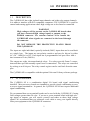
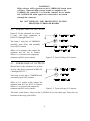
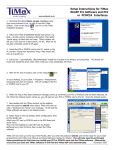
Digital I/O
CYPDISO 8P
PCI-Bus 8-Channel
Isolated Interface Board
USER’S MANUAL
VER. 6
• APRIL 2002
&
No part of this manual may be reproduced without permission.
CyberResearch®, Inc.
www.cyberresearch.com
25 Business Park Dr., Branford, CT 06405 USA
203-483-8815 (9am to 5pm EST) FAX: 203-483-9024
©Copyright 2002
All Rights Reserved.
April, 2002
The information in this document is subject to change without prior notice in order
to improve reliability, design, and function and does not represent a commitment
on the part of CyberResearch, Inc.
In no event will CyberResearch, Inc. be liable for direct, indirect, special,
incidental, or consequential damages arising out of the use of or inability to use
the product or documentation, even if advised of the possibility of such damages.
This document contains proprietary information protected by copyright. All rights
are reserved. No part of this manual may be reproduced by any mechanical,
electronic, or other means in any form without prior written permission of
CyberResearch, Inc.
TRADEMARKS
“CyberResearch,” and “CyPDISO 8P” are trademarks of CyberResearch, Inc.
Other product names mentioned herein are used for identification purposes only
& may be trademarks and/or registered trademarks of their respective companies.
• NOTICE •
CyberResearch, Inc. does not authorize any CyberResearch product for use in life
support systems, medical equipment, and/or medical devices without the written
approval of the President of CyberResearch, Inc. Life support devices and
systems are devices or systems which are intended for surgical implantation into
the body, or to support or sustain life and whose failure to perform can be
reasonably expected to result in injury. Other medical equipment includes devices
used for monitoring, data acquisition, modification, or notification purposes in
relation to life support, life sustaining, or vital statistic recording. CyberResearch
products are not designed with the components required, are not subject to
the testing required, and are not submitted to the certification required to ensure
a level of reliability appropriate for the treatment and diagnosis of humans.
i
ii
Table of Contents
1.0 INTRODUCTION . . . . . . . . . . . . . . . . . . . . . . . . . . . . . . . . . . . 1
1.1 DESCRIPTION . . . . . . . . . . . . . . . . . . . . . . . . . . . . . . . . . . . . . 1
1.2 ACCESSORIES . . . . . . . . . . . . . . . . . . . . . . . . . . . . . . . . . . . . 1
2.0 SOFTWARE INSTALLATION . . . . . . . . . . . . . . . . . . . . . . . . 3
3.0 HARDWARE INSTALLATION . . . . . . . . . . . . . . . . . . . . . . . 5
3.1 INSTALL THE HARDWARE . . . . . . . . . . . . . . . . . . . . . . . . . . . 5
3.2 AC INPUT FILTER . . . . . . . . . . . . . . . . . . . . . . . . . . . . . . . . . . 5
4.0 INTERFACING . . . . . . . . . . . . . . . . . . . . . . . . . . . . . . . . . . . . . 7
4.1 CONNECTOR DIAGRAM . . . . . . . . . . . . . . . . . . . . . . . . . . . . 7
4.2 FORM C RELAY OUTPUTS . . . . . . . . . . . . . . . . . . . . . . . . . . . 8
4.3 FORM A RELAY OUTPUTS. . . . . . . . . . . . . . . . . . . . . . . . . . . . 8
4.4 ISOLATED INPUTS . . . . . . . . . . . . . . . . . . . . . . . . . . . . . . . . . . 9
4.5 EXTENDING THE INPUT RANGE . . . . . . . . . . . . . . . . . . . . . 9
5.0 SPECIFICATIONS. . . . . . . . . . . . . . . . . . . . . . . . . . . . . . . . . . . . . . 11
This page deliberately left blank.
iv
1.0 INTRODUCTION
1.1
DESCRIPTION
The CyPDISO 8P has eight isolated input channels and eight relay-output channels.
It is made to interface with PCI-compatible computers. The CyPDISO 8P is used for
control and sensing applications where high voltage are to be sensed or controlled.
WARNING!
High voltages will be present on the CyPDISO 8P board when
you have connected high voltage inputs or outputs to the
PDISO8 connector. Use extreme caution! Never handle the
CyPDISO 8P when signals are connected to the board through
the connector.
DO NOT REMOVE THE PROTECTIVE PLATES FROM
THE CyPDISO 8P.
The inputs are eight individual, optically-isolated (500V) inputs that can be read back
as a single byte. The inputs are not polarity sensitive and may be driven by either
AC (50 - 1000 Hz) or DC. Each input has a programmable low-pass filter with a
time constant of 5 ms (200 Hz).
The outputs are eight, electromechanical relays. Five relays provide Form-C connections and three provide normally-open Form-A connections. The relays are controlled
by writing to an 8-bit port. The relay control register can be read back from the same
port.
The CyPDISO 8P is compatible with the optional Universal Library software package.
1.2
ACCESSORIES
The CyPDISO 8P is a combination digital I/O board with signal conditioning
installed. Most accessory boards are intended to provide signal conditioning or easy
to access signal termination. In general, the CyPDISO 8P will not require additional
signal conditioning.
We recommend that screw terminal boards not be used with the CyPDISO 8P if using
field voltages greater than 24 volts. If you use a screw terminal board with high voltage inputs or outputs, you will expose yourself and others to those high voltage
signals. We recommend that you construct a safe cable to carry your signals directly
from your equipment to the CyPDISO 8P connector.
1
This page deliberately left blank.
2
2.0 SOFTWARE INSTALLATION
Before installing the CyPDISO 8P, first install the InstaCal™ installation, calibration
and test utility included with your board. You can install InstaCal from either the
InstaCal disk set or from the optional Universal Library™, if ordered.
InstaCal creates a configuration file that your application software (and the Universal
Library) referes to. so your software automatically accesses the exact configuration
of the board. For information on the installation and operation of InstaCal, refer to
the Software Installation Manual.
3
This page deliberately left blank.
4
3.0 HARDWARE INSTALLATION
The CyPDISO 8P is completely plug-and-play. There are no manually configured
options. Simply install the board and run InstaCal to verify proper installation.
3.1
INSTALLING THE HARDWARE
1. Power OFF your computer and remove the cover.
2. Insert the CyPDISO 8P securely into any available PCI slot. Make sure the board
is properly seated in the slot or damage to your PC or board could result.
3. Replace the cover and power ON your computer.
4. Run InstaCal to configure your board and test the installation
3.2
AC INPUT FILTER
The inputs are eight individual, optically isolated (500V) inputs that may be read back
as a single byte. The inputs are not polarity sensitive and may be driven by either AC
(50-1000 Hz) or DC. Each input has a software enabled/disabled low-pass filter
with a time constant of 5 ms (200 Hz).
The input filters are described and set by InstaCal. The filter must be used for AC
inputs and should be used for almost all DC inputs. Unless you have reason to turn
off a filter, you should enabled it.
5
This page deliberately left blank.
6
4.0 INTERFACING
This short introduction to the electronics most often needed by digital I/O board users
covers the following:
y
y
y
y
y
y
4.1
Connector diagram.
FORM C relay outputs.
FORM A relay outputs.
Isolated inputs.
Adding a resistor to expand the range of the isolated inputs.
Voltage dividers.
CONNECTOR DIAGRAM
The CyPDISO 8P use a single 37-pin connector.
INPUT 7B
INPUT 6B
INPUT 5B
INPUT 4B
INPUT 3B
INPUT 2B
INPUT 1B
INPUT 0B
RELAY 7(NO)
RELAY 6(NO)
RELAY 5(NO)
RELAY 4 (C)
RELAY 3(NC)
RELAY 3 (NO)
RELAY 2 (C)
RELAY 1 (NC)
RELAY 1 (NO
RELAY 0 (C)
1
2
3
4
5
6
7
8
9
10
11
12
13
14
15
16
17
18
19
20
21
22
23
24
25
26
27
28
29
30
31
32
33
34
35
36
37
INPUT 7A
INPUT 6A
INPUT 5A
INPUT 4A
INPUT 3A
INPUT 2A
INPUT 1A
INPUT 0A
RELAY 7(C)
RELAY 6(C)
RELAY 5(C)
RELAY 4 (NC)
RELAY 4 (NO)
RELAY 3 (C)
RELAY 2 (NC)
RELAY 2 (NO)
RELAY 1 (C)
RELAY 0 (NC)
RELAY 0 (NO)
Figure 5-1. 37-Pin Board Connector
7
WARNING!
High voltages will be present on the CyPDISO 8P board when
you have connected high voltage inputs or outputs to the
CyPDISO 8P connector. Use extreme caution! Never handle
the CyPDISO 8P when signals are connected to the board
through the connector.
DO NOT REMOVE THE PROTECTIVE PLATES
FROM THE CYPDISO 8P BOARD.
4.2
FORM C RELAY OUTPUTS
Figure 5-2 is the schematic for a form
C relay, like those connected at
RELAY 0 through RELAY 4.
The form C relay has a COMMON,
normally open (NO) and normally
closed (NC) contact.
When a 0 is written to the output, the
common and NC are in contact.
When a 1 is written to the output the
common and NO are in contact.
4.3
Figure 5-2. Form C Relay (0) Contacts
FORM A RELAY OUTPUTS
Shown here is the schematic for a form
A relay, like those connected at RELAY
5 through RELAY 7.
The form A relay has a COMMON and
a normally open (NO) contact.
When a 0 is written to the output, the
common and NO are NOT in contact.
When a 1 is written to the output the
common and NO are in contact.
Figure 5-3. Form A Relay (5) Contacts
The form A and form C relays on the CyPDISO 8P are the same type. Only the connections to the relay poles differ.
8
4.4
ISOLATED INPUTS
The CyPDISO 8P board has are eight isolated input channels. The schematic of a single
channel is shown in Figure 4-4.
The signals are routed through a bridge rectifier so that the inputs are not polarity
sensitive.
1 .6 K
Figure 5-4. Isolated Input Schematic- Simplified
4.5
EXTENDING THE INPUT RANGE
To extend the input range beyond the 5-28V specified, add an external resistor.
Figure 4-5 shows the resistor and the equations used to calculate resistor values
for a given Vin.
1.6 K
V in
8
Figure 5-5. Input Range-Extending Resistor
9
This page deliberately left blank.
10
5.0 SPECIFICATIONS
Power Consumption
+5V
All Relays Off
All Relays On
0.4A typical
1.0A typical
Relay Specifications
Number
Contact Configuration
Contact Rating
Contact Type
Contact Resistance
8
5 form C, relay 0 to relay 4
3 form A, relay 5 to relay 7
6A @ 120VAC or 28VDC resistive
Gold-overlayed silver
100 milliohms max.
Operate Time
Release Time
Vibration
Shock
Dielectric Isolation
Life Expectancy
20 milliseconds
10 milliseconds max.
10 to 55 Hz (Dual amplitude 1.5mm)
10G (11 milliseconds)
500V (1 minute)
10 milliohm mechanical operations, min.
Isolated Inputs
Number
Voltage Range
DC
AC
Isolation
Resistance
Response
w/o Filter
w/ Filter
Filters
Time Constant
Filter Control
Power-Up /Reset
8
5 to 28V (Not TTL compatible)
5 to 28V (50 to 1000 Hz)
500V
1.6k Ohms min
20 µs
5 ms
5 ms (200 Hz)
Each input individually programmable
Filters off
Environmental
Operating Temperature Range
Storage Temperature Range
Humidity
0 to 70°C
−40 to 100°C
0 to 90%, non-condensing
11
This page deliberately left blank.
12
This page deliberately left blank.
14
Product Service
Diagnosis and Debug
CyberResearch, Inc. maintains technical support lines staffed by experienced Applications
Engineers and Technicians. There is no charge to call and we will return your call promptly
if it is received while our lines are busy. Most problems encountered with data acquisition
products can be solved over the phone. Signal connections and programming are the two
most common sources of difficulty. CyberResearch support personnel can help you solve
these problems, especially if you are prepared for the call.
To ensure your call’s overall success and expediency:
1) Have the phone close to the PC so you can conveniently and quickly take action
that the Applications Engineer might suggest.
2) Be prepared to open your PC, remove boards, report back-switch or jumper
settings, and possibly change settings before reinstalling the modules.
3) Have a volt meter handy to take measurements of the signals you are trying to
measure as well as the signals on the board, module, or power supply.
4) Isolate problem areas that are not working as you expected.
5) Have the source code to the program you are having trouble with available so
that preceding and prerequisite modes can be referenced and discussed.
6) Have the manual at hand. Also have the product’s utility disks and any other
relevant disks nearby so programs and version numbers can be checked.
Preparation will facilitate the diagnosis procedure, save you time, and avoid repeated calls.
Here are a few preliminary actions you can take before you call which may solve some of
the more common problems:
1) Check the PC-bus power and any power supply signals.
2) Check the voltage level of the signal between SIGNAL HIGH and SIGNAL LOW,
or SIGNAL+ and SIGNAL– . It CANNOT exceed the full scale range of the board.
3) Check the other boards in your PC or modules on the network for address and interrupt
conflicts.
4) Refer to the example programs as a baseline for comparing code.
15
Warranty Notice
CyberResearch, Inc. warrants that this equipment as furnished will be free from defects in
material and workmanship for a period of one year from the confirmed date of purchase by
the original buyer and that upon written notice of any such defect, CyberResearch, Inc. will,
at its option, repair or replace the defective item under the terms of this warranty, subject to
the provisions and specific exclusions listed herein.
This warranty shall not apply to equipment that has been previously repaired or altered outside our plant in any way which may, in the judgment of the manufacturer, affect its
reliability. Nor will it apply if the equipment has been used in a manner exceeding or
inconsistent with its specifications or if the serial number has been removed.
CyberResearch, Inc. does not assume any liability for consequential damages as a result
from our products uses, and in any event our liability shall not exceed the original selling
price of the equipment.
The equipment warranty shall constitute the sole and exclusive remedy of any Buyer of
Seller equipment and the sole and exclusive liability of the Seller, its successors or assigns,
in connection with equipment purchased and in lieu of all other warranties expressed implied
or statutory, including, but not limited to, any implied warranty of merchant ability or fitness
and all other obligations or liabilities of seller, its successors or assigns.
The equipment must be returned postage prepaid. Package it securely and insure it. You will
be charged for parts and labor if the warranty period has expired.
Returns and RMAs
If a CyberResearch product has been diagnosed as being non-functional, is visibly damaged,
or must be returned for any other reason, please call for an assigned RMA number. The
RMA number is a key piece of information that lets us track and process returned merchandise with the fastest possible turnaround time.
PLEASE CALL FOR AN RMA NUMBER!
Packages returned without an RMA number will be refused!
In most cases, a returned package will be refused at the receiving dock if its contents are
not known. The RMA number allows us to reference the history of returned products and
determine if they are meeting your application’s requirements. When you call customer
service for your RMA number, you will be asked to provide information about the product
you are returning, your address, and
a contact person at your organization.
Please make sure that the RMA number is
prominently displayed on the outside of the box.
• Thank You •
16